ARB compressor/ AOB switch install

The ARB compressors are geared to multipurpose application, ie, lockers AND using air for tires/tools. For locker operation, the switches are going to be in the cabin, and consequently, if you also want air for tires.

We should have added that this is exactly the reason behind our questions/desire for clarification. We will be running a total of three switches: 1 to control the compressor plus two more for the front and rear lockers.

If I was only using it for air, I probably would have just wired a switch under the hood as well (or just done CO2).

Has anyone else on this forum wired up a complete ARB/AOB/Locker setup?
 
We should have added that this is exactly the reason behind our questions/desire for clarification. We will be running a total of three switches: 1 to control the compressor plus two more for the front and rear lockers.

If I was only using it for air, I probably would have just wired a switch under the hood as well (or just done CO2).

Has anyone else on this forum wired up a complete ARB/AOB/Locker setup?

Yes, I have and I'm in Colorado...Denver. PM me if you run into any issues...your diagram looks right. I did not install a reservoir or additional switches for air lockers...yet. I've just taped off that part of the ARB loom under the hood.
 
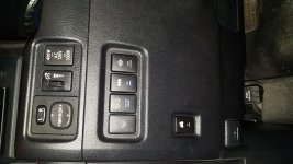
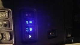
All done...

Just finished this install tonight. Wired the three AOB switches to the ARB harness as identified above. Tapped into the washer heater switch for switched ignition (blue wire) and illumination with headlights (green wire). With this configuration, 1) the key must be turned on in order to activate the switches and 2) the buttons illuminate with the headlights but do not dim (from my understanding that would have required me to splice into the gray wire). Will probably leave things as they are for awhile and then decide if I really need the dimming feature.

Thanks for the good info in this thread and for the offers of assistance. I have never done this sort of electrical work on a car before, but I had enough help both in person and from the web that the install was accomplished with no major delays or issues. The one thing I would reiterate is double check the AOB wiring diagram and provided harness since ours definitely differed from the OPs in the pin order/wire colors. Not really a problem, but just something to be aware of.
 
GChristo;Any update on your install? Did you use the " isolation " harness on the ARB to wire or did you go another route? What did you do with the thin black ARB wire bundled with the +'ve and -'ve you connect to the battery?
 
I am hoping to tackle my CKMA12 install with the AOB switch tomorrow. I dont have any plans to use this compressor for lockers anytime in the forseable future. Can I just tape up the solenoid cables and tuck them out of the way? Or is it going to be a problem ONLY wiring up the isolation switch?

Thanks for doing these write ups!
 
I am hoping to tackle my CKMA12 install with the AOB switch tomorrow. I dont have any plans to use this compressor for lockers anytime in the forseable future. Can I just tape up the solenoid cables and tuck them out of the way? Or is it going to be a problem ONLY wiring up the isolation switch?


Thanks for doing these write ups!


I just taped mine up and tucked them away no problem. Compressor works great!


Sent from my iPhone using Tapatalk
 
I am hoping to tackle my CKMA12 install with the AOB switch tomorrow. I dont have any plans to use this compressor for lockers anytime in the forseable future. Can I just tape up the solenoid cables and tuck them out of the way? Or is it going to be a problem ONLY wiring up the isolation switch?

Thanks for doing these write ups!

Yep, exactly what I did, it'll work just fine!
 
For those of you that are having questions on what goes where... be sure to read the two pages that -follow- that wiring diagram posted above. It explains the complete ordeal and has a couple of warnings you must heed.

1. Don't cut the diodes out of the wire if you shorten it.
2. Switch 1 MUST be the REAR LOCKER
3. +12 needs at least an 8 amp fuse in the circuit.
 
I have read just about every post I can find on installing ARB CKMA12 compressor using the ARB harness and an AOB switch. This is my first electrical mod so I have a couple of questions. Here is my layout:

2015 4R Trail Premium
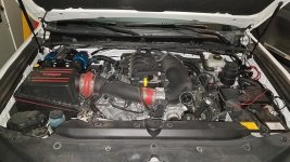
ARB compressor on Slee bracket under hood.
Using ARB harness per instructions.
AOB switch mounted in isolation loom.
Not using air locker switches in 1 or 2 on ARB loom.
Passed ARB loom post the plug-in fitting through firewall below dash.
Using AOB compressor switch instead on one supplied with ARB compressor.

ARB loom to AOB switch per CJACOb13's post above:
Black (both) to black
blue/white to blue/yellow
red to red/yellow
red/yellow to green/yellow

ARB Loom:
blue/white to Green on wiper de-icer switch
red/yellow to 12V supply but where?

After reading the "switch or not to switch" post and the possibility of frying the ECU / Instrument Cluster, wanted to ask for confirmation and answers to the following before I go live with this install:

There are two black wires going to posts (7&8) on back of the ARB switch. I assume you tie both of these black wires from the ARB into the black wire on the AOB switch?

Planning to use the green wire off the wiper de-icer switch to the blue/white wire on the ARB loom. I believe this will illuminate the AOB switch when the parking lights / headlights are on. Will this also dim the AOB switch? Or do I need to tie into the grey wire? That grey wire scares me because of concerns sending power back to ECU after reading the other post.

What is the best 12V source to connect the red/yellow wire (trigger) on the ARB loom in the cab to the ignition that works only when the key is turned to accessory or with engine running? Since I'm planning to splice into the de-icer switch, which wire would be appropriate for the ARB red/yellow? The blue one? See others that appear to tap into the fuse box. Is one source really better than the other?

I used the wiring diagrams and my multimeter to analyze the de-icer switch and came up with the scenario above. Still would like a vote of confidence being less experienced with electrical mods. Any help is much appreciated.
 
I have read just about every post I can find on installing ARB CKMA12 compressor using the ARB harness and an AOB switch. This is my first electrical mod so I have a couple of questions. Here is my layout:

2015 4R Trail Premium
ARB compressor on Slee bracket under hood.
Using ARB harness per instructions.
AOB switch mounted in isolation loom.
Not using air locker switches in 1 or 2 on ARB loom.
Passed ARB loom post the plug-in fitting through firewall below dash.
Using AOB compressor switch instead on one supplied with ARB compressor.

ARB loom to AOB switch per CJACOb13's post above:
Black (both) to black
blue/white to blue/yellow
red to red/yellow
red/yellow to green/yellow

ARB Loom:
blue/white to Green on wiper de-icer switch
red/yellow to 12V supply but where?

After reading the "switch or not to switch" post and the possibility of frying the ECU / Instrument Cluster, wanted to ask for confirmation and answers to the following before I go live with this install:

There are two black wires going to posts (7&8) on back of the ARB switch. I assume you tie both of these black wires from the ARB into the black wire on the AOB switch?

Planning to use the green wire off the wiper de-icer switch to the blue/white wire on the ARB loom. I believe this will illuminate the AOB switch when the parking lights / headlights are on. Will this also dim the AOB switch? Or do I need to tie into the grey wire? That grey wire scares me because of concerns sending power back to ECU after reading the other post.

What is the best 12V source to connect the red/yellow wire (trigger) on the ARB loom in the cab to the ignition that works only when the key is turned to accessory or with engine running? Since I'm planning to splice into the de-icer switch, which wire would be appropriate for the ARB red/yellow? The blue one? See others that appear to tap into the fuse box. Is one source really better than the other?

I used the wiring diagrams and my multimeter to analyze the de-icer switch and came up with the scenario above. Still would like a vote of confidence being less experienced with electrical mods. Any help is much appreciated.

I would like to know as well.
 
only when the key is turned to accessory or with engine running?

Cig Lighter or Seat Heater.

Both are easy to access.


ETA: Green wire... No, I do not believe that will "dim". Yes, the gray wire will "dim".
 
Last edited:
Cig Lighter or Seat Heater.

Both are easy to access.


ETA: Green wire... No, I do not believe that will "dim". Yes, the gray wire will "dim".

Yep, I found the Cig Lighter wire to be easiest. I just traced it back underneath the steering column and tapped into it.
 
So arb red/yellow tap into cig lighter and the blue white tap into gray wire from another switch?

Yes to the red/yellow tapped into cig lighter power.

I did not bother with a lighted/dimmer switch wire...my switch only lights when compressor powers on.
 
Here's some photos of the Bandi mount. I picked this one last week. Solid mounting solution for the ARB compressor. He has a few different options as well.

6cde86aeb1ffc37aac807bb164fa6e09.jpg
da07f1fffe3c04f34044714e8d8a4c15.jpg
8642e174bab348228b5c9c381d3257e0.jpg


Sent from my SAMSUNG-SM-G935A using Tapatalk

Hi,
Is that mounted on top of the relocation kit when the second battery is fitted to the front passenger side?
 
Does the AOB switch need to have an inline fuse added?
just did mine Sunday... the switch does not need a fuse, what it connects into needs a fuse. the 40 amp inline for the compressor will work, since the switch really only operates the relay
 
Folks...finished my wiring for my ARB twin compressor. I connected my blue and red/yellow wires to the add a tap for my other switches. The AOB compressor button doesn't light up with the other buttons when I have my lights on. I think I have to move the red/yellow wire to my ignition fuse with an add a tap to separate the two wires. The compressor works when I hit the button so everything is in working order. Any advice?
 

Attachments

  • 20191115_181543.jpg
    20191115_181543.jpg
    136.7 KB · Views: 1,454
  • 20191115_181611.jpg
    20191115_181611.jpg
    136.9 KB · Views: 1,324
  • 20191108_174204.jpg
    20191108_174204.jpg
    135.5 KB · Views: 1,235
  • 20191108_174218.jpg
    20191108_174218.jpg
    135.8 KB · Views: 1,247
  • 20191108_174152.jpg
    20191108_174152.jpg
    136.9 KB · Views: 1,254
  • 20191115_182800.jpg
    20191115_182800.jpg
    145.2 KB · Views: 1,258
We're working on a similar install this week as well. We're hoping you guys could take a look at how we believe we're supposed to make the connections and let us know if we've got it right or not??? The instructions and wire colors seemed to have changed some from previous threads we've checked out.

AOB instructions
View attachment 253195

These are the plugs we got with the switches.
View attachment 253197

ARB instructions
View attachment 253196

So just in case the hand-writing isn't showing up well enough I've typed it out here:


Isolation Switch:
ARB ---> AOB
Red/Yel -- > Red
Red ---> Green
Blu/wht --> Blue
Black ---> Black

Switch 1 (R):
ARB ---> AOB
Red ----> Red
Yel -----> Grn
Blu/wht ---> Blue
Black ----> Black

Switch 2 (F):
ARB ---> AOB
Yel ---> Red
Dk Grn ---> Green
Blu/Wht ---> Blue
Black ---> Black


Does this make sense/look right????

Thanks!!!

Can confirm this wiring diagram does work for Compressor and Rear Locker on Switch 1.
 

Members online

Forum statistics

Threads
278,309
Messages
3,554,068
Members
248,016
Latest member
Advally Service

Trending content

Back
Top