Body Mount Chop

FactoryRide

New member
Body Mount Chop

My reasons for doing this were to not have to shell out money for UCAs right now. They will happen eventually, but not right now while I’m using spacers as my lift solution. I am currently running 285 Hankook MTs with spidertrax wheel spacers and I believe that was my reason for the body mount rubbing. I had my alignment done right after I got the new tires and it helped a little bit, but I just wasn’t able to get enough positive castor to remedy the rubbing.
My solution was to chop my body mounts. I didn’t want them completely gone though. I feel like the function of them are to prevent the wheels from getting pushed back into the cab in a head on collision, so I wanted them to be somewhat present when I was finished.
I sat there and stared at them for about an hour trying to decide how I wanted to approach doing this, and here is what I came up with.
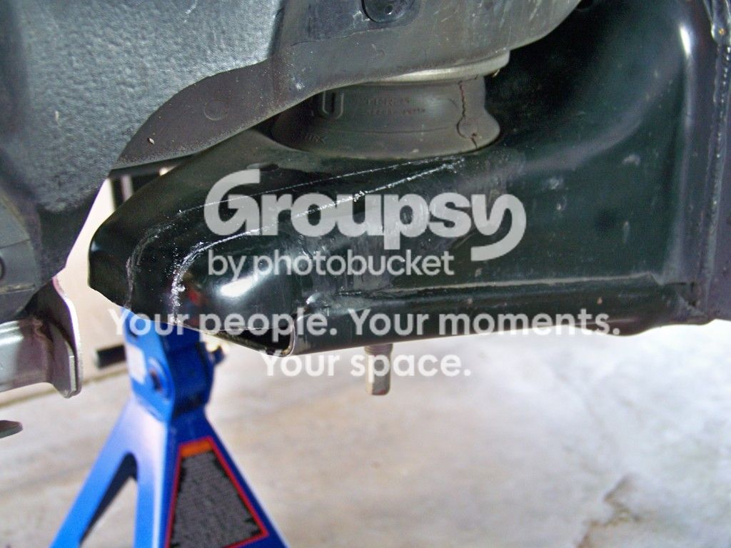
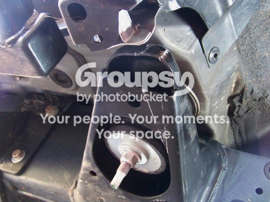
106_0911_zps2ac66203.jpg~original

106_0912_zpsb566262b.jpg~original

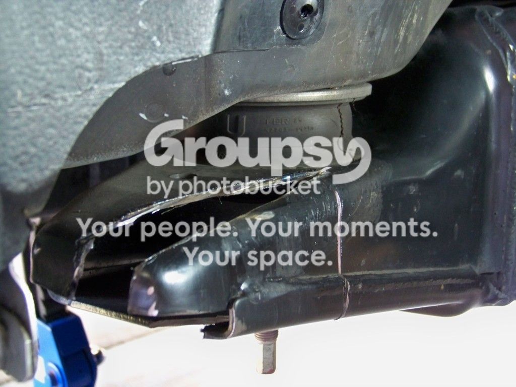
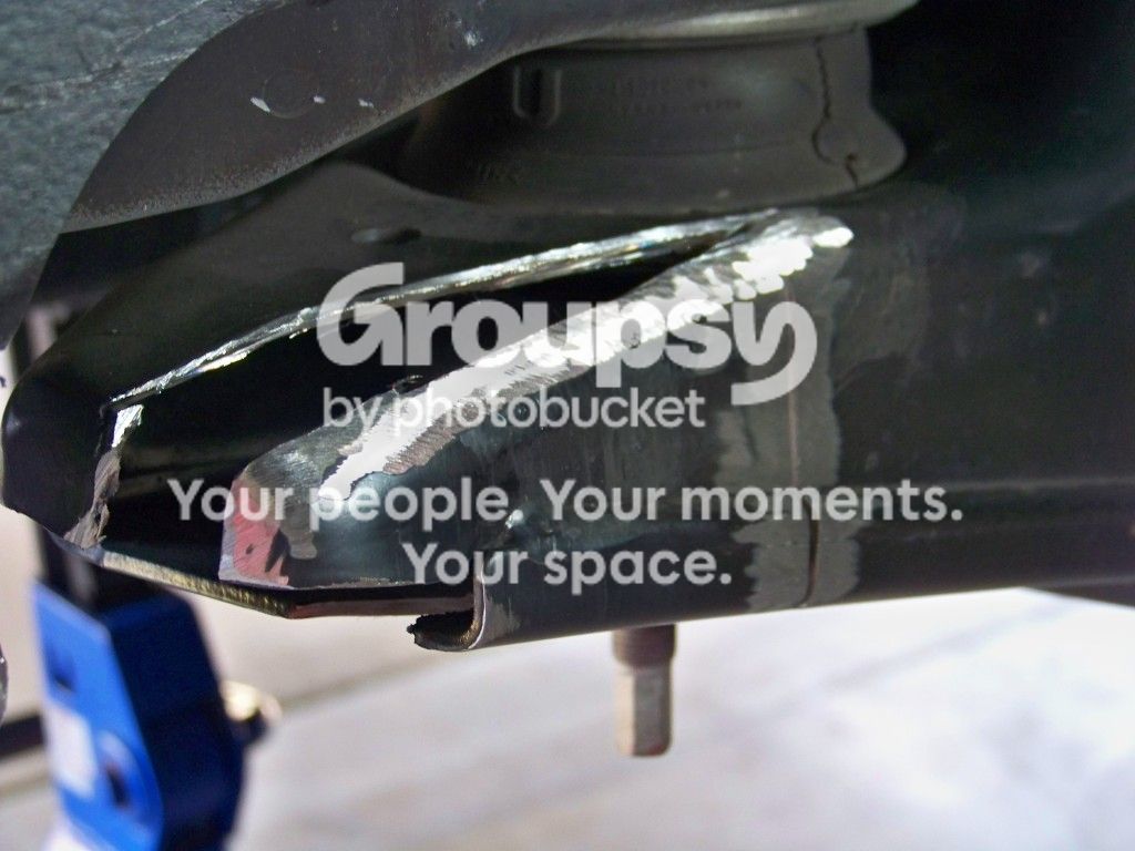
My plan was to cut out a ¾” wedge and push back and weld. I rented a sawzall thinking that would work, but the grinder with a cutting wheel turned out to work best.
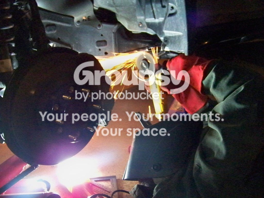
106_0910_zps7bbd51e2.jpg~original

Here it is after I got it cut out.
106_0913_zps48fc96bc.jpg~original

106_0915_zpsde789e79.jpg~original

Cleaned up to weld
106_0916_zpsffdfd61b.jpg~original

106_0917_zps93f0fda7.jpg~original

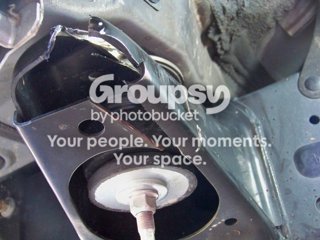
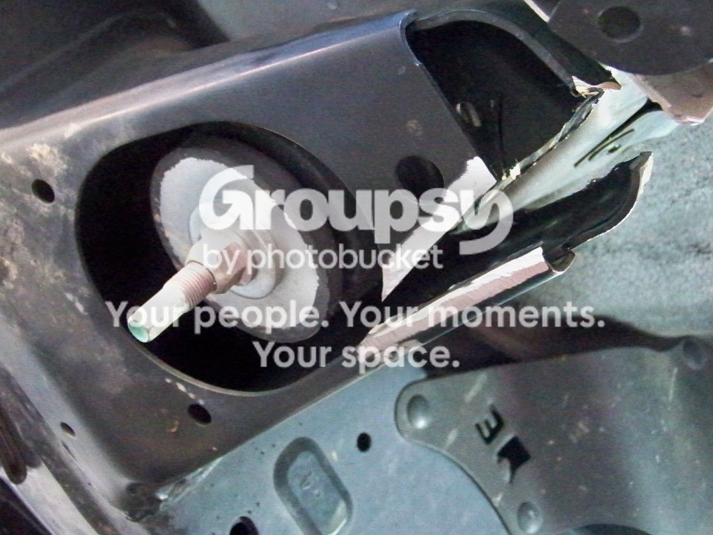
I then took the sledge hammer to it only to find that I was just getting bounce back and the piece wasn’t budging. So I thought some more. On the bottom side of the mount, it has the overlap that was causing my problems. I figured I’d cut into that and make a score mark to allow for it to move.
106_0916_zpsffdfd61b1_zpscd3e9e93.jpg~original

This fixed my problems, and I was able to line up the pieces to be able to weld.
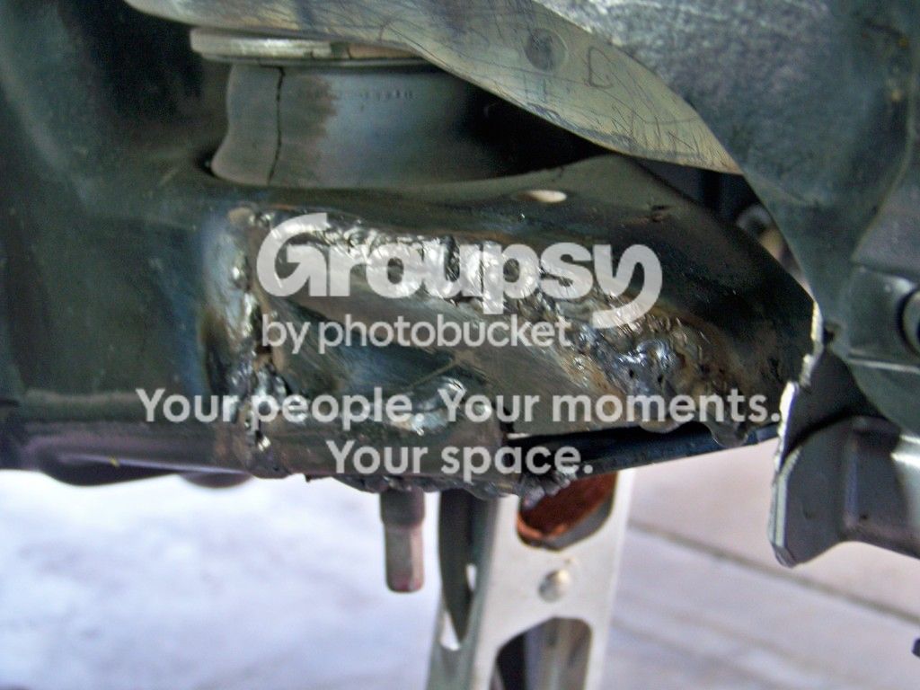
Now before I post pictures of my welds. Keep in mind I only started welding last semester and don’t have near enough time to be able to practice to be good with stick welding(shoulda got a Mig instead of a stick welder). My welds are functional and not pleasing to the eye lol. There were also places where I had to fill 1/4” to 1/2” gaps.
I welded the bottom together first.

106_0929_zps6fada4bc.jpg~original

106_0932_zps67274100.jpg~original

Then I broke out my pry bar to put in between the body and the frame to try and close the large gaps I had to tack the top part of the cut out together.
Once tacked, I started to weld it together. I did the passenger side first and it turned out as ugly as I had expected it to.
Passenger side after cleaned up a little bit.
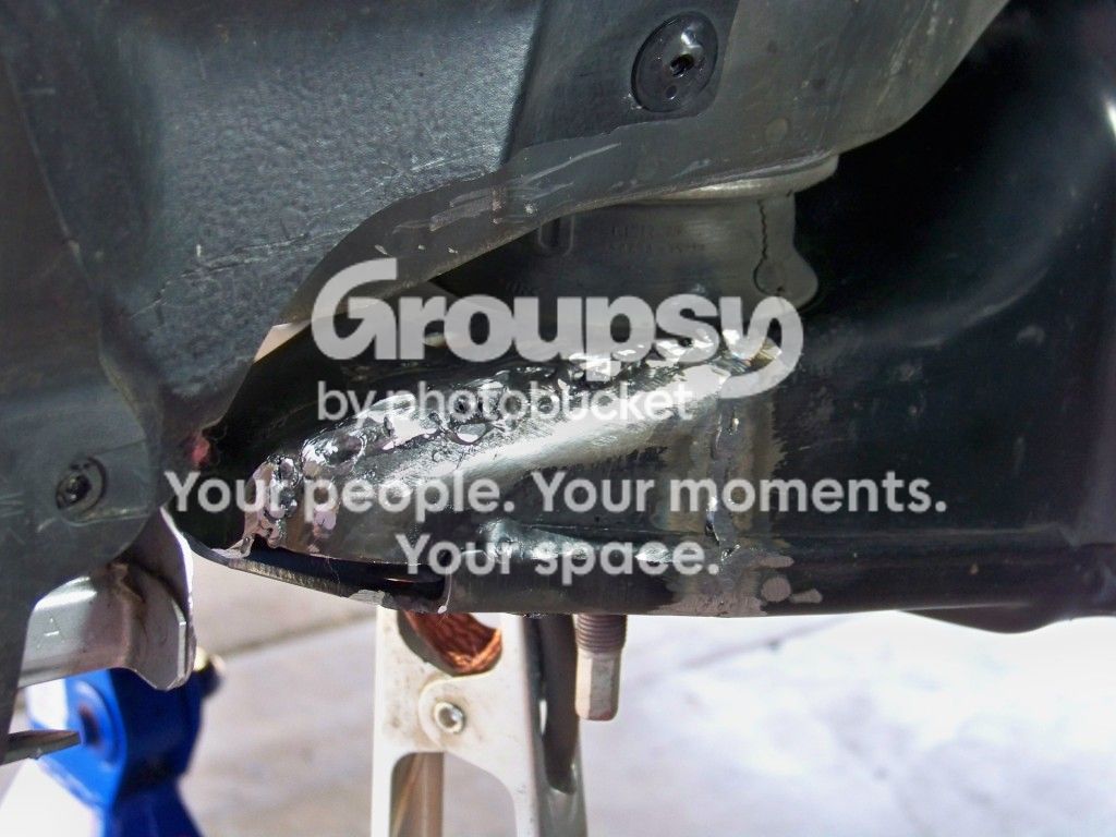
106_0920_zps27e19d88.jpg~original

Drivers side with the large gap I had to fill
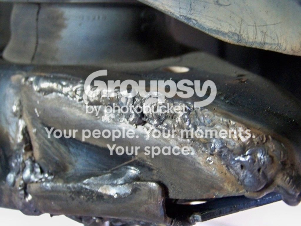
106_0931_zpsde0cf94f.jpg~original

106_0930_zps7887ef23.jpg~original

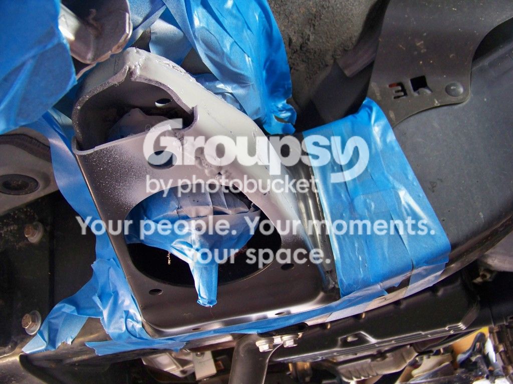
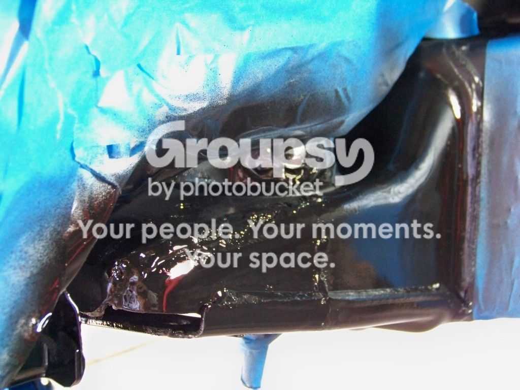
Once I got finished getting it all cleaned up and taped off I painted it. I used Rustoleum High Performance Primer and Gloss Black enamel.

106_0922_zps0ca735ef.jpg~original

106_0923_zps90fef681.jpg~original

106_0925_zps5b627642.jpg~original

106_0924_zpscd6a45b2.jpg~original

BAM!! No more rubbing.
2012-09-22_13-55-51_72_zps3f086a60.jpg~original

At full compression I was still able to have about 1/16” of clearance with the tires inflated to 35psi. If I air down, I’m sure it may rub a little bit at full lock and full compression, but not enough that I would get hung up. If I ever go up to 35s or so, I’ll most likely cut it way back, but that’s a while down the road. But enjoy!

Oh and here's a pic that made my truck feel small.
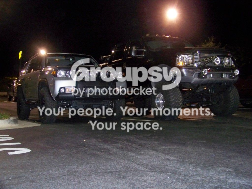
106_0906_zpsf0b1a0c6.jpg~original
 
Register to hide this ad
Looks good! Thanks for the write up.:thumb3:

Interesting theory on why the mounts are so long, seems logical though. Not to be critical as I can't weld at all, but maybe you could have ground down the welds to neaten it up a bit.

That Ford is a monster there is a guy near me with a very similar set-up, crew cab, 8' bed and like 12" of lift on 38's. Not very practical and IMO not very attractive. :nono:
 
If you don't mind me saying, I'm not sure those welds are functional at all. I'm a beginner as well, so maybe I don't know what I'm looking at, but I don't see penetration there - I see boogers. Probably fine for what you're doing there, but I wouldn't trust welds like that on something structural, is what I'm saying.

Not trying to be a jerk, because I'm just learning too, but hopefully offering some helpful feedback. :)
 
Looks good! Thanks for the write up.:thumb3:

Interesting theory on why the mounts are so long, seems logical though. Not to be critical as I can't weld at all, but maybe you could have ground down the welds to neaten it up a bit.

That Ford is a monster there is a guy near me with a very similar set-up, crew cab, 8' bed and like 12" of lift on 38's. Not very practical and IMO not very attractive. :nono:

The drivers side mount got cleaned up and ground down a lot more then the passenger side. Why you ask? I'm not really sure haha. I sprayed the passenger side mount with primer while I was doing the welding on the other side. When I finished and started grinding, I got it ground down some and was like damn, shoulda did this to the other side. The spray paint really hid most of it, and it didn't bother me enough to take the paint off and clean it some more. I just don't have pictures of the drivers side because my camera died in the midst of this project and figured I'd have enough to document it.

The guy with the ford I just think was having to overcompensate for something. I mean why else would you need a truck that big? He had maybe 4"s more of ground clearance than I did before he would smashed that front axle on something and scratched up those pretty Fox steering stabilizers

If you don't mind me saying, I'm not sure those welds are functional at all. I'm a beginner as well, so maybe I don't know what I'm looking at, but I don't see penetration there - I see boogers. Probably fine for what you're doing there, but I wouldn't trust welds like that on something structural, is what I'm saying.

Not trying to be a jerk, because I'm just learning too, but hopefully offering some helpful feedback. :)

Oh you big jerk!! haha I wouldn't trust the welds either for something structural. The bottom side of the mount was more or less a series of heavy tacks across the seam. I don't know if you have ever tried over head welding (or laid on your back welding up) but its a whole different animal. The weld just wants to glob and drip leaving holes in the work piece. I'm sure if I had used a different rod instead of the general purpose 6013 it might have worked a little bit better. The top welds, I made sure had proper penetration before I decided I liked the weld (from a function aspect).

If I had the choice, I would have used a mig welder and then the welds would have looked alot better. I bought my arc welder while I was taking a machining and welding class back in the spring and we had not learned Mig yet so I bought that Lincoln ac225.
 
Are we 100% sure? I have no clue but I do wonder about it.

The only load that I can think of that would be there, would be the load on the welds of where the body mounts and frame are connected.

I feel like the load would be closer to frame on the body mount if there was any, and not out on the wing jutting past the mounting location of the body mount.

I could be wrong though.

1E you got any insight on this??
 
The only load that I can think of that would be there, would be the load on the welds of where the body mounts and frame are connected.

I feel like the load would be closer to frame on the body mount if there was any, and not out on the wing jutting past the mounting location of the body mount.

I could be wrong though.

1E you got any insight on this??

I don't think your modifications changed the strength of the body mount at the point the body mounts to the bracket. Out near the tip yes you probably weakened it some. Why is it made that way? No idea but your guess of keeping the wheels from being driven backward is as good as any. It could also be used during assembly as a lift or locating point because of the additional hole near the tip. If you look at the rear body mount it is much shorter and supports the same load. Good job by the way!
 
I don't think your modifications changed the strength of the body mount at the point the body mounts to the bracket. Out near the tip yes you probably weakened it some. Why is it made that way? No idea but your guess of keeping the wheels from being driven backward is as good as any. It could also be used during assembly as a lift or locating point because of the additional hole near the tip. If you look at the rear body mount it is much shorter and supports the same load. Good job by the way!

Thanks!!
 
Are we 100% sure? I have no clue but I do wonder about it.
yes 100% had he modified the portion of the mount between the actual mount and the frame, maybe but even then it is only one mounting point he will be just fine

EDIT: same answer as given above
 
Welds

Nice job and I am no expert either as I haven't welded since high school back in the 80's. I do remember the acronym CLAMS though.

C - Current Setting
L - Length of Arc
A - Angle of Arc
M - Manipulation of the electrode
S - Speed of Travel

Also, DC is much easier than AC especially for vertical and overhead welds. And DC produces a better looking weld. The polarity also comes into play because when you are welding over head you want the current to travel from the rod to the base. If you are in AC you have the arc alternating (to rod and away from rod).

The type of rod also is a big factor too. A 6018 is the most common for learning (cost?) but requires some skill and practice to get a good bead. A 7018 rod is a better choice I think and just about lays a perfect bead with little manipulation.

Remember though, it doesn't have to look pretty to be functional. As long as you have good penetration and low impurities.

Miller - Welding Equipment - MIG/TIG/Stick Welders & Plasma Cutting is a good source of information.
 
The only load that I can think of that would be there, would be the load on the welds of where the body mounts and frame are connected.

I feel like the load would be closer to frame on the body mount if there was any, and not out on the wing jutting past the mounting location of the body mount.

I could be wrong though.

1E you got any insight on this??

Nice job on the BMC FactoryRide!Way to DIY!
I cut mine off very similar but didn't weld it back on.(no welder or welding skills,lol) I just left it open,cleaned it up by rounding off the corners,primed and painted. I may have somebody weld them up some day when I go to 35's but work just fine with my 34" tires now.Many on the FJ forum have just cut it and left it open as well as many others cut it off all the way to the rubber mounts and welded a rounded lip on it to look like the other 6. With 35's or bigger you will pretty much have to chop it all the way off to the actual rubber mounts.

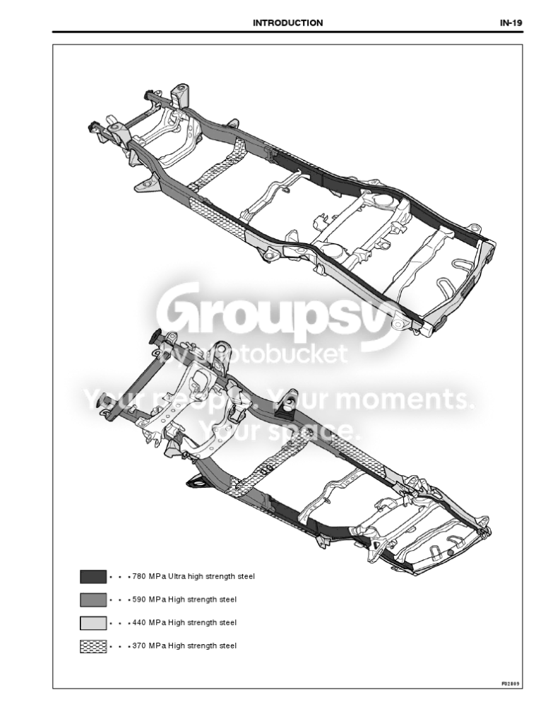
Here is the proof, IMO that they are for frontal/side crash protection and why those 2 are like that compared to the other 6 much smaller body mounts.Three mechanical engineers at work agreed during my research before cutting.Look at size and the steel tensile strength used there compared to the other 6.
frame.png~original


Here are pics of how I did mine and the clearance gained. Fully cycled and stuffed my front suspension offroad with no rubbing,so mission accomplished and still retained most of the crash protection,but did lose some I admit.

Here are pics of how I did mine
Tell tale signs of where it was rubbing
Picture002-10.jpg~original


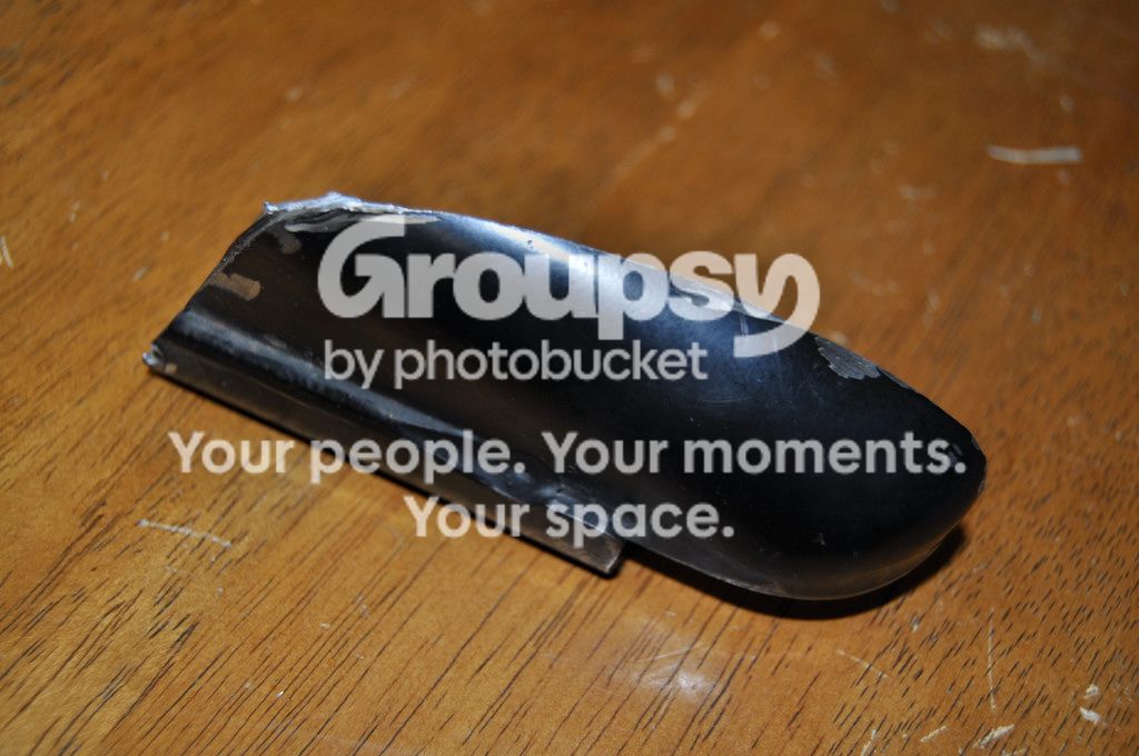
Piece of body mount I cut out.
Picture003-13.jpg~original


Clearance gained for bigger tires!
Picture016-9.jpg~original


Picture024-4.jpg~original
 
Last edited:
Nice job on the BMC FactoryRide!Way to DIY!
I cut mine off very similar but didn't weld it back on.(no welder or welding skills,lol) I just left it open,cleaned it up by rounding off the corners,primed and painted. I may have somebody weld them up some day when I go to 35's but work just fine with my 34" tires now.Many on the FJ forum have just cut it and left it open as well as many others cut it off all the way to the rubber mounts and welded a rounded lip on it to look like the other 6. With 35's or bigger you will pretty much have to chop it all the way off to the actual rubber mounts.

Here is the proof, IMO that they are for frontal/side crash protection and why those 2 are like that compared to the other 6 much smaller body mounts.Three mechanical engineers at work agreed during my research before cutting.Look at size and the steel tensile strength used there compared to the other 6.
frame.png~original


Here are pics of how I did mine and the clearance gained. Fully cycled and stuffed my front suspension offroad with no rubbing,so mission accomplished and still retained most of the crash protection,but did lose some I admit.

Here are pics of how I did mine
Tell tale signs of where it was rubbing

Makes perfect sense to me after looking at your drawing and steel spec Harper! Make that 4!
 
Nice job on the BMC FactoryRide!Way to DIY!
I cut mine off very similar but didn't weld it back on.(no welder or welding skills,lol) I just left it open,cleaned it up by rounding off the corners,primed and painted. I may have somebody weld them up some day when I go to 35's but work just fine with my 34" tires now.Many on the FJ forum have just cut it and left it open as well as many others cut it off all the way to the rubber mounts and welded a rounded lip on it to look like the other 6. With 35's or bigger you will pretty much have to chop it all the way off to the actual rubber mounts.

Here is the proof, IMO that they are for frontal/side crash protection and why those 2 are like that compared to the other 6 much smaller body mounts.Three mechanical engineers at work agreed during my research before cutting.Look at size and the steel tensile strength used there compared to the other 6.
frame.png~original


Here are pics of how I did mine and the clearance gained. Fully cycled and stuffed my front suspension offroad with no rubbing,so mission accomplished and still retained most of the crash protection,but did lose some I admit.

Here are pics of how I did mine
Tell tale signs of where it was rubbing
Picture002-10.jpg~original


Piece of body mount I cut out.
Picture003-13.jpg~original


Clearance gained for bigger tires!
Picture016-9.jpg~original


Picture024-4.jpg~original

Thanks Harper!
I had originally thought about just rounding the edges. I decided to weld it because I was like, I bought the welder, why not use it haha. The cut you made looks very similar to one of the cuts I made!

Whenever I do step up to 35's it'll be modified again. Hopefully with some better welding skills by then.

And thanks for those pics of the research! That's really cool!
 
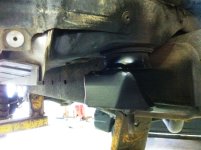
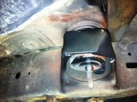
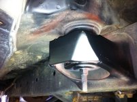
This is what we do at the shop. Cut, grind, make plates, weld, grind, prime, and paint.
Here's the finished product.
IMG_0714.jpg

IMG_0715.jpg

IMG_0716.jpg
 

Attachments

  • IMG_0714.jpg
    IMG_0714.jpg
    118 KB · Views: 3,688
  • IMG_0715.jpg
    IMG_0715.jpg
    57.5 KB · Views: 3,667
  • IMG_0716.jpg
    IMG_0716.jpg
    117.5 KB · Views: 19,910

Members online

No members online now.

Forum statistics

Threads
278,306
Messages
3,554,045
Members
248,016
Latest member
Advally Service

Trending content

Back
Top