Cam and Crank Sensor Question.

Troybylt

New member
I will be doing my timing belt/water/radiator etc very soon and since I'm going to have the whole front of the motor off and radiator and fan shroud cleared out I wanted to know if it would be worth it to replace the cam angle sensor and crank angle sensor.

Nearly 225k on the clock, no idea if they've ever beer replaced, I tried using search but couldn't fine what I was looking for, how reliable are these sensors, enough so that I should leave them alone?

If I do leave them be, and they end up going bad, how much of a pain are are they to change?

Do we even have a crank angle sensor?
 
Register to hide this ad
Crank sensor is located down toward the bottom front of the engine, and is controlled by little teeth on the crank sprocket.


From all the years of reading the internet and owning a 4runner, I've never seen either fail, or at least not as frequently as practically any other sensor on the car.


If it were me, I'd leave them alone until they need replacement... I didn't touch mine when I did the TB/WP...
 
[MENTION=100832]Troybylt[/MENTION]

^^^^what he said. I've got a few miles on mine and few timing belt changes. Sensors have never failed. Replace the cam and crank seals while you're in there.
 
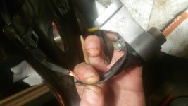
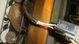
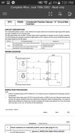
Sorry to revive an old thread but I can't find an answer by searching and I'm a new member so I can't start a new thread. Do our cam position sensors use all three wires or is the ground wire just there for other applicable vehicles that require one? Mine is clipped at both ends of the rubber sleeve that the three wires run through. Looking at replacements online there's 3 wires coming off the sensor/mount and 2 wires going into the clip at the end. Any thoughts?
 

Attachments

  • 20181018_032442.jpg
    20181018_032442.jpg
    123.9 KB · Views: 8,330
  • 1540081550475529321008.jpg
    1540081550475529321008.jpg
    118.4 KB · Views: 7,921
  • Screenshot_2018-10-20-19-30-12.jpg
    Screenshot_2018-10-20-19-30-12.jpg
    116.8 KB · Views: 7,588
Can’t believe there isn’t a code being thrown for such.

If I were in your shoes, solder or butt connect it and go from there.
 
Any chance it's just a support cable for the other two? It would explain why my truck was running fine up until disassembly as well as the lack of that wire/cable coming out on the other side of the heat shrink (it looks clipped flush with the sleeve), the fact that it's not in any pictures of new ones on the clip side of the heat shrink and why from the looks of it, at least through my completely unknowledgeable eyes, there's only two wires shown in the fsm diagram. It's also shorter than the other two therefore taking more strain and made out of what looks like steel wires twisted around some nylon and a rubber sleeve. Not really sure but I kinda had the impression steel wasn't that conductive of a metal. Probably going to just try it as is and then replace if necessary but can anyone confirm this?
 
Is it supposed to connect to anything beyond the heat shrink or does running along side the other two for a distance prevent the electrical interference?
 
grounded at both ends.

if you have no problems now, i would not worry about it. Electrical Interference on a VR (variable reluctance) sensor is not usually a gray area thing (if it works now, spent your time and effort somewhere else). OEM ECU have very good filters for it also. i share this from several megasquirt projects i've done which used to be rife with interference issues.

you can twist the 2 signal wires for interference protection also.

of course i would go crazy and solder the connections back in and wire it as it was designed so i could stop thinking about it.
 
I appreciate the feedback. The only thing I'm still trying to wrap my head around is if this is a ground wire then where would it connect and with what? Every single picture online that show the end of the pigtail only show two wires. It does look grounded through the attachment point on the sensor bracket but I can't find any evidence of that wire continuing beyond the heat shrink. Any chance all that's needed for it to prevent interference is to ground out and simply run along side the signal wires?...kinda like what you were saying about twisting two signal wires together? That would make the most sense from what I'm seeing if it's possible it works that way. I always thought of wires are having to go from one thing to another but I suppose in the case of electrical interference proximity could be enough. Am I understanding correctly?
 
that picture shows it pretty clearly only on one end.

i clicked the goog a couple times out of curiosity, it seems that some designs in the audio world only ground one end to avoid problems of grounding into a ground loop, but seems people agree best practice is to ground at the source end like it is, and ensure the termination end is a central ground.

in short, it seems that it's only grounded at the sensor end and shielded through that first connector.
 

Members online

Forum statistics

Threads
278,307
Messages
3,554,054
Members
248,016
Latest member
Advally Service

Trending content

Back
Top