Cluster to ECU speed signal question.

1bzdvl

Member
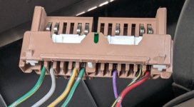
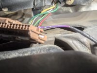
Hi all. I'm still trying to figure out my p0500 issue. I am trying to test for signal pulse from the gauge cluster to the ECU. According to the wiring diagram, the purple wire is how that signal gets sent. I pulled the wire from the ECU plug to test with a multimeter and only expected to see measurable voltage when the truck was moving. Instead, I'm getting 14v from the wire continuously while the truck is running. I've run an wire that is independent of the harness to test if the wire had a short. No change. Any help and insight is appreciated.

2000 SR5 5 SPD 3.4

TIA

I'll add that I have recently added a stock elocker setup and used Timmy's video to swap and wire.
 

Attachments
  • PXL_20250403_021213980.RAW-01.MP.COVER~2.jpg
    PXL_20250403_021213980.RAW-01.MP.COVER~2.jpg
    119.9 KB · Views: 847
Last edited:
Register to hide this ad
Year, trim, engine and transmission might be helpful here... ABS equipped or not? Hard to do any remote diagnostics without information.

-Charlie
 
Year, trim, engine and transmission might be helpful here... ABS equipped or not? Hard to do any remote diagnostics without information.

-Charlie

It's a 2000 SR5 with the 3.4 and 5spd. Definitely should have added that. Thank you.

Speedometer is working. The voltage I'm getting at the wire seems to be blocking the signal. I've already replaced the cluster as I thought that was my initial issue.
 
ABS equipped trucks from that year use the Green-Orange wire from the cluster to drive all other speed signals in the truck (ECU, Diff lock, 4WD ecu, cruise control, etc.). Same connector you have up there, pin 3.

If you found a purple-blue wire at the ECU, it is the heated oxygen sensor output from the ECU to the front O2 sensor on a Federal Emissions 4Runner... The speed signal comes in on a completely different connector there (from the dash harness, not the engine harness).

-Charlie
 
ABS equipped trucks from that year use the Green-Orange wire from the cluster to drive all other speed signals in the truck (ECU, Diff lock, 4WD ecu, cruise control, etc.). Same connector you have up there, pin 3.

If you found a purple-blue wire at the ECU, it is the heated oxygen sensor output from the ECU to the front O2 sensor on a Federal Emissions 4Runner... The speed signal comes in on a completely different connector there (from the dash harness, not the engine harness).

-Charlie

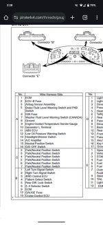
Hi Charlie. I want to say thank you for giving some of your time to help me out. I looked at pin 3, and I don't have any wire there, nor do I see an orange/green wire. Maybe due to my truck having a J shift transfer case? I've included the cluster diagram for my truck in the FSM. Pin 3 does go to the 4wd control ECU, but pin 9 goes to the ECM. I put my multimeter on each pin, and I only get voltage at pin 12. That makes sense as that goes to the gauge fuse. I'm completely lost at this point.
 

Attachments

  • PXL_20250403_210619065.RAW-01.MP.COVER~2.jpg
    PXL_20250403_210619065.RAW-01.MP.COVER~2.jpg
    134.2 KB · Views: 866
  • Screenshot_20250403-142808.jpg
    Screenshot_20250403-142808.jpg
    140.9 KB · Views: 1,613
  • Screenshot_20250403-130134.jpg
    Screenshot_20250403-130134.jpg
    136.2 KB · Views: 830
Last edited:
Hi Charlie. I want to say thank you for giving some of your time to help me out. I looked at pin 3, and I don't have any wire there, nor do I see an orange/green wire. Maybe due to my truck having a J shift transfer case? I've included the cluster diagram for my truck in the FSM. Pin 3 does go to the 4wd control ECU, but pin 9 goes to the ECM. I put my multimeter on each pin, and I only get voltage at pin 12. That makes sense as that goes to the gauge fuse. I'm completely lost at this point.
Ah, you are on the wrong connector then. The violet wire you have there on that connector (notice, NOT purple) is the check-engine light wire. I assumed you were on the right connector and should have looked deeper. I also assumed you saw a stripe on that wire, but there is none...

The connector you need is the smaller of the two dual-row connectors on the cluster. And you need the Green-Orange wire (green with orange stripe), not the Orange-Green wire (orange wire with green stripe). Pin 3, top row, next to the lock tab.

You even posted a screenshot with the information... though it was cut off on the bottom right of the image.

-Charlie
 
Ah, you are on the wrong connector then. The violet wire you have there on that connector (notice, NOT purple) is the check-engine light wire. I assumed you were on the right connector and should have looked deeper. I also assumed you saw a stripe on that wire, but there is none...

The connector you need is the smaller of the two dual-row connectors on the cluster. And you need the Green-Orange wire (green with orange stripe), not the Orange-Green wire (orange wire with green stripe). Pin 3, top row, next to the lock tab.

You even posted a screenshot with the information... though it was cut off on the bottom right of the image.

-Charlie

Holy crap Charlie,

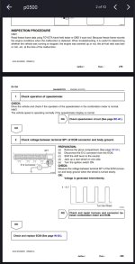
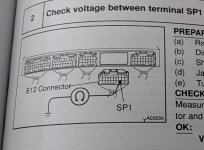
I've been using a digital copy of the FSM that's covers multiple years. I just pulled out my 2000 specific hard copy, and the ECU test point for speed pulse is on a completely different plug.

I'll report what I find. Thank you so much for walking me through this!
 

Attachments

  • PXL_20250403_224534845.RAW-01.MP.COVER~2.jpg
    PXL_20250403_224534845.RAW-01.MP.COVER~2.jpg
    128 KB · Views: 835
I really pays to have the Correct FSM for the Correct year. Glad Charlie got you on the correct path. :-). He is always a valuable resource. Good to have on the forum here.
 
Ah, you are on the wrong connector then. The violet wire you have there on that connector (notice, NOT purple) is the check-engine light wire. I assumed you were on the right connector and should have looked deeper. I also assumed you saw a stripe on that wire, but there is none...

The connector you need is the smaller of the two dual-row connectors on the cluster. And you need the Green-Orange wire (green with orange stripe), not the Orange-Green wire (orange wire with green stripe). Pin 3, top row, next to the lock tab.

You even posted a screenshot with the information... though it was cut off on the bottom right of the image.

-Charlie

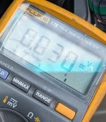
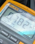
Now that I've found the right wire to test, I can verify that I am getting some signal to the ECU from the cluster. The reading at .03 V is at a stop, .78 while moving. I was expecting to see something more in the range of 4 to 6 volts. At least that's what the FSM describes. Maybe it's reading that low due to my multimeter, or the connection I've made.
 

Attachments

  • PXL_20250403_235721454.RAW-01.MP.COVER~2.jpg
    PXL_20250403_235721454.RAW-01.MP.COVER~2.jpg
    135 KB · Views: 763
  • PXL_20250403_235543444.RAW-01.MP.COVER~2.jpg
    PXL_20250403_235543444.RAW-01.MP.COVER~2.jpg
    133.2 KB · Views: 756
Put it in AC mode and the value should go higher. You are testing an alternating signal, and the positive part of the waveform might be short (haven't looked at that one myself).

I'm familiar with this one since I went from the base small ~29" tires up to ~32" tires and installed a speedometer correction unit - but that gets installed between the ABS computer and the cluster, not on the output side of the cluster.

-Charlie
 
Piggybacking off this thread to ask if anybody knows what what would cause my tachometer, speedometer, and backlighting to flicker/not work? It's not related to temperatures, bumps in the road, or trip run time. I've checked everything I know how to check but I'm not sure about checking/diagnosing the ECU or cluster as bad
 
Piggybacking off this thread to ask if anybody knows what what would cause my tachometer, speedometer, and backlighting to flicker/not work? It's not related to temperatures, bumps in the road, or trip run time. I've checked everything I know how to check but I'm not sure about checking/diagnosing the ECU or cluster as bad
Just the cluster backlighting or all dash lighting?

If you can make it worse, you can make it better. Get all the plastics out of the way and see if directly manipulating things (connectors, flex PCB, etc.) around the cluster makes any difference.

-Charlie
 
Put it in AC mode and the value should go higher. You are testing an alternating signal, and the positive part of the waveform might be short (haven't looked at that one myself).

I'm familiar with this one since I went from the base small ~29" tires up to ~32" tires and installed a speedometer correction unit - but that gets installed between the ABS computer and the cluster, not on the output side of the cluster.

-Charlie

I'll give that a shot. I'm thinking I'll test the voltage back probing the plug at the cluster. See if it's significantly higher there.
 
Put it in AC mode and the value should go higher. You are testing an alternating signal, and the positive part of the waveform might be short (haven't looked at that one myself).

I'm familiar with this one since I went from the base small ~29" tires up to ~32" tires and installed a speedometer correction unit - but that gets installed between the ABS computer and the cluster, not on the output side of the cluster.

-Charlie

I finally had some time to tinker again. I went through the FSM procedure for testing by turning the key to 'run', raising a rear wheel and spinning it by hand. Highest voltage I recorded at the ECM side was about 1.6v. I then did the same procedure pinned at the cluster, and saw the same voltage. I'm dreading that this is an ECM issue.
 
I finally had some time to tinker again. I went through the FSM procedure for testing by turning the key to 'run', raising a rear wheel and spinning it by hand. Highest voltage I recorded at the ECM side was about 1.6v. I then did the same procedure pinned at the cluster, and saw the same voltage. I'm dreading that this is an ECM issue.
A multimeter in DC autorange mode will not catch the speed sensor pulses correctly. Use AC mode and spin those tires a bit faster. It is a 0-5V signal, which is 1.8Vrms if it was a sine wave, though as a square wave, it should read higher than that. If the pulses are coming to slowly (spinning the tire slowly), then even in AC mode it will read lower than 1.8Vrms.

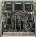
Though rare, it is possible to have capacitor issues in the ECU. It might be worth opening it up and inspecting for physical damage. Otherwise, the ECUs are VERY reliable.

-Charlie
 
A multimeter in DC autorange mode will not catch the speed sensor pulses correctly. Use AC mode and spin those tires a bit faster. It is a 0-5V signal, which is 1.8Vrms if it was a sine wave, though as a square wave, it should read higher than that. If the pulses are coming to slowly (spinning the tire slowly), then even in AC mode it will read lower than 1.8Vrms.

Though rare, it is possible to have capacitor issues in the ECU. It might be worth opening it up and inspecting for physical damage. Otherwise, the ECUs are VERY reliable.

-Charlie

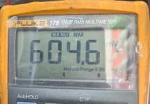
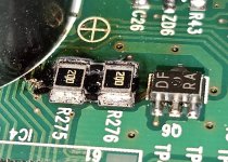
Alright. So this is what I'm reading before I get the wheel spinning at a certain speed. I'm including a photo of my original cluster. There was damage on the board, so I replaced the cluster and swapped the chip with the odometer info so I have the original mileage still. The computer board looks just fine. Nothing seems suspect. Once again, thank you for taking the time to help me.

Richard
 

Attachments

  • PXL_20250408_185949536.RAW-01.MP.COVER~2.jpg
    PXL_20250408_185949536.RAW-01.MP.COVER~2.jpg
    131.3 KB · Views: 156
  • PXL_20241201_185745370.LONG_EXPOSURE-01.COVER~2.jpg
    PXL_20241201_185745370.LONG_EXPOSURE-01.COVER~2.jpg
    135.4 KB · Views: 163
  • 20240828_162654~2.jpg
    20240828_162654~2.jpg
    140.4 KB · Views: 156
Alright. I just went and put my meter on pin 11 of connector 'A', to check signal from the ABS ECU. Measured 12v at rest and got as high as 17v driving. I'm going to assume I replaced my bad cluster with a used bad cluster and am taking a trip to the local speedometer repair shop. I'll post results as they come. Thank you.
 
Last edited:

Members online

Forum statistics

Threads
278,312
Messages
3,554,089
Members
248,016
Latest member
Advally Service

Trending content

Back
Top