Constant 12V power outlets

i'm trying to do the same thing. the original post is helpful but the setups are different for the 5th generation.

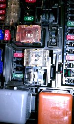
since i rock an SR5, there isn't a relay for the power outlets/inverter. the relays are in the engine compartment and, according to the diagram on the reverse of cover and manual, there is only a space for and 80A relay/fuse for the inverter.

this is where the jumper goes but i don't know how to do it: slide it over the contacts?

you can check out the picture.

any help would be appreciated.

thanks.
 

Attachments

  • IMAG0286.jpg
    IMAG0286.jpg
    144.6 KB · Views: 1,724
Ok...from a 12V persons standpoint..there are problems and great ideas in this..


My honest suggestion is that, that relay you have a hold of has a low-current circuit, and the high current circuit (the one you jumped) Use them and put a switch on it

Sorry i cant post pics to what im gonna describe, but i have a 3RD gen and i dont know if its the same back there..

Btw...i dont have a 3rd gen, and cant check that relay, how i am going to explain it is one way, but you could do it many other ways, if someone wants to send me one of their relays (if they just jumped the connections) i can test it and send them it back...
Furthermore, im not responsible if you zap, shock, blow fuses, or anything else ..im doing this off of my head...

Parts needed:
16 or 14 gauge wire (14 is better) (this is for the jumper)
Male spade terminals (get ones that the spade is the same size as the ones on the factory relay)
Female spade terminals (matching size to the male ones
Fuse holder
1 amp fuses
Solder / soldering iron
Tools to get to the fuse
Crimpers
electrical tape or heat shrink tubing
18 or 16 ga wire (to power the switch)


Start by removing everything as the O.P. described


Pins 1 and 3 (see diagram below)are you low-voltage activation wires

Pins 3 and 5 are your "high current" wires...

Here is what we are going to do, hook up your existing relay, to a switch so you can decide to keep the power on, or off, so if someone does need to power something when the car is off, you can just, flick a switch..

Below is a two diagrams:
acc_mod.jpg

acc_mod_diagram.JPG


1.make your "power cable"
using your minimum 18 ga wire, make the cable long enough to go from wherever you are getting power from to the switch (make it an extra foot or two longer for slack)

2.solder your fuse holder onto one side of the wire and solder the other side of the wire the switch, cover your connections (electrical tape, or heat-shrink tubing)...

3.Solder a wire to the other terminal of the switch, make sure it has enough room to go from the switch, to where your mounting that factory relay and mayb a little extra, and crimp on a female spade connector to the loose end

4.You will need to make two jumper wires...16ga or 14ga the thicker the wire the better (better safe then sorry). Simply make the two wires long enough to go from the factory relay socket, to where you are mounting the relay... strip both ends of both wires, and crimp on female spade connectors on the side going to the relay and male spade connectors on the other side...

(Be carefull on this next step, if your battery is hooked up, these wires could be "hot" DONT LET THEM TOUCH ANYTHING

5.Install the male side of one jumper cable into the factory socket pin 3, and the second jumper wire male side in the factory socket pin 5.

6.Connect the female spade of one jumper cable onto the factory relay pin 3, and the second jumper wire female side on the relay pin 5

7.Grab your switch (which should have your "power cable" soldered onto it, and a wire soldered to it with a female spade connector.. )Plug the female spade onto pin 1 of the factory relay

8.Now, make a wire that has a female spade connector on one end, and a ring termail on the other, this will be your ground wire. Connect the female spade connector to the factory relay, and ground the other end by securing it to some metal (easy place is the sheet metal in the drivers kick panel) by screwing it in (use a star washer to lock the screw in...) with a self-tapping screw...


Double check all your connections, cover all bare wire connections, and mount your switch...


9.Connect the power cable to a constant +12 volt line (you can even use the power from one of the two jumpers your installing if your feeling a little advanced(you would need to test which one is power..like i said, i dont have one, cant test it))

You should be able to hear the relay click if you flick the switch back and forth, and your cigarette lights will switch between constant and switched power...

You now have a switch to select the power to the lighter plugs to be constant or accessory...


Anyone do this knowing it will work? What if you want switch for constant power to all accessories?i.e. radio.
 
Took a quick read on this thread. I haven't done the mod myself but I do have 10+ years of 12V experience and a bachelors and masters in EE. Something about the results from the thread doesn't seen right to me.

- First, my assumption is that the OP has bridge the high amp side of the relay. In a standard SPDT relay, this would be terminals 87 and 30. Generally speaking, either 87 or 30 is a fused 12+ constant. Bridging these terminals, you will effectively get 12V constant on the other pin.

- By this assumption, only the loads (accessories) that are on that circuit should light up. I don't understand why things like the compass comes on. Unless they on this circuit, but if this is true then why do some members have the compass on and others do not? (maybe different years or maybe some members just do not have the electronic compass.)

- If the compass is not on the same circuit, then perhaps some members are jumping the wrong terminals (i.e. 87 to 85 or 87 to 86.) But if that's the case then the outlets will not work.
 
Like a previous poster, I'm curious if these mods are exactly the same on a 5th Gen. The electrical stuff is a little out of my comfort zone, so I want to be 100% sure this works on my 2011 Limited before I get in over my head!

Thanks in advance, and thanks for the easy to follow instructions!

Ditto. Has anyone with a 5th gen succeeded in finding the relay and completing this mod? I have been told it is the ACC Relay on the 5th gen's and is under the driver's side dashboard, but my '10 Limited has a knee airbag at the bottom of the cover and I'm hesitant to try to take that cover off without some assurance that I'm on the right track and the airbag isn't going to explode in my face.
Any help?
 
Ok, so I just bought an 08 limited and dove right in and did a couple electrical mods on my weekend and I'm having a couple issues... After I finished these mods my right turn signals do not activate, nor does my power defrost button. After reading another post earlier in this thread, I suspect that my rear wiper will not be working either.

The first mod that I did was the fog light mod. In following the write-up I connected prong #2 on the fog light relay to the 25amp seat heater fuse via add-a-circuit, as I had an IG relay and was unable to use that connection. The second part of the write-up I followed exactly. Fog lights worked beautifully, exactly as intended. I did not think to test anything after this to see if I had lost function of any other electronics.

Next, I did the 12v constant power mod. Super simple mod, followed the directions to remove the DC SKT relay and place a jumper wire from pins 3 to 5. 12v front and rear units now worked without the key being in the ignition. Still didn't test anything to see if I had lost function of other electronic connections.

Last, I tried the 115V constant power mod. Similarly to the fog lights mod, I connected pin #2 on the ACC INV 115v Relay with the AC 115V INV 15amp fuse via add-a-circuit. I then pulled out the jumper wire I had just inserted in place of the DC SKT relay and created a new one with an extra lead coming off to be connected with the yellow wire with a red stripe coming off the 115v AC switch in the dash (per the write-up). I connected the jumper, cut the yellow/red wire on the switch, taped off the portion leading up to the dash and connected the lead from the jumper to the yellow/red wire connected to the switch using another blue 3m Scotchlok Electrical IDC connector.

Here's where problems started happening:
I depressed the 115v AC switch and the light came on the switch, but no power to the actual plug. 12v sockets both still had power, I didn't test the fog lights but in the end they still worked the same.

I tried two things next, but I can't remember which yielded what results. I tried reconnecting the yellow/red wire with it's original other half, and then touching the lead from the DC SKT jumper to that connection. It didn't work the way I wanted, so I pulled the ACC INV 115v relay and add-a-fuse going to the AC 115V INV 15amp fuse. The result was power to the 115v inverter, but my center display (clock, outside temp, heater/fan read-out) and my temperature controls were also energized without the key. I replaced the ACC INV 115v relay with the untouched DC SKT relay so it would be back to stock, and I reconnected the yellow/red wire with itself (basically un-doing the mod).

12v sockets still had constant power, fog lights still worked the way the mod intended. That's when I noticed my right side turn signals (front and rear) did not actuate when engaged. My emergency lights work fine, brake lights work fine. Front running lights work fine. Just the turn signal. And defrost button, and probably rear wiper (I'll update when I get home tonight).

I'm not an electrical genius so any help would be greatly appreciated.
Thanks!
 
Just undid all 3 mods, completely back to stock, still having turn signal, defrost, and rear wiper issues. None of them work. ****. :moping:
 
Finally did this mod so that my fridge can keep running while camping and stopped.

The only thing that I did different was rather than just a jumper wire between the two pin locations I ran them up to the dash and wired them to an illuminated SPST switch so I can turn the power flow on and off. Nice since I can turn it off when the vehicle is sitting with no food in the fridge and not need to worry about anything else drawing power. I do have dual batteries and my fridge does have automatic shut down if power gets too low, but better safe than sorry!
 
So I feel a little dumb. After cutting power to your vehicle you have to "normalize" all the windows before stuff like your wipers, auto up/down, and defrost start working again.

That just means putting them all the way down and all the way back up again. So that fixed the defrost and rear wiper issues.

Got back into the wiring harness directly under the steering wheel and found the right turn signal wire (edit: green and yellow), played around with it and got intermittent connection. Then the wire broke in two. :/

Touch the two ends, perfect strong connection. Bingo. Wired back together, no issues since. Did all this a day or so after my last post so it's been fine for a while now.
 
Ditto. Has anyone with a 5th gen succeeded in finding the relay and completing this mod? I have been told it is the ACC Relay on the 5th gen's and is under the driver's side dashboard, but my '10 Limited has a knee airbag at the bottom of the cover and I'm hesitant to try to take that cover off without some assurance that I'm on the right track and the airbag isn't going to explode in my face.
Any help?

I did a 12v constant on mod on my 5th gen, but because I didn't want to dig into the relay box which is fairly well up under the dash, I took the quick and easy way out. Cheap, fast, easy... Not /quite/ as nicely permanent as the relay mod, but I can dig into that some other time if I'm really bored :) This work fine for now...

http://www.toyota-4runner.org/5th-gen-t4rs/165542-warthog-build-adventure-thread-2.html
 
Could you put a switch on the jumper so you have power while the car is off when you press the switch, but don't otherwise? How would you wire this? Sorry, I'm electrically illiterate.
 
Could you put a switch on the jumper so you have power while the car is off when you press the switch, but don't otherwise? How would you wire this? Sorry, I'm electrically illiterate.

Yes. The switch would just be inline with the jumper.

Instead of this:
PinA---------PinB

you would have this:
Pina----Switch----PinB

Edit: sorry...that's a little simplistic, and there would be no power to your outlet when the switch wasn't turned on. You would really need a SPDT switch...one that basically has 2 different "on" positions. One that keeps it the factory way, and one wired like my second diagram.
 
9) Construct jumper wire.

When you say "construct jumper wire", do you mean literally assemble/construct the object you have pictured? Or can I walk into a hardware or automotive parts store and buy a jumper wire premade that looks like that?

Dumb question, I know. But I'm automotive-electronically dumb. :)

Do jumper wires come in male and female?


dt
 
When you say "construct jumper wire", do you mean literally assemble/construct the object you have pictured? Or can I walk into a hardware or automotive parts store and buy a jumper wire premade that looks like that?

Dumb question, I know. But I'm automotive-electronically dumb. :)

Do jumper wires come in male and female?


dt

You make the jumper yourself. you use a 3 inch piece of 14 gauge wire and crimp on a .250" male solderless terminal to each end.
 
And after 2+ years I finally did this!

All this work for just one little fuse..

Next up is the VSC traction control bypass! Thanks for this
 

Members online

No members online now.

Forum statistics

Threads
278,309
Messages
3,554,071
Members
248,016
Latest member
Advally Service

Trending content

Back
Top