Controlling Additional Lights with Puddle Lamp Circuit - Done....Safely!

Hopefully you can help me out.
I have a 2017 TRD Off Road that did not come with puddle lights in the mirrors.

Mine does not have the white wire for the mirror puddle lamp in this plug.

Using a volt meter, I discovered that pin always has 11.23 volts to the pin where the white wire would be.
And when I unlock the door with the remote, that 11.23 volts ramps up to 12.66 volts, and then back down.

Instead of messing with the mirrors, I'd like to put lights under the rocker panels.

Is there a negative switch wire for this puddle lamp circuit?

Any help appreciated.
Tom S.

It is odd that the voltage is at 11.23V. Not sure why this is. I am not familiar with TRD's. However, being always "hot" I do not think you can use this for relay control. On my Limited this pin is 0V and then ramps up to 12V for puddle lamp illumination. The ramp up occurs with push of unlock button on remote or when I simply approach the truck with remote in my pocket since I have the keyless entry/start.

If I recall the dome light circuit is negative switched. I believe I came across several threads stating this during my initial research on adding my rock/accent lights.

When looking at sources, just be careful as some circuits may be direct outputs from computer, like the OEM puddle lights, and not normal battery-fuse-relay/switch setup. Thus any kind of short, back feed, or current overdraw could possibly damage the computer and result in costly damage.
 
Last edited:
Great idea. Is there anything you would change after using it for a while? What switch did you end up using?

For the control circuits....no changes. Everything working fine. I am using one of the circuits in Switch Pro system for the switch control. Here is a thread describing the system, or google Switch Pro for manufacturer website.

http://www.toyota-4runner.org/5th-gen-t4rs/223646-switch-pro-8100-mounting-location.html

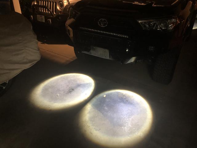
The only thing I may change is moving the lights to a location lower, or closer to the ground. to get more light spread on the ground beyond the perimeter of the vehicle. You can see my pictures where there is a sharp cutoff of the light just barely beyond the perimeter of the vehicle. I like for the light to extend further out.
 
It is odd that the voltage is at 11.23V. Not sure why this is. I am not familiar with TRD's. However, being always "hot" I do not think you can use this for relay control. On my Limited this pin is 0V and then ramps up to 12V for puddle lamp illumination. The ramp up occurs with push of unlock button on remote or when I simply approach the truck with remote in my pocket since I have the keyless entry/start.

If I recall the dome light circuit is negative switched. I believe I came across several threads stating this during my initial research on adding my rock/accent lights.

When looking at sources, just be careful as some circuits may be direct outputs from computer, like the OEM puddle lights, and not normal battery-fuse-relay/switch setup. Thus any kind of short, back feed, or current overdraw could possibly damage the computer and result in costly damage.

I just noticed that on your original thread that rigtec mentions the white wire as the hot, and the white with black wire as "negative path" to turn on. So apparently negative switched like the dome light. So I just need to test for that negative ECU switched wire.

I'm starting with no mirror puddle lights and just want to add them.

Thanks for your warning. I really don't want to smoke the ECU.
 
Beach5150;2745302]I just noticed that on your original thread that rigtec mentions the white wire as the hot, and the white with black wire as "negative path" to turn on. So apparently negative switched like the dome light. So I just need to test for that negative ECU switched wire.

I'm starting with no mirror puddle lights and just want to add them.

Thanks for your warning. I really don't want to smoke the ECU.[/QUOTE]

You definitely want to test the wires and not damage the ECU. Thanks to [MENTION=83083]rigtec[/MENTION] for documenting! The white wires with black stripes that I have tested have been ground. The ground wire completes the circuit to activate the dome thus negatively switched.
 
I'm not saying I would do this anytime soon (too many projects right now), but I wanted to be sure to tell you, [MENTION=4307]matoolie[/MENTION], good job on the wright up! I am putting this in my back pocket for a possible winter project since I have all or most of the parts already.

Cheers!
 
Did you get this project done and how did it turn out? Most pics are gone from the original post.

If only I were a time bandit......
No I haven't stolen any free time lately to do this one, but will probably be getting parts slowly ordered, sent back, re-ordered and waiting for when the time does come. I'm sure the BD rock lights won't disappoint
 
I have been looking into doing this for a while now, I have an SR5 without puddle lights, do you know if this would change for me if I were to pursue it using your method?

I know this is an old thread but I just tested this and have an answer.

Really want to do this and I have an SR5.

I was thinking there is no way Toyota is printing different PCBs or whatever for ECUs for the different trims. So I stuck a probe in where that white wire should be. Sure enough, I observed the voltage ramp. So the SR5 (and presumably the TRD PRO as someone else mentioned) have the same pins back there but lack the rest of the wiring.

I am going to work off OP's design and try to get this done. Let you guys know. Plan is to add a pin to that connector and then build basically the same wiring.
 
I know this is an old thread but I just tested this and have an answer.

Really want to do this and I have an SR5.

I was thinking there is no way Toyota is printing different PCBs or whatever for ECUs for the different trims. So I stuck a probe in where that white wire should be. Sure enough, I observed the voltage ramp. So the SR5 (and presumably the TRD PRO as someone else mentioned) have the same pins back there but lack the rest of the wiring.

I am going to work off OP's design and try to get this done. Let you guys know. Plan is to add a pin to that connector and then build basically the same wiring.

I have a 2017 Off-Road that also didn’t come with mirror puddle lights.
I’ve done some testing and temporarily connected one of those rock lights to where that white wire should be, and a ground. It does work great & ramps down.
Not sure if I’ve found the correct connector, but I know it will work.
 
A little update.....the system continues to work well. No issues.
I have however replaced the 4 lights I got from Amazon with a Rough Country 4 LED rock light kit. Nice lights. Much brighter, but more focused light. More expensive, but still reasonable cost. I have the lights aimed more toward tires so there is a dead spot in the middle.

Also used another of the same 4 light kit for 2 backup lights in rear and 2 lights in front just for the heck of it. These are not on the puddle light circuit, but controlled by another circuit on my Switch Pro.

Puddle lights
B455-F7-AB-798-A-40-E1-96-BB-00-A7-A035-C8-EA.jpg


Backup lights
5-F7-EEAC6-D786-43-B1-85-C5-87007-D8490-E7.jpg


Front lights
E3673402-8-FF7-4354-B362-DA0-AC7809468.jpg
 
bringing this back from a few months ago, does anyone know the part number for the pin to add the white wire to the connector for those of us without factory puddle lights?
 
Know this is a pretty old post but I was wondering if anyone can give the exact value or point me towards the capacitor needed to make the circuit. Know from the write up it is 680uf but what is the recommended cap voltage. Thanks in advance!
 
Know this is a pretty old post but I was wondering if anyone can give the exact value or point me towards the capacitor needed to make the circuit. Know from the write up it is 680uf but what is the recommended cap voltage. Thanks in advance!

I believe I used a 25v. As long as rated for above 14v it will fine.
 
I believe I used a 25v. As long as rated for above 14v it will fine.
You sound like me trying to respond to a friend how I did an upgrade. Heck, I don't remember lol.
Awesome, thanks so much! I kept zooming the pic trying to depict the pixelated label on the cap. Have a great one.
 
Also, any idea if I can run the output of the SSR and an Auxbeam gang switch into a 3rd relay using either as the trigger for the lights? Reason I ask is I do not believe I can get to the pins of the Auxbeam (haven't received it yet). and wire it up like the picture. I could do so with a third (SSR,Auxbeam, new relay) I believe.
 
Also, any idea if I can run the output of the SSR and an Auxbeam gang switch into a 3rd relay using either as the trigger for the lights? Reason I ask is I do not believe I can get to the pins of the Auxbeam (haven't received it yet). and wire it up like the picture. I could do so with a third (SSR,Auxbeam, new relay) I believe.

The way I am reading this is you want to use an output from the Auxbeam to control the puddle lights. And the Auxbeam has its own relays for outputs. Is my understanding correct?

Assuming it is, the output from the Auxbeam will be the “manual dash switch” input to the relay shown in the diagram. My “switch” was an output from SwitchPro switch panel and was wired to the pictured relay.
 
[MENTION=4307]matoolie[/MENTION] Yes, you have it correct, not so much control the puddles but more so the rock lights like you did. Sweet! Thank you for this info.

Also, your SwitchPro install which was genius, do you still like that lower left location?
 
[MENTION=4307]matoolie[/MENTION] Yes, you have it correct, not so much control the puddles but more so the rock lights like you did. Sweet! Thank you for this info.

Also, your SwitchPro install which was genius, do you still like that lower left location?

Sorry....I meant to say the rock lights. SMH. I have since moved the SwitchPro to my 2021 and I moved it to the top of the panel to left of steering wheel. Mounted it with 3M tape and drilled hole for the wiring. I like this location much better. I know SDHQ makes a replacement panel specifically for mounting the SwitchPro in this location, but it is not needed. It is way over priced. And if you remove the SwitchPro a replacement panel from Toyota is only $40.

D9-E98-EB5-4005-4-E78-B1-A2-D39-D1-FEB1-FB3.jpg
 

Members online

Forum statistics

Threads
278,313
Messages
3,554,090
Members
248,016
Latest member
Advally Service

Trending content

Back
Top