Crazy idea... modifying stock LCAs for more forward bias (caster)?

Lindenwood

New member
So, I have been pondering on this for a while, partially to resolve the inevitable alignment challenges at higher lifts, and partially to pursue larger tires with less significant firewall tubbing.

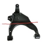
But, the thought would be to simply cut the LCA parallel to the axis (as shown), and re-weld it with the outer portion offset forward by perhaps .5 to 0.75". Obviously, any gaps would be simply patched.

Things I don't know:

1) If the actual material of the LCA is work- or heat- hardened in any way such that welding would degrade strength or toughness. If so, additional plating could be added to regain that strength. Honestly, though, this would be a perfect time to at least weld a plate over the open portion, much in the way LCA skids are done, which would certainly also increase strength.

2) Any geometrical limits that would not allow this; specifically, I don't know if you'd run into issues with the steering tie rods not being able to reach the extra several mm required.

Thoughts?
 

Attachments

  • 20180919_084047.jpg
    20180919_084047.jpg
    34.2 KB · Views: 391
Register to hide this ad
So, I have been pondering on this for a while, partially to resolve the inevitable alignment challenges at higher lifts, and partially to pursue larger tires with less significant firewall tubbing.

But, the thought would be to simply cut the LCA parallel to the axis (as shown), and re-weld it with the outer portion offset forward by perhaps .5 to 0.75". Obviously, any gaps would be simply patched.

Things I don't know:

1) If the actual material of the LCA is work- or heat- hardened in any way such that welding would degrade strength or toughness. If so, additional plating could be added to regain that strength. Honestly, though, this would be a perfect time to at least weld a plate over the open portion, much in the way LCA skids are done, which would certainly also increase strength.

2) Any geometrical limits that would not allow this; specifically, I don't know if you'd run into issues with the steering tie rods not being able to reach the extra several mm required.

Thoughts?

[MENTION=116470]Tyler James Inc[/MENTION]
 
Not crazy at all; I've been talking about this for a year or so now.
I don't think chopping/welding the arm in the center would be the best approach, but that's just my opinion.
I think if you cut/extended the rear leg of the arm, it would be a lot less work, and would be less integrity-compromising to the arm.
 
LCA's

I think the best improvement to the LCA's would be a redesign/modification where they would be like a swingarm on a motorcycle; meaning they would be free to move up and down with suspension movement that is free of friction of rubber bushing twist resistance. It would still be the alignment mechanism but sealed each end and free to move up and down.
Am I off base here?
I realize this would not address your specific lift issue. Just another thought on LCA's.
 
Not crazy at all; I've been talking about this for a year or so now.
I don't think chopping/welding the arm in the center would be the best approach, but that's just my opinion.
I think if you cut/extended the rear leg of the arm, it would be a lot less work, and would be less integrity-compromising to the arm.

Thanks! Yeah, my first thought was to to extend the rear arm like you said!

However, the forward leg would still need to be modified to account for the new geometry. In doing so, it also makes sense to shorten it by the same amount (or slightly more) so that the required CV length doesnt change. My main concern with this method was simply the accuracy with which I could make these modufications, since I would be changing both the lengths and mounting angles of two separate legs on each arm.

Conversely, making a single cut across the body of the LCA should be easier to do with a decent amount of accuracy, and re-welding it along the existing plane again reduces the challenges of accurate reassembly.
 
From what little I've read control arms and stamped/welded steel components like this are all mild carbon steel. Easy to form & weld, tough but not really hard or ultra strong. So the material should lend itself well to hacking and welding.
 
From what little I've read control arms and stamped/welded steel components like this are all mild carbon steel. Easy to form & weld, tough but not really hard or ultra strong. So the material should lend itself well to hacking and welding.

Consider that the geometry of the part may also play a role in it's strength. Not saying that you shouldn't do it, but be careful with how you do it.
 
However, the forward leg would still need to be modified to account for the new geometry. In doing so, it also makes sense to shorten it by the same amount (or slightly more) so that the required CV length doesnt change. My main concern with this method was simply the accuracy with which I could make these modifications

I guess it depends on how much you plan on moving your LBJ location. I only wanted about 1" forward. With the leverage considered, that's like- what- 1/2" extension at the rear leg? Cut off wheel to the front leg- leaving the front edge- to relieve the bushing, weld it back up and you'd be golden. That's definitely not enough to have an impact on your CV length.

To be clear- I wouldn't do this without making a jig to keep the pivot point perfectly lined up.
 
I guess it depends on how much you plan on moving your LBJ location. I only wanted about 1" forward. With the leverage considered, that's like- what- 1/2" extension at the rear leg? Cut off wheel to the front leg- leaving the front edge- to relieve the bushing, weld it back up and you'd be golden. That's definitely not enough to have an impact on your CV length.

To be clear- I wouldn't do this without making a jig to keep the pivot point perfectly lined up.
I suppose that brings me to my 3rd unknown: how much radial play is there in the CV axles? I know there has to be a little because theoretically the factory LCA adjustment bolts could pull the LCA in or out a small amount.

But indeed, if the CV can handle being potentially extended another 1/4", then indeed that would work without having to shorten the front leg.

Also yeah, I think 1" forward would be plenty. Right now I only get very minor rubbing on my 33s at the back of the wheel well while flexing, so an inch forward would theoretically clear 35s without any major modifications (i.e. tubbing) beyond maybe some elbow grease with a BFH.

Would 1" forward cause any issues with the tie rods?

On a separate note, does anyone know the thickness of the actual LCA steel?
 
Not crazy. In fact it's refreshing to see the consideration for simple fixes rather than spending big money on aftermarket.

I know a forum guy that did your way on a 61 Pontiac wagon and he uses that as a tow vehicle. It worked well for him. So I did the same exact mod on my 61 arms using 1/4" plate for surface in between for the 'shift'. But I hated it. It just did not seem right. So instead, I cut out the mounting ear from frame and rotated it. That felt A LOT better.

But on our trucks, relocate the mounting point is not so easy. But here's a thought that may be much better than what you propose. I believe if you box in the replacement bracing, it will be every bit as strong as original. For the fulcrum side, don't cut all the way through, just a cut until you can bend an angle. If you do it this way, it is extremely easy to match your two sides by measuring the gap on the through-cut side.

You can see how goofy it was when I attempted it on my Pontiac. I did not use them, however that forum guy has been towing on the same exact mod for years. Bah, I can't find the picture, but I promise you it looks whacky... just give it an episiotomy like the below picture.

Edited to add: I'm not sure if my diagram shows it in correct direction, but you get the idea.

2lk8u3q.jpg
 
Last edited:
Here's pic from the Pontiac forum. Very bizarre looking but it works. He did on the upper. And actually, I think it's worth considering if upper or lower is under more stresses, I can't recall, but IIRC one of them is under a lot more stress than the other. My intuition is saying that bottom control arm is under more stress because the sprung weight is supported there. I'd do the mod to the upper CA, not the lower.
 

Attachments

  • tmpphp5ip9Df.jpg
    tmpphp5ip9Df.jpg
    50.3 KB · Views: 295
I suppose that brings me to my 3rd unknown: how much radial play is there in the CV axles? I know there has to be a little because theoretically the factory LCA adjustment bolts could pull the LCA in or out a small amount.

But indeed, if the CV can handle being potentially extended another 1/4", then indeed that would work without having to shorten the front leg.

Also yeah, I think 1" forward would be plenty. Right now I only get very minor rubbing on my 33s at the back of the wheel well while flexing, so an inch forward would theoretically clear 35s without any major modifications (i.e. tubbing) beyond maybe some elbow grease with a BFH.

Would 1" forward cause any issues with the tie rods?

On a separate note, does anyone know the thickness of the actual LCA steel?

1" at the lower arm won't be that much at the center of the tire, unless you moved the upper arm too.

More importantly if you moved the lower arm forward 1", the Caster angle would be severely impacted, my best guess is at least 7 or 8 degrees more positive. Could be ok, but I wouldn't run that much caster on daily driver.
 
...More importantly if you moved the lower arm forward 1", the Caster angle would be severely impacted, my best guess is at least 7 or 8 degrees more positive...

Can calculate if you know the distance between UBJ & LBJ. I think I remember about 19"?

1" change swung from 19" would be 3.0°. I suspect that would be in the wheelhouse and the camber bolts would end up somewhere in the middle of the adjustment range.
 
Can calculate if you know the distance between UBJ & LBJ. I think I remember about 19"?

1" change swung from 19" would be 3.0°. I suspect that would be in the wheelhouse and the camber bolts would end up somewhere in the middle of the adjustment range.

My tired old brain was using tire diameter, but yes the pivot would be the upper ball joint and the swing would measure at the lower. I could actually simulate this on an aligner if I had less than 602,579 projects going already.
 
My tired old brain was using tire diameter, but yes the pivot would be the upper ball joint and the swing would measure at the lower. I could actually simulate this on an aligner if I had less than 602,579 projects going already.
Here in the AF tgat number would be estimated as 696,969 projects, sir. ;)

Thanks everyone for the input!

Also, keep in mind that while a 1" forward bias adds 3 degrees of caster, a vehicle lifted 3" without adjustable UCAs likely doesnt have the adjustability range to even keep both camber and caster in spec. So, that 1" forward bias should actually result in a much more standard alignment, if perhaps with only a slightly heavier steering feel.
 
Last edited:
Can calculate if you know the distance between UBJ & LBJ. I think I remember about 19"?

1" change swung from 19" would be 3.0°. I suspect that would be in the wheelhouse and the camber bolts would end up somewhere in the middle of the adjustment range.

My tired old brain was using tire diameter, but yes the pivot would be the upper ball joint and the swing would measure at the lower. I could actually simulate this on an aligner if I had less than 602,579 projects going already.
 

Members online

Forum statistics

Threads
278,316
Messages
3,554,110
Members
248,016
Latest member
Advally Service

Trending content

Back
Top