CSix Build Thread

So, since it was going to be rainy in Denver and the wife wanted to go camping, thought we'd go camping in Steamboat Springs Colorado. Now, we decided to camp at the Fairfield Inn... Close enough.

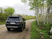
From Denver to Steamboat we were in a white out (snow) over the Eisenhower Tunnel out to Rabbit Ears Pass. Rain in Steamboat. We decide to explore some and go to Buffalo Pass... Closed. We drive several county roads in search of lakes for fishing. Every dirt road was washboard, mud and pot holed... great test for the new suspension. I will say 6112's and 5160's handled the washboards, holes and trenches real well. A lot better than my old CJ...

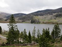
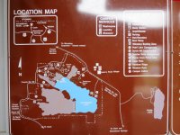
We actually found a relatively new state park lake that is all Gold Medal water. Pearl lake is really a hidden jewel with all new camp sites and even some yurts. We will be back.

Oh, visit the post-office-general-store in Clark Colorado for an amazing breakfast burrito and burgers... (really!)

Also, we averaged 22 MPG on this trip!


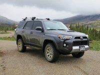
Buffalo Pass before the Gate.
IMG_3354.jpg

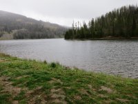
Pearl Lake
IMG_3361.JPG

IMG_3358.JPG

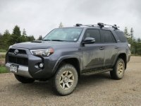
I'm liking the suspension and its stance more and more.
IMG_3362.JPG

IMG_3363.JPG


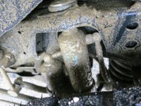
Bilstein 5160's covered in mud. I re-routed the braided line to the remotes behind the shock away from the tire. I like this set-up a lot better. The lines are not touching anything and well protected.
IMG_3365.JPG

Another pic of Pearl Lake
IMG_3370.JPG
 

Attachments

  • IMG_3354.jpg
    IMG_3354.jpg
    63.1 KB · Views: 1,496
  • IMG_3361.JPG
    IMG_3361.JPG
    115.5 KB · Views: 1,441
  • IMG_3358.JPG
    IMG_3358.JPG
    118.5 KB · Views: 1,450
  • IMG_3362.JPG
    IMG_3362.JPG
    106.1 KB · Views: 1,479
  • IMG_3363.JPG
    IMG_3363.JPG
    108.6 KB · Views: 1,776
  • IMG_3365.JPG
    IMG_3365.JPG
    123.3 KB · Views: 1,468
  • IMG_3370.JPG
    IMG_3370.JPG
    122.4 KB · Views: 1,440
Hey CSix...Love the build and your page's dedication to mtn biking. I'll weigh in on your rack convo...I just sold my T2 and purchased a Kuat NV for my Trek Fuel EX...love it! Much more solid rack with better locking mechanisms. I did the roof top bike trays in the interim and although it can be a bit of hassle opening up the tail gate with the hitch mount, it is faster and easier to load/unload. Nuff said 'bout that.

On to your lift!

I'm looking to achieve close if not the same kind of lift you've installed. I was originally set on the TRD Pro suspensiondue to the brand and compatibility with the 4R, but I'm a little nervous about the "clunk" issue and I don't believe it provides much of a gain in stance/lift - about 1" from what I've read.

I was hoping to ask a few Q's on your 6112/5160 +Icon Coils. Like you, I'm mostly concerned with on-road ride quality but would like have a taller stance/more clearance. I do travel down dirt roads to access fish/mtn bike spots and occasionally off-road for work and so I want the additional capability, plus I really think the 4R should be built taller, but 95% of the time, it'll be driven on the highway. I have a '15 TEP w/KDSS. I love the way the truck rides stock and my only hesitation on adding a lift is losing those ride qualities. I'm not adverse to spending the money for a legitiamte/well built suspension to achieve the best on-road ride quality - meaning If i need to spend more money than a set of 5100's and a daystar spacer in the rear, I will most certainly do that - in my mind, this seems like just a cheap way to lift a truck without having too much regard to ride-quality.

I've come from a 2009 Tacoma TRD Sport and I am really enjoying the nicer ride the '15 4R TEP, but that is about all I have for frame of reference in ride quality.

Given your experience and bold move to go with the 6112/5160 + springs, I'm looking to get a better understanding on what to expect for on-road handling when compared to a stock TEP w/KDSS. If your willing to share...feel free to PM me so I don't muddy your build thread.

Truck looks great...I'm jealous of your bike and I love CO! I wish I owned a 4R in CO...I could justify a lift much more than where I am in NH...however we do get out and play ofter!

Thanks ahead of time!
 
Last edited:
[MENTION=117783]MATTYDIRT[/MENTION]

Thank you for the kind words. I love the Mtn bike but been riding a lot of road lately. There is a road ride called the Triple Bypass, with Team Evergreen, that I ride every year. I've ridden the double triple bypass option the past few years... 125 miles and 12000' for the single... double is times 2... so, we'll be doing our first practice century Saturday. Once the trails dry out (we have had a lot of rain), I'll ride the Tallboy again.

Well, here are some thoughts from driving now for a bit. I like the specs of the TRD Pro suspension. I like the 6112/5160 because it is adjustable and has no clunk. Not trying to sell you on anything... these are just my thoughts... So, here goes...

I'm liking the way the 6112's and 5160 combo is riding better every day. I was just up to Turquoise lake last week near Leadville, Co. I have ridden Rollins Pass till the snow was too deep to continue a few weeks ago and I drove to Steamboat over Memorial Day weekend in a major blizzard over Loveland Pass and Rabbit Ears Pass. Temps all in 20's to 30s... No clunk.

Feels great on and off the road. I do not have KDSS. The ride up to Leadville is 120 miles. The digressive valving really makes high speed travel on bad highway feel great. The increased spring size in the fronts firms the ride a bit and is in no way stiff. It is no race car. But nose dive is greatly reduced. It really just feels good. Now, you can put the 6112/5160s on with KDSS. That could be perfect!

The 2" Icons and the 5160s feel meant for each other. The stock springs are too squishy for the 5160s according to Zeus in that thread below... So, I am glad I went with them. I see a lot of people wanting to "level" their rig, only to be nose up when loaded and off road. That is a choice. I like the factory rake but up 2 inches. The trucks rear likes it too in the off roading we've done so far.

Off road, the suspension really handles washboard, rutted and potholed roads better than any other suspension I've had and that included a Land Rover Disco II and Monster Jeep CJ7 i built for Moab. I like the 60mm size of the 6112s since I will be doing some rock crawling... way more robust than stock or 46mm 5100. The remote reservoir of the 5160s in the rear is probably a bit over kill but I do ride on long washboard roads and the reservoir can only help.

I like the 2" lift with potential to go 2.5 or 3 inches. Not sure I will but... one never knows.

5100's are good and way cheaper. But, they are still smaller and not as robust. 5100s ride better than stock. But, IMHO... the 6112/5160 feels, if I have to quantify, at least twice as good as 5100... again, my opinion.

I purchased from
TotalAutomotivePerformance.net . I talked to Chaz or Mike. They are extremely knowledgeable and good to work with. Ask them about KDSS. They helped me with the spring rates and that's why I went with the 2" Icons. They also have a 6112 thread under their vendor section that has a lot of info.

I think if you stay at or under 2.0" you should be fine with KDSS and 6112/5160s but you probably should confirm with Total Automotive. Over that then you need UCA's and that will impact KDSS. Members 4runher and [MENTION=109458]letzrace[/MENTION] both have KDSS. Check with them or the thread below has several rigs to check. The people on the thread were real cool too.

This thread has a lot of good info.
http://www.toyota-4runner.org/5th-gen-t4rs/183858-when-will-bilstein-6112-released.html

Well, good luck! Let me know what you do.
 
Last edited:
Hey CSix! I've enjoyed your build thread, especially your suspension upgrade to the 6112/5160. I am very much interested in a 2" lift and am getting close to making a decision on which lift to purchase. You've had yours on for about six months now.

After a summer/fall in the Rockies, do you have any final words of advice? I'm most interested in how it has handled the on road and off road paces you've put it through. Has its alignment remained good for daily driving? Any settling? If you were to give this suspension a "grade" for how you use your vehicle what would it be? I use my vehicle on and off road and my needs seem similar to yours. My rig is slightly different as I have the KDSS trail version.

Thanks for creating your build thread and any updates on the suspension you can provide - very helpful!
 
ARB Compressor and Cooper Bussmann Wiring

CSix,

Great build and super helpful. I am doing virtually the exact same install on the ARB compressor and Cooper Bussmann. Can you help clarify the wiring for me?

Where did you connect the pressure switch (Red and Blue tabbed wires off the ARB Valve)? Did you tap off the same switched relay line as the main compressor power line?

Thanks!

Mod #2 ARB Onboard Air Compressor Amazon.com: ARB CKMA12 Air Compressor: Automotive

The ARB Compressor CKMA12 is a small enough unit to mount that can deliver reasonable air pressure to stock sized tires. This compressor will be primarily used for airing up tires, inflating air mattresses, airing off trail dust and air hosing my dog and filling bicycle tires for me and my friends…

Since I have the Fused Relay block installed, the switch is already ready and waiting. I will mount the compressor and run the wires to the fuse block and be done.

The first step is to decide on the mounting location. I chose the passenger side of the engine bay because the location has three M6 holes screaming mount me; it’s in an open location and in the same loc as the one I had on my Jeep.

I figured a slab of steel plate with mount holes I drilled (use paper to trace the hole locations) that match the upper holes on the side of the engine compartment would be strong mount and keep the unit out of the way. I also have a connecting bracket mounted to the top of the wheel well for extra support. I did drill a hole in the fender for the support, and then painted after mounting to keep it water proof.

Ingredients:
ARB CKMA12 Air Compressor
Steel plate I had laying around but you can get from a hardware store
M6 grade 8 bolts for the side of the engine bay. About an 1.5 inches long.
Large Fender Washers – I use these for extra support
Large thin rubber Fender Washers to protect underneath mount
Spring lock washers
Black High Temp spray paint
M8 20 bolt (for the fender well)
Support metal 1.5” bolted to bottom of bracket to fender well

Fabrication of the mounting plate
View attachment 150051

Mounting Plate and ARB Bracket. The three holes on the top match the three M6 holes in the side of the engine bay. The three on the bottom were drilled because I’d definitely use one, just did not know where I wanted the bottom support to go at the time. The gold plate is the stiffening plat that came with the ARB Compressor. Yes, the compressor needs all four of those holes.
View attachment 150052

Test fit. I ended up rotating the actual mount 90 degrees.
View attachment 150053

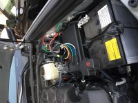
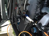
Once mounted, I cannibalized the ARB power and ground wires, because they have a connector that fits the ARB. I used the red wire that came with the ARB to connect to the accessory wire of my power block. I used the Black ground wire from the original ARB harness too. From the Power Box install, I measured the accessory power wire to the compressor, the pressure sensor wires, strung them from the mounting location to the relay box, wrapped in split loom wire cover, taped where appropriate and zip tied along the rear of the fire wall. Then, I connected the ground at the compressor location on an official ground site (one next to the air filter box). Note, a pressure sensor is connected in line to the compressor switch to turn it on and off at a range of 70-100 psi. This can be changed later too if I add an air tank. I added an air manifold and have a stainless ¼ NPT from the compressor to the manifold with the pressure sensor and an NPT quick disconnect. I also had a pressure relief valve… but, it leaked… so, I blocked up the empty locations on the manifold for later. One of the empty locations will route air back to the rear of the rig. I’ll be doing that later.

Compressor mounted on passenger side before being connected and powered
View attachment 150054

Compressor mounted and powered. Stainless Air hose connected to a Vivair Manifold. Pressure sensor and ARB NPT connector are on the manifold.
View attachment 150055
 
Hey CSix! I've enjoyed your build thread, especially your suspension upgrade to the 6112/5160. I am very much interested in a 2" lift and am getting close to making a decision on which lift to purchase. You've had yours on for about six months now.

After a summer/fall in the Rockies, do you have any final words of advice? I'm most interested in how it has handled the on road and off road paces you've put it through. Has its alignment remained good for daily driving? Any settling? If you were to give this suspension a "grade" for how you use your vehicle what would it be? I use my vehicle on and off road and my needs seem similar to yours. My rig is slightly different as I have the KDSS trail version.

Thanks for creating your build thread and any updates on the suspension you can provide - very helpful!


Hey SierraMare... Sorry for a late response as I was out of the country then got real busy... but I digress...

I really like the suspension/tire combo. I feel this is how a 4Runner should be stock. I have driven a lot of off road from forest roads around Steamboat, and Jones Pass, Loch Lomond, Mosquito Pass, Tin Cup, roads around Leadville, Montezuma and Hagerman Pass. Handles washboards extremely well. Handles rock crawling extremely well. Daily driving has been rock solid and a real minimal nose dive. The feel is much more refined and hits are much better than stock at high speed = great highway drive. My wife really comments how much better the ride is... I cannot speak to the KDSS but I feel my suspension was a great upgrade.

Good luck!
 
CSix,

Great build and super helpful. I am doing virtually the exact same install on the ARB compressor and Cooper Bussmann. Can you help clarify the wiring for me?

Where did you connect the pressure switch (Red and Blue tabbed wires off the ARB Valve)? Did you tap off the same switched relay line as the main compressor power line?

Thanks!

Yo Wild_turkey!

I have the pressure switch in line from the power distribution box relay to the switch in the dash. Reason: not much power needed and I do not want it in the main power line. Also, power is only on when the button is pressed.

See the visio diagram...
http://www.toyota-4runner.org/5th-gen-t4rs/192041-csix-build-thread.html

Thanks!
 
ARB Compressor and Cooper Bussmann Wiring

CSix,

Thanks! I see it in the Visio diagram now that I zoomed in.

I ended up leaving most of the ARB wiring intact and connected both the main compressor power and the pressure switch relay to the same Bussmann accessory wire, leaving both the ARB 40A fuse and relay inline. It seems to work fine and gives me some extra protection. Hopefully it doesn't come back to bite me having to replace multiple fuses and relays!


Yo Wild_turkey!

I have the pressure switch in line from the power distribution box relay to the switch in the dash. Reason: not much power needed and I do not want it in the main power line. Also, power is only on when the button is pressed.

See the visio diagram...
http://www.toyota-4runner.org/5th-gen-t4rs/192041-csix-build-thread.html

Thanks!
 

Attachments

  • IMG_1650.jpg
    IMG_1650.jpg
    141.3 KB · Views: 1,030
  • IMG_1649.jpg
    IMG_1649.jpg
    134.3 KB · Views: 1,110
  • IMG_1648.jpg
    IMG_1648.jpg
    132.5 KB · Views: 1,147
Mod #1 Cooper Bussman power distribution box with 5 fused 35amp relays and 5 fused non-relay
Universal Relay Fuse Auxiliary Distribution BOX Block Jeep Cooper Bussmann | eBay

Disclaimer – This is what I did to the best of my memory to fabricate and mount a wiring harness and power distribution box. No warranties will be given or implied. Actual results may vary. I have seen several rather good write ups on installing a Power Distribution Box so I thought I’d add my own distinctiveness to the collective… Also, there is a lot of work involved. Enjoy…

A power distribution system is really just an additional fuse and relay box used to power your auxiliary devices. Reasons to have one: additional centralized power not patched into existing fuses boxes; organization of relays so you don’t have them and their wires all over the engine bay, and once it’s set up you can add auxiliary devices fairly easy.

This power distribution box has 5 fused 35 amp relays and 5 15 amp fused power sources for a total of 10 separate power sources. Wiring looms that come from the accessory may be cannibalized or may not even be necessary. In the end, the power box built will be connected with switches so when I add an accessory, I mount it and run the wire to the accessory line, ground, add a fuse to the power box where needed and the switch/accessory works.

The first step is to lay out a design of what you want to do. In my case, I am building the power distribution box to handle an air compressor, rear lights, spot lights, driving lights and an open relay for future use (Front Locker). I will also be using some of the 5 always on fused locations. Here is a Visio of my plan.

Visio diagram plan
View attachment 150041

Next step is to get what you need to put together:
Switches from Air On Board
Wire – 16g for power box to switches with selected colors to match the wires from the power block
Bullet connectors in 16-22 (you can never have too many)
Butt splices 12-14
Crimping tool! Yes, save yourself the hassle right now and just get one
Heat shrink tubing and mini torch
Soldering iron, electrical solder
Electrical tape, black and white (to write on)
Zip ties, lots of them in several sizes. Small sizes help build the wiring loom
Diodes – 1n504 3amp for Headlight and aux power sources (may already be in a wiring loom)
T-Taps or Scotch wire connectors
Split wire covering for wires the engine bay
High Temp black paint
Bussmann BP/HHH ATM Add-A-Fuse

Then, plan where you want to mount the new Relay box while laying out what you want in a wiring harness. This will determine the wire lengths, ground locations, etc. I chose a location next to the other fuse boxes because they are close to the battery. The location selected uses existing bolt holes on the driver’s side.

Fabricate a mounting Bracket: This took a bit of time trying to pick the right spot and fabricate the bracket. I used 1.5” support metal purchased at Home Depot cut, cleaned up, bolted and painted. I used existing M8 1.25 thread holes on the driver’s side engine compartment to mount fabricated L brackets with another strip bolted together and mounted close to the battery. I also used another piece of metal bolted to the underside of the bracket bolted to an existing M8 hole on the fender, for extra support.

Power Box Mounting Bracket, sanded – Before paint
View attachment 150043

Power Box Mounting Bracket, sanded – After paint:
View attachment 150044

Painted and attached
View attachment 150045


Build the loom to match your switches and power requirements per your diagram. Mine looks like the Medusa’s spawn with wires for 5 switches. All switches from AOB have four wires: Power from relay, Power from a 12v source where the power can be power from a switched 12V (for accessories like a compressor) or 12v source (from headlight high beams) depending on the switches use, power for dash lights and Ground. I have a diode on the power from the aux switched and headlight sources to protect the switch and prevent power flowing back. Watch the way you mount these. The Gray bar on the diode is on the switch side.

Measure the lengths of wire needed from the switch locations to the fire wall then to the switch block. Measure and measure again then give yourself another six inches.

I built the wiring loom so I could have all the connections to the switches inside the cab and run just one end to the power distribution box through the fire wall. I did this to route the wire loom through the firewall easier. I also labeled all the wires by the number on the fuse block and the intended use. I used white electrical tape and a sharpie. The wire color purchased also matched the wire color of the wires from the switch block. Color coordinated and fashionable!

Once the wire harness was completed, I also used a multi meter on an ohm setting to test to make sure all wires are routed correctly. I then wrapped the loom in black electrical tape and taped a folded piece of spare wire through to a point and the end of the loom. This end will actually contains a wire for each switch that connects to the relay, the ground and the power wire for the headlight activation. I’ll use the length of wire taped at the end to drag the wire loom through the firewall. Note: the thin spare folded and taped wire’s sole purpose is to pull the wire harness through the firewall grommet.

Compressor, Power Distribution Box, wire loom and assorted stuff… The wire harness has all black ground wires soldered together and only 1 ground passing to the fire wall. There are 5 switch accessory wires and a wire that powers the switch with 12v from high beams for the driving and spot lights…
View attachment 150046


After building the internal loom, connect all bullet connectors to all the wire ends of the loom as well as the matching pair on the four wires to each switch. Do not put connectors on the side needing to pass through the firewall. (doh) This will be done later.

The 2015 4Runner Trail Premium has a spot in the firewall grommet that you can pass the wire loom through. It is a round nipple that can be snipped off leaving a rubber tunnel big enough for 8 16g wires to pass through. I pushed a coat hanger through first then the wire I taped to the wiring loom end and passed the wire passed right through. I then pulled that end of the wire through the firewall. My measurements were correct and the wires met at the relay box with enough to spare.

If you did it right, the color wires of the loom match the color of the wires to the switches on the relay box. I then added the bullet connectors and connected the switch wires to same color wires of the relay box. Add bullet connectors or butt splices to both ends, cover the wires with a wire covering for the engine compartment and zip tie it accordingly.

This note is in the compressor install… I only have the compressor installed right now so, I measured the accessory wire to the compressor, the pressure sensor wires, strung them from the mounting location to the relay box, wrapped in split loom wire cover, taped where appropriate and zip tied along the rear of the fire wall. Note: a pressure sensor is connected in-line to the compressor switch wire to turn it on and off at a range of 70-100 psi. This can be changed later too.

So double check connectors on the relay block will fit into the connectors on the wiring harness in the engine bay, check the connectors on the wiring harness that will connect to the switches from AOB. Then, check the connectors on the switches. Now’s the time to see if they are crimped well enough, trust me on this.

Since I labeled all the wires that match the switches and already added bullet connectors, the next step is rather easy. Connect them all up. The switch blanks in the dash are accessible by pulling down on the lower dash panel, next to the steering wheel. It pops out with a good pull. (Thanks Antman) The blanks have a spot in the top and bottom that can be pressed and they really just pop out. The blank next to the dimmer switch is a bit more challenging but a very small screw driver stuck in the bottom of the switch blank from the back pushes the mount clip and that too pops right out.

I have two aux devices that I want to run anytime; I used a Bussmann BP/HHH ATM Add-A-Fuse
that really just plugs into an open slot of the inside fuse box in the white box on the driver side box just under the left side of the dash, or replaces one of the fuses. Then, I connected bullet connectors to each side of the wire and plugged it in. I have this on un-switched power right now but will find a switched power fuse slot.

Pop out the old blanks, place the switch, with the connectors attached, through the hole… do not fully clip back in yet. Check wire length and see if your measurements worked. A second set of hands is really helpful in holding open the box, keeping a light on the work space and feeding you bites of slow roasted turkey sandwich and coffee.

Connect up the power… Measure the red and black wires from the power box to the battery. The red power wire is 8 gauge and the black ground is 10. Cut as needed and add a circle connector with a crimping tool. I Connected the power box ground, and the ground from the wire loom to the battery ground point on the side of the engine compartment next to the battery. Then I connected the heavy 8g wire to the battery. (no sparks… a good sign!)

Right now in my build, there are 3 fused relays and 5 fused power sources not used, but they will be. I pulled out the fuses then wrapped the aux wires in tape and split cover. When needed, I’ll pull out the appropriate “accessory” wire, add a fuse, connect the wire to the accessory and watch it work.

At this point I tested the switches and that I had power coming out of the accessory wire on the relay, with the multi meter. Everything works. Then I plugged everything back in, popped in the switches and buttoned all up.

What’s left? In my wiring harness, I have the blue wires connected as dimmer power so I just need to connect that wire to a wire coming from an existing dash illumination wire. I have read that wire is a green on any switch. I still need to connect the blue wire with a scotch or red T-Tap for the dash illumination. But, it’s tested with un-switched power. Next week, I will to tap into the high beams, for the driving lights but I decided to take Saker’s advice and use a 9005 extension that I’ll tap into. (just ordered from Amazon.

Dash opened up showing the backs of two AOB switches (green)
View attachment 150048

Switches installed - AOB switches fit pretty dang good.
View attachment 150047

View attachment 150049

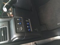
Note my switch locations. The Air compressor is a long way away and I will not accidently press it. The others, well, I just filled in the empty blank holes. The stock switches are keyed and only fit in one location. I can grind off the keying and mount them anywhere I want but that will be saved for a later date.

Almost done....



What wires did you end up tapping into for your power and ground for the switches?
 
Great write up! I just installed 6112's in the front and 5160's in the rear. I'm on the 4th clip in the front and was looking for a rear spring to match the other changes. I've been on the fence but read your write up and will pick up a set of Icons.
Thanks again for a clean write up and explanation of the modifications you've made. Cheers!


Sent from my iPhone using Tapatalk
 
When you installed this suspension setup, did you add anything for the swaybars or diff drop? I have checked and didn't see anything... just wanted to make sure!

This looks perfect for our 5th gen coming soon!

Thanks CSix!

Mod#5 – Bilstein 6112/5160 Suspension aka TRD Pro Suspension

Ok, so I knew I was getting a 4Runner and I knew I was going to upgrade the suspension. But… upgrade to what. I liked the specs of the TRD Pro suspension even before Bilstein rolled out the 6112/5160 suspension combo. I considered other suspensions, the usual suspects… and researched from the suspension thread, builds and general comments. I ended up with the 6112/5160 combination for what I wanted… overall 2” lift, ability to go larger, well built for off road great on road manners and adjustable.

My wife would only get the 4R with a locking rear diff (She’s wheeled in my CJ) and I wanted the Trail edition Premium but the TRD Pro was coming out… Well, I have to have my sunroof… sorry TRD Pro… Let the build begin. In the end, I’m glad I went this route because I have the truck I want with the lift I want and all sorts of potential.

View attachment 156621

I’ve replaced several suspensions on Jeeps, thought I’d do this one too. But, I just got all the parts in and ouch… I have a cold… and then there’s Mothers day coming up with more rain in the forecast… and I wanted to put it in as soon as I could. The dealer can do it with their best mechanic…
Oh wow, my man card is in jeopardy… Wife says, “but look at all your mods… and you’ve already done stuff like this…” So, man card still intact. I paid $$$.

Now, I actually like my 4Runner stance especially when I have a dog and a bunch of gear riding in the St John’s area. Many people like the level look. I like it too. But, I really just want the stock look but 2” higher. I was a bit apprehensive going 2” all the way around because no one had done it yet with the 6112’s/5160s with springs… documented… time to break new ground.

There are many combinations of equipment, vehicle options, and suspensions that will affect the height of the lift as well as the drivability. Every application really is different. The cost of failure is high. You really don’t want to rework or pay twice, etc. Time to do my homework.

The 6112's installed in the front at the third C clip setting look to have a ~2" lift on a 2015 T4R Trail. There are 5 settings. In inches the actual values noted: 1=0, 2=.95, 3=2.0, 4=2.5 and 5~3.0. This differs greatly from the Bilstein published specs. Several members forged ahead and found this information. I have only seen installs of 2nd, 3rd and 4th clip settings. No #1 or 5 as of yet on a 4x4. So the numbers for those here are estimates. So, at the third setting, I can still increase the setting if I feel the need or add a winch bumper.

The rear 5160's are a remote reservoir shock and are not supposed to add any height. Reading through the posts, there may be something to the 5160’s adding half an inch or so. Then, I took all builds thusfar side to side, and noticed many people used the Sway away 1.5 spring. I did some checking and calling and found the SAW springs indeed give 1.5 inches on Runners with 3rd row seats. To me, that means, maybe 2” on non third row vehicles? A discussion with Bilstein seems to confirm.

I wanted a spring that worked with the 5160s and was not too squishy or hard, noting [MENTION=77958]Zeusmotorworks[/MENTION] comments on stock springs (thanks Zeus). I talked with Bilstein and Total Automotive on the spring rates and what’ll work best with the 5160. I decided on the Icon 2” spring for my application. Now, it seems like all springs are made by Eibach… Guess Icon will have to do.

Plan: First, Install the 6112’s up front at the 3rd clip setting for ~2” lift. Then, install rear springs (not spacers) for a 2” increase too.

I had the local Toyota dealership perform the install. (yes, man card in jeopardy). But, the tire guy and parts guy are cool and service was great with another issue after a major hailstorm… I’m told the mechanic had a bugger of a time with the increased size of the rear coils and I was glad I was not on my back with a cold, under a cold wet 4Runner applying brute force and ignorance principles to stubborn rear coil springs… Job looks real good. I will rearrange the remote reservoirs but, the underside is muddy and wet and the weather ain’t getting better until next week or so!

Tires are Nitto Terra Grappler G2's. I'd say I came right in at 2".

Actuals: Measured after 50 or so miles up Highgrade road to Conifer and back.

Before After Lift
L Front 34.5 36.5 2.0"
L Rear 37.0 39.0* 2.0"
R Front 35.0 36.5 2.0"
R Rear 36.75 39.0* 2.0"

(Actually, 39 1/8" but i rounded...)

View attachment 156622

View attachment 156623

Notes:
I'm amazed that the side to side "lean" disappeared after the lift. [MENTION=103267]Saker[/MENTION] noted similar equality between the sides.
No lift noted from the 5160s, only the springs. My dog is in the back and it came out 2 inches exactly. Now, he needs to jump a tad bit higher...
The mechanic said the Alignment came in perfect. (I do not have the sheet)

We took it for a drive up High Grade Road. Yes, it's pouring out... a real good test. Driving has a much improved feel. Tracking, bumps are indeed handled better (the driver alert bumps kinda melt away). IMHO, this is how the 4Runner should be stock. Yeah, suspensions are subjective and definitely won’t say this is the best thing since sliced bread sprinkled with unicorn dust but, really... I do like.

View attachment 156626

View attachment 156625
 
Great Job!

Definitely subscribed to your build thread! Great job!

...now if I can only convince my wife to let me do 6112/5160 setup... (after we finish building our new house)

Cheers!
 
When you installed your 6112's for 2" of lift, you said you set it to the 3rd clip. I'm also trying to achieve the same amount of lift and I'm going to throw the 5100's in the back with the ICON 2" coils.

Looking at the instructions for the 6112's here
http://cart.bilsteinus.com/pdfs/E4-WM5-Y506A00_1.pdf

Does that mean you set the recommended 1.55" setup
Passenger @ 4
Driver @ 3

or the 1.14" setup
Passenger @ 3
Driver @ 2

Thanks for the help
 
When you installed this suspension setup, did you add anything for the swaybars or diff drop?

I'm about to do the 6112/5160 suspension upgrade to my SR5. I have the same question regarding whether or not the front sway bar relocation kit is needed. Also wondering if rear bump stop spacers are needed (planning a 2" lift all around). According to Bilstein customer service the answer is 'no' for both. I've received different answers from local shops. It would be nice to confirm with someone who's done this setup.

Regarding the diff drop... I'm planning to skip it initially and evaluate the need for it once the lift height is dialed in. I've read varying opinions on whether or not it's needed and some opinions suggesting it can be harmful to the diff. Customer rep at Toytec said I can get away without it with a 2" lift but he hasn't heard of any problems from people who have installed them.
 

Members online

No members online now.

Forum statistics

Threads
278,306
Messages
3,554,045
Members
248,016
Latest member
Advally Service

Trending content

Back
Top