DIY: 12volt socket/outlet in your door panels

gshadow325

New member
EDIT: I did this with inline fuses on the power line. I used a 7.5amp fuse. I also soldered the wires in the door. I only showed you guys the idea and how to execute it. Sorry for not clarifying what proper procedures you need to do. Since this mod was a spur of the moment idea, i did not shop around for the outlets. Just grabbed the nicest ones available to me at the time. Ebay and amazon have some real nice ones that have covers, and wire with fuses in the set.

Good luck and have fun doing it.

Repost from my build thread....please read thru entire thread before attempting this. i wrote this not knowing what you skill level may be. there is some good contributions, suggestions and tweaks to this mod.

Yet another DIY from me lol!

I hated the fact that this car only has one 12volt outlet in the passenger area. When you out with one wife and two kids and each of them has a device that needs to be charged one just isnt enough!

was i going to get one of these things?
Victor_39061-8_12_Volt_Triple_Socket_Splitter_and_Adapter.jpg

or this
12v-power-splitter.jpg


and have my rig look like this?
2942690806_9a583a26b0_z_rect540.jpg


I'm a pro, not a best buy/circus city geek squad flunkie

NO WAY!!

So here it is the recipe and receipt!
three casca cig lighter well from your local auto parts store, here in philly its called Pepboys..manny moe and jack


in that top picture in the center is the tool that you need to get. home depot would sell a thing to drill holes just go find the right one. that tool above is a tool i have to drill rear parking sensor holes

Bought three one for each passenger
So started with right rear door.

here are the wires needed for power and ground
green is ground and white is switched 12 volt.

BTW- YOU CAN USE THESE SAME WIRES FOR YOUR POCKET AMBIENT LIGHTING!!! like in the picture below


finished

 
Last edited:
Register to hide this ad
passenger front door

before


12 socket drilled in to door panel


Front view
did the front door a little different since the pockets and lower and longer


front door wires to tag into, brown is 12 volts and red is ground


finished and working

 
Last edited:
driver rear door

Wireing for driver rear door. white 12 volts, green ground


Finished product


you get the idea....i am so happy i thought of this and wanted to share it with my T4R buddies...actually dont have any yet LOL.

this MOD will stop my kids from fighting in the back seat over the charger.
this MOD will stop my wife from taking the charger from me!!

One happy family!! :D
 
Last edited:
Very cool. thanks for sharing and honestly I wouldn't mind another on driver door since I cant stand the one on the center console.. Great job.
 
That's very cool, I like that a lot. At first I was thinking you were putting several in your door panel for some reason and it seemed like a waste but I may have to steal this idea, at least for the rear doors.

I have flush mount dual USB outlet on my dash in addition to the OEM one in the center console and a second I installed in the console so I'm covered up front... but I'm sure I'll need more once the word family starts getting thrown around...
 
That's very cool, I like that a lot. At first I was thinking you were putting several in your door panel for some reason and it seemed like a waste but I may have to steal this idea, at least for the rear doors.

I have flush mount dual USB outlet on my dash in addition to the OEM one in the center console and a second I installed in the console so I'm covered up front... but I'm sure I'll need more once the word family starts getting thrown around...

Oh god not the F word. that means the W word is coming ....Your life....is officially over hahaha
 
Great job... I have a question. For the socket, which pin is ground and which one is power (12 volt)?
 
Couple issues you will want to address to make your mod safe, effective, and save money on fuses.

As RiceandPho said you need to run a separate circuit for each 12v socket. You're loading up what appears to either be the window or door circuits which is not good. Lets say you have all those sockets loaded up and charging, someone unlocks the door or rolls a window you're going to blow a fuse, those circuits aren't really designed for ACC additions like that.

There are a few ways you can do this, by running separate circuits for each socket. Or you could tap into the lighting circuit for the door lights, but this will load up that circuit and pose the same issue. You can use spare slots in the fuseblock to tap off of instead of running a bunch of fuse holders and such.

The other issue I see that is also potentially problematic is that you did not properly splice your wires. You have the right idea, but you need to either solder the joints then cover them in heat shrink tubing or electrical tape. The way you have it set up can cause excessive resistance, loss of connection, arcing against panels or from distance created by improper connection method, ect. Another option is to use add-on connectors that a lot of alarm systems come with (they're like a double wide buttconnector looking thing.)

Your idea is a good mod, it just needs some refinement, great work otherwise.
 
Great job... I have a question. For the socket, which pin is ground and which one is power (12 volt)?
Outer caseing of the socket is ground and center pin is positive.


BlackWorksInc, First off I respect your ASE certification badge in your signature. So i take i also take no offense in your response. they are all valid concerns and i am glad you brought it up. i made the mistake to assume everyone that would tackle a project like this has some sort of knowledge on what they are doing. Just like when i asked you about why you didnt replace the cam seals when you did a timing belt writeup on a V8. :) Your response makes for a good discussion so others can learn from what we know.

FYI: I hold a MECP Advanced Certification. there are only ~300 masters in the country!

Couple of good points you brought up. I will address them in bold

Couple issues you will want to address to make your mod safe, effective, and save money on fuses.
MOD is 1005 safe
As RiceandPho said you need to run a separate circuit for each 12v socket.
No I do NOT, OEM window #56 has a 30amp fuse on it.
You're loading up what appears to either be the window or door circuits which is not good. Lets say you have all those sockets loaded up and charging, someone unlocks the door or rolls a window you're going to blow a fuse, those circuits aren't really designed for ACC additions like that.
As with any MOD. You can run into scenarios like you mentioned. Possibilities are endless. My intentions are NOT to run a power inverter on each socket but to charge devices like ipods and cell phones that draw max 2amps. OEM window motors draw average 5 amps. So 4 doors x 5 amps, plus 3 sockets at 2amps = total 26amps. as stated above the OEM fuse is 30amps. so i am good there.
There are a few ways you can do this, by running separate circuits for each socket. Or you could tap into the lighting circuit for the door lights, but this will load up that circuit and pose the same issue.
doors/dome lighting is only rated at 10amps. adding to that circuit is a no no. plus door circuit is constant power.
You can use spare slots in the fuseblock to tap off of instead of running a bunch of fuse holders and such.
thats very very very DIY/best buy/circus city / geek squad stuff. there are no fuse taps in my shop just like you dont use husky tools from home depot in your tool box. I would expect you to have SNap-on at least MAC tools. I have three Snap -On spring loaded wire cutters in my tool box, and yes my roll away at home is snap-on and so is the one at work.

The other issue I see that is also potentially problematic is that you did not properly splice your wires.
what you see and what i do are two totally different things. I am not here to school people on how they want to connect their wires. my pictures are on what wires to connect to. I use a 1lb spool of solder about one a month. 60% tin and 40% lead with flux in the core for a strong, long lasting bond.
You have the right idea, but you need to either solder the joints then cover them in heat shrink tubing or electrical tape.
Answered above, I used solder 60% tin and 40% lead with flux in the core for a strong, long lasting bond. I use 3M Super 33, best stuff you can buy for 12volt use.

The way you have it set up can cause excessive resistance, loss of connection, arcing against panels or from distance created by improper connection method, ect.
You are right, that sound like the ASE masters certification talking :) BUT thats not the finished product pictures like i mentioned earlier. thats in progress pictures just to document what wires to connect to.

Another option is to use add-on connectors that a lot of alarm systems come with (they're like a double wide buttconnector looking thing.)
Butt connectors, scotch locks, crimp connectors are actually the worst things to use in a automotive application where there will be high movement/usage. those things will keep working themselves loose over time. Like i said i dont have them in my shop. those connectors you speak of are primarily for those that dont know what a DVM is and dont do electrical connections in a vehicle all day like i do.

Your idea is a good mod, it just needs some refinement, great work otherwise.
Refinement, no. Door panel is back on. i am not going back in there until i am throwing out those lousy JBL speakers. My job is done and i know will last for the life of the truck

if there are concerns with my MOD, you can always put a 5amp fuse inline on the power lead. and no you dont need to buy a fuse holder. you just need a ATC 5amp fuse and two female spade connectors like in the bottom photo.
6mm-Female-electrical-spade-connector-Red.jpg


This idea just came to me while i was thinking of places to put extra sockets in this 4runner. So with my excitement to share with my fellow 4runner enthusiasts...i missed a few basics that i assumed others would know already. Hopefully i covered the concerns in this post, if not just post it up and ask away :yo:
 
Last edited:
Fixin to do this myself. Just FYI Gshadow just got these on Ebay and I think they would look a little better plus the lid I think would keep debris and other crud from building up in there. Just a heads up if interested. Again awesome mod..

2pcs Car Motorcycle Automobile 12V 120W Power Supply Cigarette Lighter Socket | eBay

those are nice, very very nice...good idea, i might have to go back in and swap them out for these!!!

they a nice complete kit with inline fuse to :P

BUT my complaint will be how they mount. these look like a pressure fit style then it clicks into place. i tend to dislike these because of the fact that they never ever seem to lock into place correctly. and when i pull them out with the accesory in there the whole socket comes out too. thats why i like the ones i got that was two pieces and twist locked together. hey for $18 and readily available, i couldnt pass it up. i might get 12 volt socket plugs instead of getting new sockets. good idea though, this is turning into a great discussion
 
Good to hear that you had already addressed the things that Blackworks mentioned. I will admit that I was also concerned when I saw the wire twist connections.

As to the discussion on overloading the window circuit, I appreciate that you took the time to consider how much load you were adding to the 30A window circuit, but I think there are two elements that you may not have considered.

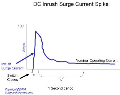
First, the OEM Engineer took the starting current of the DC motor into account when selecting the wiring size and fuse capacity for the circuit. When you start a DC motor, the initial current spike before the motor reaches running current can be over 4 times it's normal running current in some situations. By selecting a 30A fuse for a circuit that would normally only ever see 20A with all windows being operated at the same time, you allow for some margin for more than one window to be started/stopped simultaneously without blowing the fuse.

waveform-chart-dc-insrush-current-spike.jpg


Second, you mentioned that your intention is not to run major loads off each circuit, but to simply limit the demand to small portable electronics chargers. This intention lends credibility to your argument that using the window circuit is acceptable, but your design does not include a way to limit usage to what you intended.

One way to accomplish this would be to use surface mounted USB connections instead of full sized 12V supply connections. The normal rating for 12V supply connections like the one you used is 15A (which is consistent with the rating of the ACC outlet fuse), while the rating on USB charging connections is 0.5A (some chargers for items such as iPads can supply higher ratings, but devices are required to limit their current draw to 0.5A until they negotiate a higher current via communication over the data lines). Personally, I would prefer the USB connections shown below, as it will give each passenger two USB connections, as well as limit the risk of overloading.

1016.jpg


If I were going to use the full sized 12V connections, I would place a label (black printing on clear label tape) to state the current limit for each connection. You also mentioned the possibility of adding a fuse via spade connectors. I would rather use a surface mounted fuse holder or circuit breaker, so that I never have to go back into the door to change a fuse.

82-2215-250x250.jpg


I like the circuit breaker instead of the fuse holder, as if a careless passenger overloads the circuit, you don't have to go looking for a fuse to replace. You can simply scold them and tell them to press the button to reset the circuit.

S5503.gif
 
Last edited:
I understand, I just go by what information is provided and shown. You dind't state anything about soldering or finer details (I've been guilty of that and I tend to have to remember not everyone has as much technical knowledge as some of us) and I don't know your background so I erred on the side of caution and assumed it wasn't done. I apologize for that if it offended you in any way. :)

I like to make things look OEM, so I tend to stray away from extra fuseholders when there are plenty of spare slots in the OEM fuse block that just needs to be wired up (I actually spliced up the OEM foglight harness from the fuseblock to the PIAA's in my bumper for thicker gauge wiring and to use the factory fuse slot instead of running the PIAA harness.)

As for the fuses, the member before me addressed my concern about amperage draws and motor peak amperage and such. Again more or less being cautious, I tend to want to build things tougher than they need to be and expected other members (not you persay, but others who may use this mod) to load up those circuits with more than phones and such.

Its still a great mod either way.

Post Note-

I know the line about arcing and such is pretty textbook sounding, but I've seen poorly done wiring (mostly by ghetto rigged and/or crappy audio/video jobs) where the wires work loose cause issues in more than just one circuit and sometimes even arc to the body.
 
very valid points there.

what i am going to do is actually use spade connectors and add in a 5amp fuse.


so if there is a overload i can just change the fuse. i am also going to make the fuse accessible from just popping out the light in the door panel.

I really like where this thread is going. everyone is actually has something usefull to contribute to the thread!

I only say this because i am not used to this. in the volvo forums, all they do is ***** and moan and offer their opinion with no factual data to support their opinion. I am not perfect nor do i think i know everything, so i do value the intellectual discussion we have here!!
 

Members online

Forum statistics

Threads
278,312
Messages
3,554,085
Members
248,016
Latest member
Advally Service

Trending content

Back
Top