DIY MOD: Ambient lighting from map light

Thanks for clarifying. I'm not sure where/ why I came up with 15v. If I go off 12v power that goes on/ off with headlights, I can use resistors in ohms that you referenced in your post. I'm not sure if there would be any difference between using 800/ 200 or 2400/ 600. Would there be a difference with the led's output?


Thanks

there is no reason to use one over another. use what ever you have and or can get your hands on.

output will not change, thats the reason why in another post i tried to lower the output voltage to get the light to be dimmer. that didnt work :)

post pictures of your mod and experiences to get it to work. I would love to see it!
 
[MENTION=93434]gshadow325[/MENTION]
Dude the 12V outlet mod i got from you is one of my favorites. Now I gotta tear up my map light and do this one? I hate doing electrical work on my truck! lol
 
[MENTION=93434]gshadow325[/MENTION]
Dude the 12V outlet mod i got from you is one of my favorites. Now I gotta tear up my map light and do this one? I hate doing electrical work on my truck! lol

LOL, this is a nice mod. so simple and effective. i love it every time i drive at night. at first it was too bright. i used some white out to dim it and i now irs perfect!!

its a easy mod, promise it wont hurt. everything is up there!
 
thanks for the picture. i think the disconnect is that i can't tell how you have the blue resistor connecting the + and - of the LED. it looks like there is just the brown resistor for + and blue for -.

is the brown resistor wrapped around the positive lead then hooked to red?

and then the blue resistor is wrapped around the negative lead, and then the brown resistor, and then hooked to black?

thanks again for your help, just trying to clarify!

i'm not shorting them. thats not the finished connected product.

Mr. Steve,

thought i'd try one more time to see if i could get some clarification on which wires exactly intertwine with each other?
 
Mr. Steve,

thought i'd try one more time to see if i could get some clarification on which wires exactly intertwine with each other?

this is how it goes. i think this maybe the clearest i can do it. in my crazy mind it sounds right LOL. please tell me if im nuts or not hahahaha

<a href="https://www.flickr.com/photos/129154214@N04/16045278427" title="20150108_105155 by gshadow3225 .., on Flickr"><img src="https://farm8.staticflickr.com/7480/16045278427_4081763439_z.jpg" width="640" height="360" alt="20150108_105155"></a>

<a href="https://www.flickr.com/photos/129154214@N04/16043533548" title="20150108_103823 by gshadow3225 .., on Flickr"><img src="https://farm9.staticflickr.com/8579/16043533548_6e4293b127_z.jpg" width="640" height="360" alt="20150108_103823"></a>
 
this is how it goes. i think this maybe the clearest i can do it. in my crazy mind it sounds right LOL. please tell me if im nuts or not hahahaha

The above is correct. Please everyone use solder and heatshrink tubing and you will save yourself a lot of pain and hassle down the road. It would also be possible, after securing and insulating the resistors, to push/fold the wires together, twist, and wrap in electrical tape to make it one thin(ish) looking wire. Just don't bend the resistors more than once or twice or they will break off and preferable not next to the base. They are about 5% the strength of a paperclip.

On my mod list! Thanks GShadow!
 
this is how it goes. i think this maybe the clearest i can do it. in my crazy mind it sounds right LOL. please tell me if im nuts or not hahahaha

<a href="https://www.flickr.com/photos/129154214@N04/16045278427" title="20150108_105155 by gshadow3225 .., on Flickr"><img src="https://farm8.staticflickr.com/7480/16045278427_4081763439_z.jpg" width="640" height="360" alt="20150108_105155"></a>

<a href="https://www.flickr.com/photos/129154214@N04/16043533548" title="20150108_103823 by gshadow3225 .., on Flickr"><img src="https://farm9.staticflickr.com/8579/16043533548_6e4293b127_z.jpg" width="640" height="360" alt="20150108_103823"></a>

thank you for taking the time to take this picture, it is much clearer! i was confused at the earlier pic with the blue resistor.

this will be my last clarification, other than that i will just make it work and stop bothering you.

big resistor is wrapped around + output. it is then wrapped onto positive input of led bulb. the small resistor is wrapped around the large resistor, but not the + input. the other end of the small resistor is wrapped around the negative output. the negative output is then wrapped around the led neg input. or are some of these connections soldered?

thank you, i swear this is my last question, sorry for being a bother and hopefully you don't now regret posting this mod.
 
I think this will help. Three things will tie together to the positive side. 1,the other end of the big resistor, 2 one end of the small resistor, 3 the positive end of the led bulb.

On the negative you also have 3 connections. 1, negative input wire (that's the black wire in the above pictures), 2, the other end of the small resistor, 3 the negative end of the led bulb.

Further clarification, the big resistor is basically in line with the positive feed.
 
thank you for taking the time to take this picture, it is much clearer! i was confused at the earlier pic with the blue resistor.

this will be my last clarification, other than that i will just make it work and stop bothering you.

big resistor is wrapped around + output. it is then wrapped onto positive input of led bulb. the small resistor is wrapped around the large resistor, but not the + input. the other end of the small resistor is wrapped around the negative output. the negative output is then wrapped around the led neg input. or are some of these connections soldered?

thank you, i swear this is my last question, sorry for being a bother and hopefully you don't now regret posting this mod.

all of these connections are soldered and shrink wrapped if you like. i use 3m super 33 electrical tape.

if you are asking questions then my directions are not clear enough, its not your fault. asking questions is fine, i'm sure others out there NOT posting a reply but just reading the thread are thinking what you are asking LOL.
 
this is a great mod and a really awesome idea. my wife has the ambient lighting in her infiniti and i always loved the look.

how would i wire it so the ambient lighting only goes on when the headlights are on? i have no idea where to tap into for this...
 
So I went ahead and did this and ran into problems. After testing the map light wires with a voltmeter, I tapped into the 12v and ground wire per the instructions. Using 1/2 watt resistors of 470 and 100 ohms, I connected them as detailed in the drawing to a 2.1v amber led. Yes, I recalculated for the 2.1v in the link the OP sent. Hooked everything up, and nothing happened. I thought maybe the light was too dim but there is literally no light whatsoever. I tried another 12v circuit and still got nothing.

Are 1/2 watt resistors acceptable, or should I use a different wattage like 1/4 or 1 watt? Also, should i use larger/smaller sized resistors? OP said that it needs to be 1/3 of the largest one.

This is a mod that I am really hoping to accomplish, and appreciate people's input. Thanks in advance
 
Maybe I missed something, but what activates the light, when is it on and when does it go off. Thanks.

When the ignition is turned on (whenever the electrical system is on). The LED light is very dim in the daytime and will not draw much. It goes off when you turn the key to the off position.
 
Wow I thought I was the only one crazy enough to want this. I got used to the awesome ambient glow in my previous BMWs and needed the added detail in my 4Runner.

I added two leds and tied into the dash illumination circuit so they only come on with the headlights and dim with the rest of the lights using the dimmer wheel.

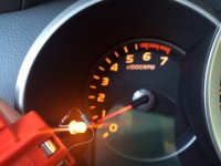
I went with an amber color that matches the dash illumination:
 

Attachments

  • image.jpeg
    image.jpeg
    95.1 KB · Views: 1,017
Last edited:
Oh and you guys are waaaaaaaay overthinking the resistor situation. I saw pictures with multiple resistors/ shorted across the LED leads? Yikes. Watch out for excessive current draw and LOTS of heat if you wire them like that....

I used a single 510ohm resistor on the cathode (-) leg of each LED. I wired both LEDs in parallel to the 12-14v illumination circuit. Simple. No mysterious burning smells or fires.
 

Attachments

  • image.jpeg
    image.jpeg
    88.1 KB · Views: 1,154
Last edited:

Members online

No members online now.

Forum statistics

Threads
278,309
Messages
3,554,075
Members
248,016
Latest member
Advally Service

Trending content

Back
Top