5280 TRail-Runner
New member
Disclaimer: I am not an electrician or work with electrical in any way. This was all put together by spending countless hours if not days looking around on the forums here and other forums and watching videos so if you plan on doing something similar, I suggest you do your own research and figure out what works best for. Now to the good stuff!
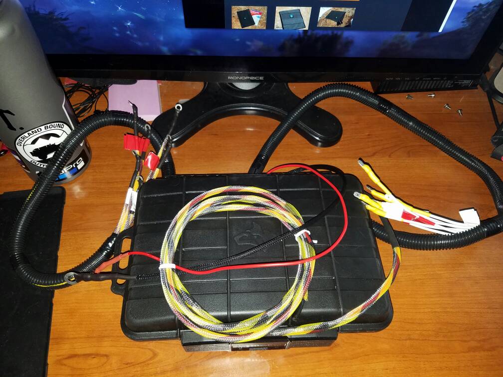
So here is my most recent project. This is a 6 relay switch box that will connect to a 12 slot Blue Sea fuse box once everything is installed. I have 6 relays all wired up and ready to go. I only have 4 switch currently but as I get more accessories, I’ll figure out a solution as to how to mount the additional switches. I do not see myself using anything more than 6 and all of which will mostly be lights pulling pretty low amperage. As for any bigger accessories pulling more than 30 amps, those will use an inline fuse which will connect directly to the battery.
I had originally built one that was a way more simpler but after it was done, I decided I didn’t like it and that I wanted go with something that was enclosed and out of the elements. I found a thread on Tacoma world and that got the wheels churning inside my head and after many hours or careful planning, the outcome is what you see below. (I’m not sure I am allowed to link other forums or not. I don’t see it being an issue but will refrain from doing so but I will share if requested and if allowed.)


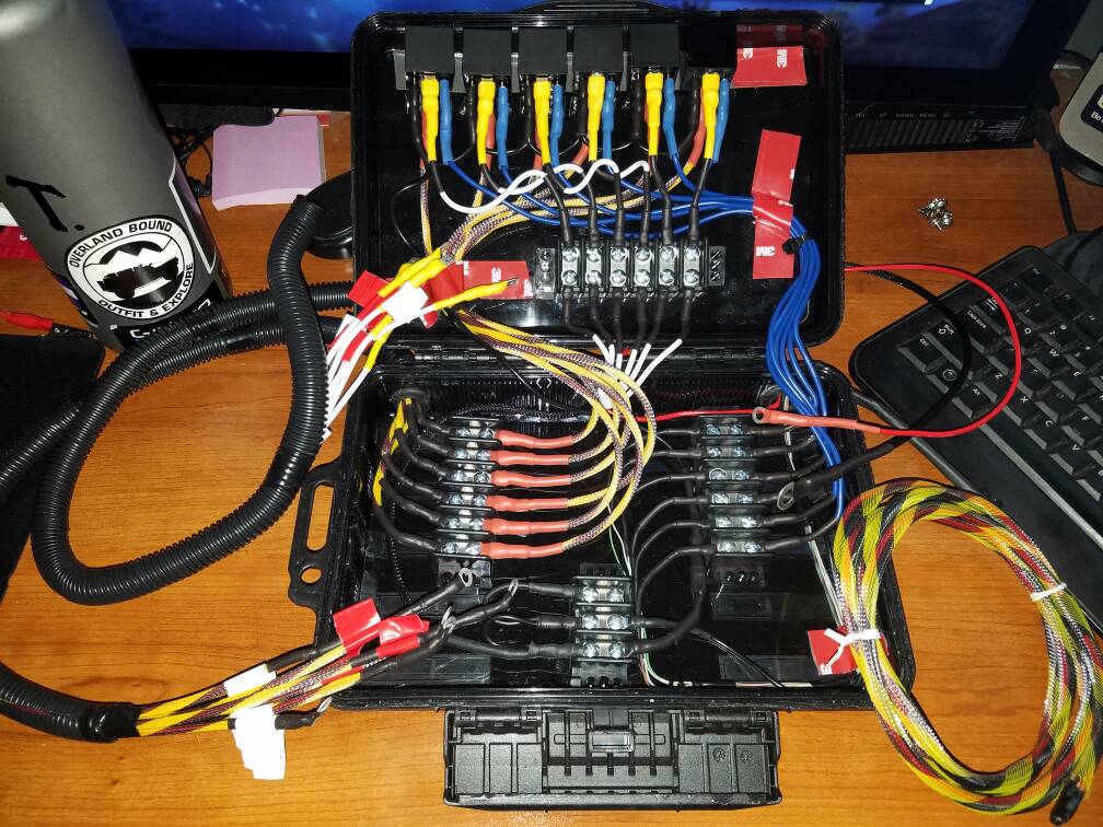
If you understand anything about how relays work then you’ll know what is going on here. If not, I will try my best. At the top, you have the 6 relays. I am using a 4 pin relay but there are different variations. I won’t get into the technical stuff but research it if you are interested.
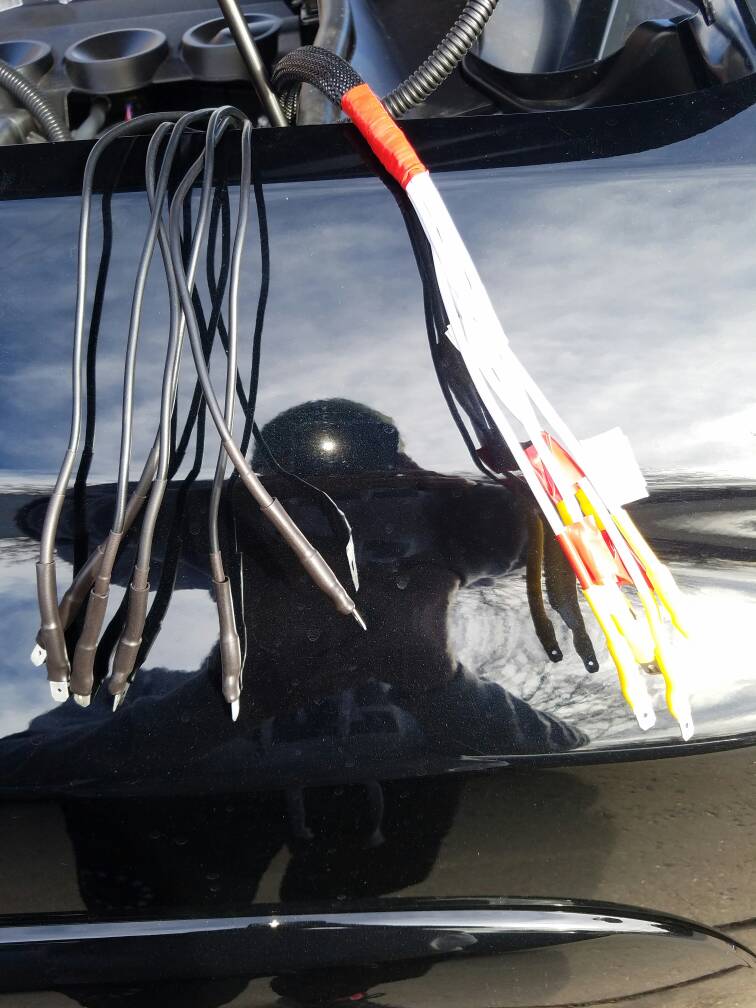
The top terminal block is the “accessory”. The top wire is connected to the relays. The out is the bottom wires which is wrapped in a wire loom with the red and white tape and quick disconnect terminals. The idea behind this is when I connect an accessory, all I need to do is slide on a heat shrink and attach a female disconnect and heat gun and done.
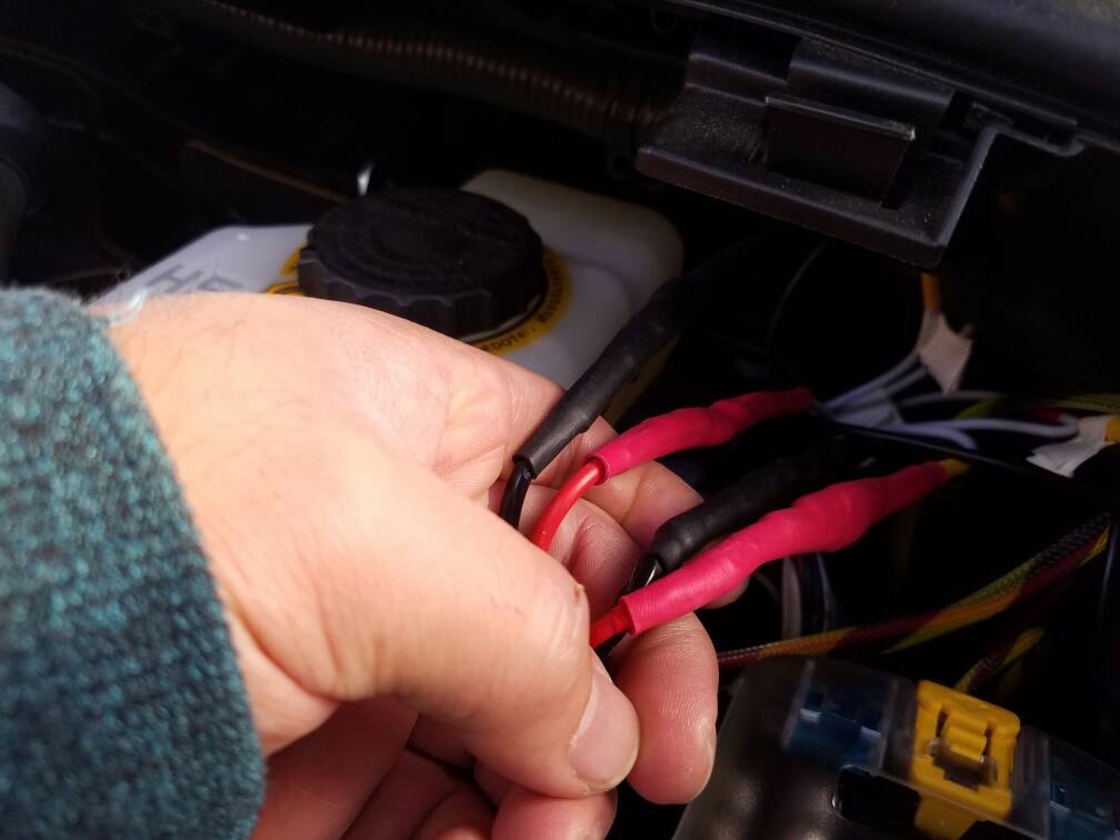
Bottom left terminal block is the “power”. The left wires with black heat shrink power coming in from the Blue Sea fuse box. Right wires runs with red heat shrink runs to the relays to power them.
The bottom terminal with 3 is the ground terminal. I have 1 ground wire from the chassis ground coming in daisy chained. 1 is used to ground the relays and the other is ran with the switch wires.
The right terminal is “switch”. The left wires will run through the firewall. The right wires that are blue run to the relay. All of the switch wires are wrapped in flexo PET.
For my switches, I do like the idea of being able to dim the switches but I am hesitant to tap into the factory wires as I do not want to void the warranty as my car is only about 3 months old. However if I do I would probably go with the posi-taps as that seems to be the least damaging/detectable method. So to power my switches, I have a ground and power wire running with my switch wires which will ground and power my switches. I may end up putting the power for the switch on a fuse tap so they only work when the car is on. I can see the pros and cons for both but we’ll see what happens once I can actually field test it more. As for my switch wires, I didn’t want to run thick wires and end up with a huge hole in my firewall so I ended up cutting open an old CAT5 cable and used the wires inside of it for the switches. This help reduces the size of the switch wires significantly.
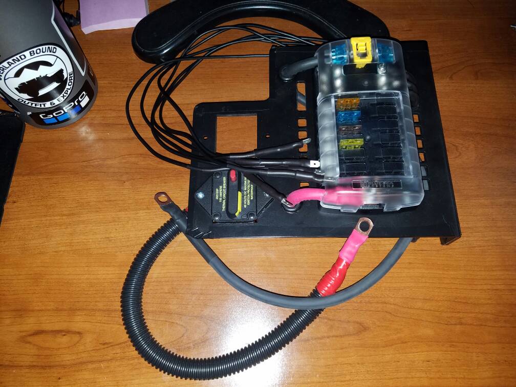
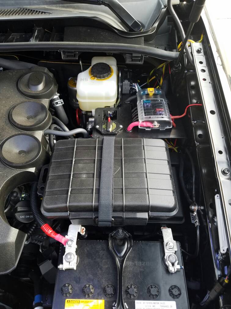
Here a picture of the fuse box on a Pelfreybilt mount designed specifically for this fuse box and 2 circuit breakers.

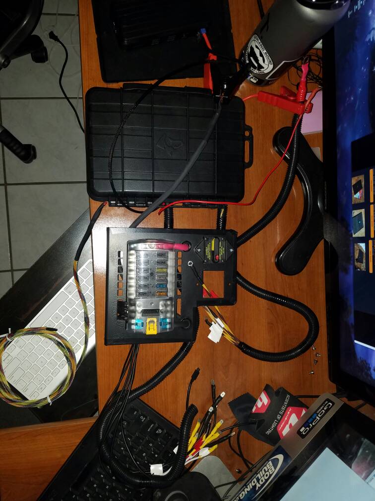
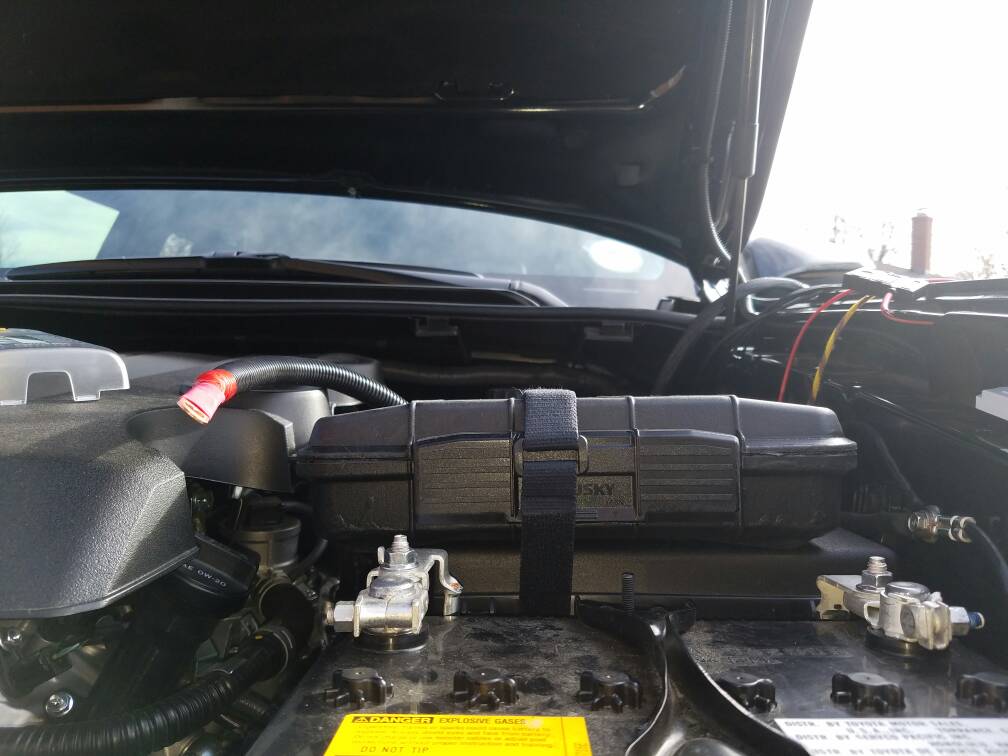
And here is a mock up of how it will look once installed. The relay box will sit on top of the fuse box and the Blue sea will be mounted to the engine bay via factory holes.

I am hoping to get this installed tomorrow so I will post pictures once its all done. Sorry for the long post but figured I' get my post count up and didn't want to do it by posting a bunch of small meaningless posts. Feel free to ask any questions or give any critiques.
Happy New Years everyone! arty:
arty:
Cheers!
So here is my most recent project. This is a 6 relay switch box that will connect to a 12 slot Blue Sea fuse box once everything is installed. I have 6 relays all wired up and ready to go. I only have 4 switch currently but as I get more accessories, I’ll figure out a solution as to how to mount the additional switches. I do not see myself using anything more than 6 and all of which will mostly be lights pulling pretty low amperage. As for any bigger accessories pulling more than 30 amps, those will use an inline fuse which will connect directly to the battery.
I had originally built one that was a way more simpler but after it was done, I decided I didn’t like it and that I wanted go with something that was enclosed and out of the elements. I found a thread on Tacoma world and that got the wheels churning inside my head and after many hours or careful planning, the outcome is what you see below. (I’m not sure I am allowed to link other forums or not. I don’t see it being an issue but will refrain from doing so but I will share if requested and if allowed.)


If you understand anything about how relays work then you’ll know what is going on here. If not, I will try my best. At the top, you have the 6 relays. I am using a 4 pin relay but there are different variations. I won’t get into the technical stuff but research it if you are interested.
The top terminal block is the “accessory”. The top wire is connected to the relays. The out is the bottom wires which is wrapped in a wire loom with the red and white tape and quick disconnect terminals. The idea behind this is when I connect an accessory, all I need to do is slide on a heat shrink and attach a female disconnect and heat gun and done.
Bottom left terminal block is the “power”. The left wires with black heat shrink power coming in from the Blue Sea fuse box. Right wires runs with red heat shrink runs to the relays to power them.
The bottom terminal with 3 is the ground terminal. I have 1 ground wire from the chassis ground coming in daisy chained. 1 is used to ground the relays and the other is ran with the switch wires.
The right terminal is “switch”. The left wires will run through the firewall. The right wires that are blue run to the relay. All of the switch wires are wrapped in flexo PET.
For my switches, I do like the idea of being able to dim the switches but I am hesitant to tap into the factory wires as I do not want to void the warranty as my car is only about 3 months old. However if I do I would probably go with the posi-taps as that seems to be the least damaging/detectable method. So to power my switches, I have a ground and power wire running with my switch wires which will ground and power my switches. I may end up putting the power for the switch on a fuse tap so they only work when the car is on. I can see the pros and cons for both but we’ll see what happens once I can actually field test it more. As for my switch wires, I didn’t want to run thick wires and end up with a huge hole in my firewall so I ended up cutting open an old CAT5 cable and used the wires inside of it for the switches. This help reduces the size of the switch wires significantly.
Here a picture of the fuse box on a Pelfreybilt mount designed specifically for this fuse box and 2 circuit breakers.

And here is a mock up of how it will look once installed. The relay box will sit on top of the fuse box and the Blue sea will be mounted to the engine bay via factory holes.

I am hoping to get this installed tomorrow so I will post pictures once its all done. Sorry for the long post but figured I' get my post count up and didn't want to do it by posting a bunch of small meaningless posts. Feel free to ask any questions or give any critiques.
Happy New Years everyone!
arty:Cheers!
Last edited: