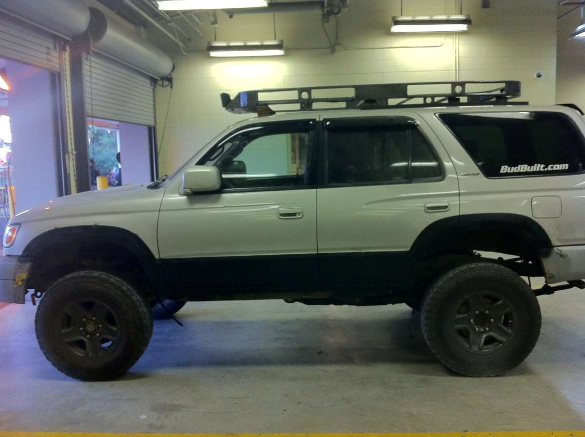
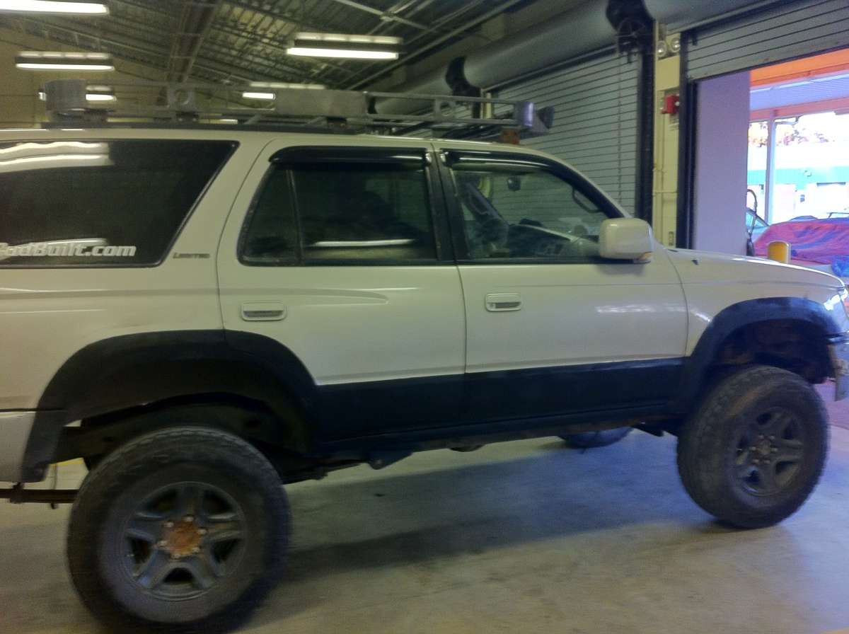
Doc's mod thread.

Doc2012

Senior Member
OK Gents.

I know I have a build thread, but this is going to be a little different.

I've seen a couple posts lately where newbies keep asking about mods. This mod will be strictly MODS. No builds. From the simple mods, to the more expensive. I figure that not everyone wants to go through a build thread, just to see what small stuff has been done, or where a good place to start is.

If there's something on here you want to know more about, feel free to contact me about it. I'm an open book when it comes to my work.

Now, lets kick this off.

Technically, a "mod" is anything that is not stock. So, anything you can think of can be done.

There are many mods to be done. Some are as simple as bridging a relay, others are much more complicated. Some cost a couple dollars, others, perhaps 100+.

The first "mod" I did was to ditch the 265/60's, and get a more aggressive, slightly bigger tire. I went and got the Falken Rocky Mountains. Great tire, awesome traction, great wear, IMHO. Glad I made that choice. Next set will be the same tires, in a 285.

The next mod I did was to paint my rims. I got some graphite rim paint from one of the auto places, and went to town on my other set of rims.

This is what they looked like before.

asu3e5un.jpg


The paint was coming off the center cap, and there were a lot of blemishes.

So, I took some 280 grit, an went to town.

Here they are painted.

eguvy4em.jpg


And here they are mounted.

5anyza2u.jpg


The next mod was the full time power out let mod. All I did was took some 11 ga wire, two male clips, and jumped the power outlet relay. Just be careful when you do this. If you leave something plugged in too long, you will kill your battery.

The yellow wire is the jumped relay.

gumabaju.jpg


The next was to get rid of the stock double din, and get a better radio and speakers.

I choose to go with Rockford Fosgate 6.5" in the front, and 4.5" Clarions in the rear. I will soon be swapping out the rears for some 6.5", and will update as I do that and mount them.

For the head unit, I went with a JVC Arsenal, with BlueTooth and a rear iPod cable. I choose to go with the rear cable to keep the cab a little less cluttered.

Here's the radio. I also wrapped the wood trim in some RealTree AP fabric.

heqy9u5y.jpg


Next I did some lighting in the rear.

I went to Walmart, and got two packages of those little LED strips for 20 bucks. Not bad, considering they light up the rear like day light.

The first pic is how I wired them. I twisted like wires together, and then added a little solder to make sure they didn't move. I wanted to keep the on/off/door function, and this is what I came up with. The others are just the lights.

u6avezy3.jpg


eju3udeq.jpg


gyhyqyry.jpg


bu9eda5y.jpg


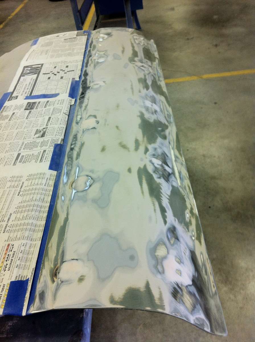
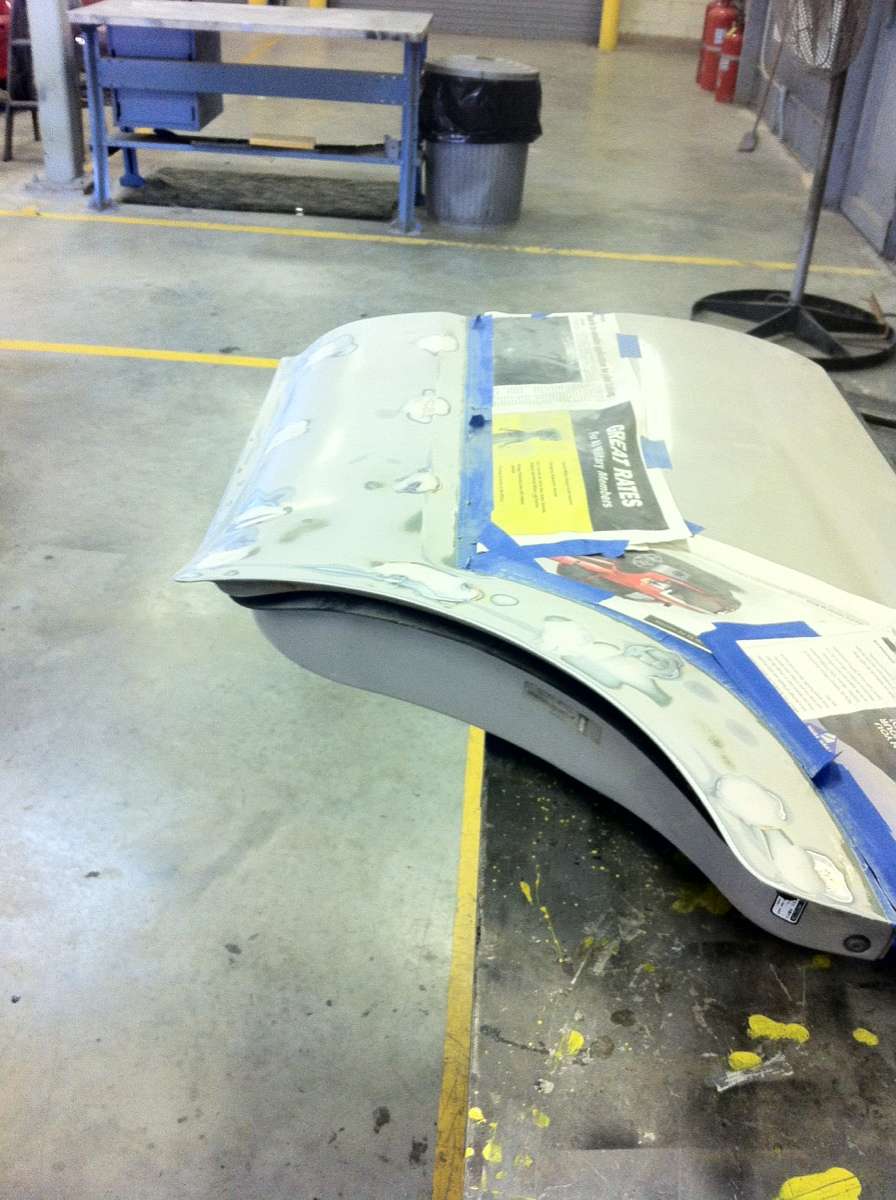
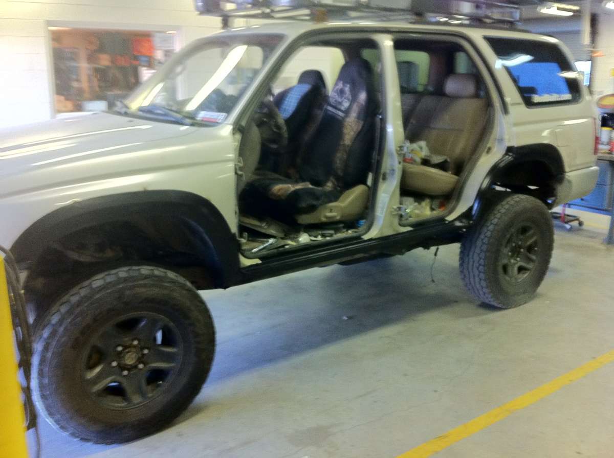
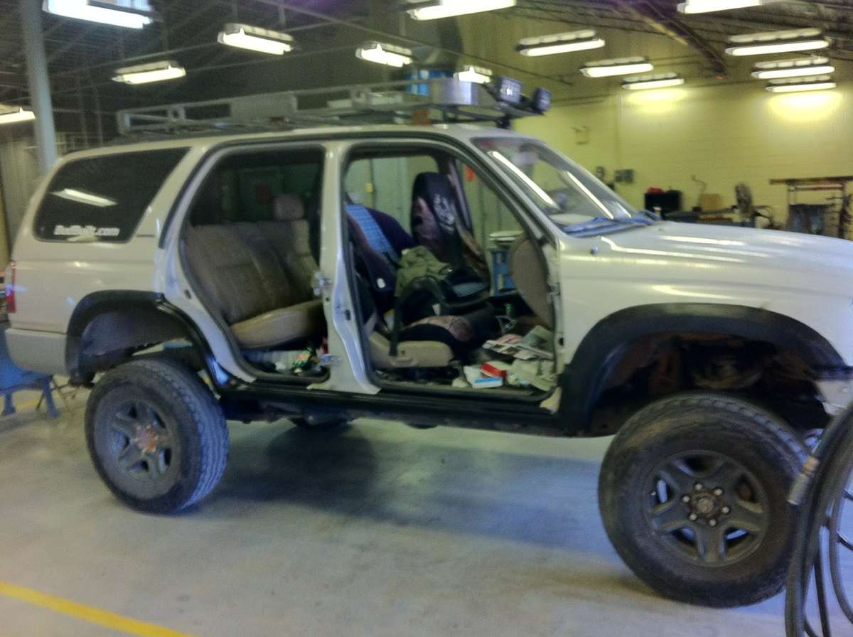
I've always wanted half doors, or no doors. But, since they don't make mirror relocation brackets for Toyota, I went with the half doors.

Obviously, and hopefully this goes with out saying, you need to gut the doors. If you decide to do this with the stuff in there, you're dumb.

And, for the love of whatever you believe in, don't do this on your stock doors. These doors came off my donor truck when I did my 4WD swap.


First, I measured where I wanted to remove metal, then I taped it off.

uzege6ud.jpg


pyny6y7e.jpg


Next, I cut them out.

y5erabun.jpg


I added some metal, smoothed them out a bit, and here's how they sit now.

uhatezyt.jpg


I have plenty more mods, but I'm on my phone right now, and can't get to the other pics I have. As soon as I can get to a computer, I'll add more to this, and I'll keep adding as I go along.

Like I said before, any questions, feel free to ask.
 
Register to hide this ad
That's not all my list, but thanks! Just the pics that I can get to on my phone. I plan on doing a write up in getting rid of all the ADD stuff, the BudBuilt clocking ring, ABS delete, and a few other mods. Just gotta get the pictures. Damn hurricane. >:|
 
I like what you did with the rear LED's, how did you wire the positive and negatives of the led strip to the fixture though?
 
hesupusa.jpg


The switch is toward the right.

If you take that switch off, you'll see there are two metal tabs that hold the light bulb in.

I twisted like wires together, then put the positive where I have marked, and the negative where I have marked. I just wrapped them around the metal tabs, then soldered them together so they wouldn't come loose.

I have the wires from the LEDs tucked up there. Those lights came with 10 feet of wire, so you can cut them, or just tuck them away. I can try to get more pics if you need them. Just gotta let Sandy do her thing first.....
 
hesupusa.jpg


The switch is toward the right.

If you take that switch off, you'll see there are two metal tabs that hold the light bulb in.

I twisted like wires together, then put the positive where I have marked, and the negative where I have marked. I just wrapped them around the metal tabs, then soldered them together so they wouldn't come loose.

I have the wires from the LEDs tucked up there. Those lights came with 10 feet of wire, so you can cut them, or just tuck them away. I can try to get more pics if you need them. Just gotta let Sandy do her thing first.....
oh, i see what you mean, you wrapped the positive and negative from the led strips to the leads in the fixture.. and it provides an appropriate amount of power huh, very nice! i have a 48 5050 led panel in there now, but i feel like your light distribution is pretty good
 
OK Gents. Here's a couple more Mods for ya. There will be plenty more to come, so don't you worry.

Manual Hub Swap: Swapping to manual hubs is the best thing I can think of for a WW/DD. IF you break a CV, all you have to do is pull it out, cover the hole in the diff, and the hub, and you’re good to go. With the ADD, you HAVE TO replace the CV in order to keep driving. That creates a couple problems, but I’ll let you guys figure those out. :p
Of course, you can always do a SAS, but we’ve all heard the horror stories of those.

Manual diff:The ADD front diff is all electric. Yes, there are those that are vacuum actuated, but how do those vacuum’s occur? Electric pumps. The difference between a manual diff and a ADD diff is nothing more than the passenger side tube, but good luck trying to find someone that will sell you just the tube. I found a way to make the ADD tube a “manual” tube, using nothing but a hose clamp.


First things first:

I DO NOT take responsibility for anything that might go wrong from you doing the mentioned modifications. While I have not had any problems with my vehicle from these mods, I can not be responsible for anything that happens to your vehicle.

Manual Hub Swap

The Manual Hub Swap is probably the easiest mod you can do. You need to get Manual CVs, and the hubs. That’s it. Now, this would be the OPPORTUNE time to change lower and upper ball joints, as well as your outer tie rods. It’s all going to be taken apart anyway...

First step is to get everything together. Obviously, you’ll need the manual hub from a first gen TACO. Our 3rd Gen 4Runners and 1st Gen Tacos are basically the same component wise. So, these parts are interchangeable. I’m pretty sure that I’m running ’96 hubs in my ’99 Limited. I know for a fact that they’re not from a ’99 Taco, but an older one.

There are two options you have to get this swap done. First, you can use the Taco spindle, or you can get the hub pressed out and pressed into the 4Runner spindle. The easiest way to get this done, since it’s a bolt and go, is to use the Taco spindle. Just make sure the bearings are good. To get my bearings changed out in my spindle, I was quoted over $300, per hub, from the stealership. I went to my local NAPA, and had them press them out for 20x less than that. Cost me 30 to get BOTH done, plus the cost of the bearings from the parts store. I did have to by the Toyota Lock Nut Tool, but that was worth the 15 bucks.

You next need to decide if you’re going to be doing the UBJ, LBJ, and OTRs. This is the point where you want to figure that out. It can never hurt to do them. I got all mine from Advance, and the LBJ came already pressed into the piece that bolts to the spindle. Similar to this:

lbjk.jpg


That made life a lot easier.

You’ve got the spindle, take it to NAPA and have them press out the old UBJ, and press in the new UBJ. (If you got a new one.) Shouldn’t be more than 5 or 10 bucks for them to do it. Then, put the OTR onto the LBJ assembly, and you’re ready to go.

First thing you’re going to want to do, before you do any of this, is SOAK the UBJ and LBJ in some PB Blaster at the control arms a couple days before you do this. At least over night. And spray the SH!T out of them. You’ll be amazed how well that stuff works, and how much it helps.

Now you’re ready to get to work!!

The first thing you’re going to want to do is to loosen up the lug nuts. I know I don’t have an impact, so the easiest way for me to do this is with the weight of the Runner on the tires. Just break them loose, don’t take them all the way off.

Next, jack up the front and make sure it’s supported. Obviously it would freaking suck if this thing fell on your legs and crushed them.

Finish taking the wheels off.

Drain the front Diff. When you take the CV’s out, it’s gonna leak all over you if you don’t. Ask me how I know……

Now you need to take the brakes off. You CAN just unbolt the calipers, move them to the side, and then pull the pad off, but the chances of breaking a line are MUCH higher than if you unhook everything. But, then you need to bleed your brakes to and all that. BUT, the choice is yours.
You see the metal cover that is on the hub? Yeah, that one. In the center. You need to take that off, and under it there should be a large nut(BAHAHAHAHAHAHA!). It should have a little cover over it, with a carter pin through it. That is what holds CV in the diff. Once you get that nut off(LMFAO), you should be able to GENTLY tap that CV and it will slide in and out of the Hub. It won’t come all the way out because of clearance issues, but it should slide in there.

The next step is up to you. I went with the LBJ, but you can do the upper. I’ll go with my method, because, well, it’s what I did. :P

To remove the LBJ, remove the carter pin and castle nut securing the LBJ to the Lower Control Arm(LCA). Next, loosen the 4 bolts that hold the LBJ assembly to the spindle. The spindle will be loose, hanging by the UBJ. You should be able to either press the LBJ with a BJ press(available at Advance or AutoZone), or use a BFH to hit that b!tch out of there. Just be careful hitting it. The LCA WILL bounce. Again, ask me how I know…… :/ (I was hanging around Marines for FAR too long when I did all this. It’s always a bigger is better thing with them…..)

Next, take the “lock nut” from the OTR and loosen it. Mark where the OTR is, and then take it off. There is your LBJ assembly.

Take the carter pin and Castle nut off of the UBJ. Use a press or a BFO to knock that b!tch loose.

The Spindle should be off. It should be in your hands right now. Throw it to the side. You don’t need it anymore.

Next, Get under the truck with a pickle fork, or two large screwdrivers. Place the Pickle fork in between the CV and the diff, and whack it. The CV should come out. It should be in your hands right now. Take the dust cover off. Throw the CV thing to the side. You won’t need it anymore.

Now, for the other side, just repeat. Hahaha. Thought I was gonna say something else huh? GOTCHA!!!

OK. You’ve got the Manual Spindle all set up and ready to go, right? All your parts are there, all your bolts, your UBJ pressed in right? Good. Let’s get to it.

Take the CV, And reinstall it into the diff. MAKE SURE THE DUST COVER IS ON THERE!!! The easiest way I found to do this is to leave the “C” clip facing down, then wiggle and push that thing in there. You’ll notice when it goes in.

Install the OTR to the LBJ. Torque castle nut to 67 FT LBS. Insert carter pin.
Next, take your LBJ assembly and thread it onto the Tie Rod. That mark you made last time? Yeah, the one I told you to make when you were taking that thing off? Go to that point. It should keep your alignment somewhat straight.

Put the LBJ into the LCA, and put on the castle nut. Torque to 112FT-LBS. Put in the carter pin.

Take the steering knuckle and place the UBJ into the hole in the UCA. Put on castle nut, and torque to 80 FT LBS. The Steering Knuckle should be hanging from the UCA again.

Take the CV, and line it up with the hub. It should slide right in there. If you, you might have to rotate the hub a little to get the splines lined up right.

The easiest way I found to do this next step is to get a ratchet strap, and loop it around the UCA and LCA. Tighten the strap, making sure that the bolts holes in the LBJ line up with the bolt holes in the steering knuckle. When you have them close enough that the bolts will reach up through there and grab onto the steering knuckle with enough threads, you should be good. Take that bolt out, use BLUE LOCTITE, and reinstall; torque to 59 FT LBS. Complete with the remaining bolts. Once those are all in there, you can remove the ratchet strap. The steering knuckle should be secured to the LCA, LBJ, and UCA.

Reinstall Brake Pad; torque Caliper mounting bolts to 90 FT LBS.

There are 6 10mm bolts on the front of the hub. Take those off. You should have a 12mm screw with a washer at the end of it. That threads into the HUB end of the CV, keeping the CV inside the hub, in case of a snap or over flex.

Repeat the same steps for the other side.

Bleed brakes, refill Diff, and your manual hubs are on and ready to use.


Oh yeah.... GET AN ALIGNMENT!!!


I'll try to get pics up at some point. I kinda need some one with ADD to be able to do that though.....


ADD to Manual Diff Conversion

Now, even though your manual hubs are on, you still have the ADD. The ADD works by way of a fork moved by the actuator, which moves a sleeve to make the passenger side wheel spin at the same time as the driver side wheel. Basically, your truck is 3WD, until you engage the ADD. The driver CV always spins, and so does the front shaft. When you hit the 4WD button on the t-case shifter, that engages the center locking differential, as well as sliding that fork over to make the passenger wheel spin.

I found a simple way to make the ADD diff the same as a manual diff, using nothing more than a hose clamp. It’s your call if you want to do this, but, like I said, it’s one less thing to go wrong on the trail. You’re going to want to do this when the front diff is empty, so right after you get the hubs set up would be a good time.

Take the actuator, and all hoses and electrical connectors off of the passenger side tube on the diff. There are 6 bolts that need to be removed to take all the crap off.


arrowk.jpg


With the ADD DISENGAGED, notice where the fork is. Slide it around to make sure it’s not binding up anywhere, and it’s not stuck.

disengaged.jpg


Move the fork over to the “engaged” position.

engaged.jpg


Put the hose clamp on the shaft, to make sure it doesn’t slide back into the “disengaged” position. The green arrow is where the hose clamp should go.

engagedandclampposition.jpg


Slide the sleeve in the tube over to so the fork is in the proper position.

engagedtube.jpg


Use some gasket maker, and go around the actuator.


Bolt the actuator back to the tube, and torque the bolts to, I believe, 50 ft LBS.

photo8go.jpg


Obviously, you'll want to cover those two air lines, as well as the electrical connector. The air lines, obviously so water doesn't get in there when you're wheeling, but the electrical, just incase you want to change it back to ADD. Why you'd want to do that, I have no idea....


You not have a manual front differential. :D
 
Last edited:
Ok guys.

Here's another mod for ya.

I guess this is more of a cosmetic thing, but I'll explain.

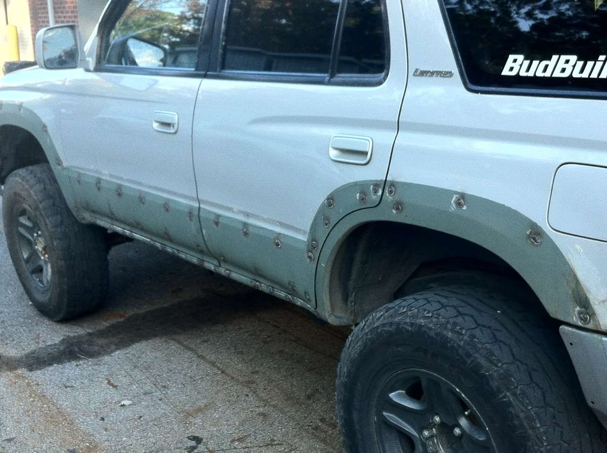
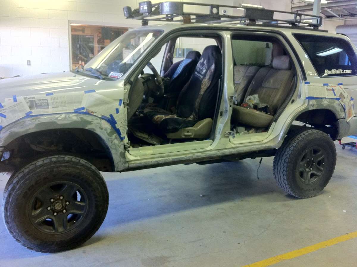
The way I see it, the flares in the Limiteds are a nice touch. IMHO, for a DD, they're great. But, for those of us that wheel, they can be a huge down fall. They stick out about two inches, and those two inches could be the difference between getting through an obstacle, or loosing some paint or denting the body. Couple that with the rarity of actually finding one of these flares if you damage one, and you've got a bit of a predicament there.

Now, this mod is time intensive. I've got probably 30 hours into this mod.

You're going to need a welder, Bondo, sander, and either bed liner or paint.
I choose to go with the Rustoleum Undercoat. Seems to be working pretty well. Again, the choice is yours as to how you want to finish this.

I wanted to do this a long time ago, when I first took the flares off, but time wouldn't let me. So, what I did was paint the are where the flares were so I'd have the outline. Actually, I left the flares on there, and taped off the area around them before I removed them, so I would have the out line.

Here's what I had then the flares were removed and the tape was off:

photooct13121304.jpg


photooct13121411.jpg


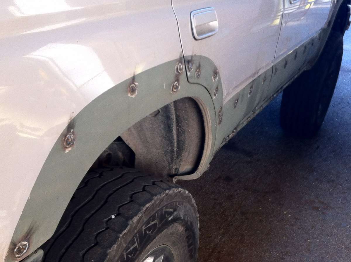
See all those holes along the doors, fenders, and rockers? Yeah, those are all from the Limited panels and flares.

How did I fill those in you ask?

I welded them all shut.

photonov21151718.jpg


photonov21151733.jpg


That was FUN!!

After that, I took a grinder and smoothed them out. Didn't take a Pic of that, but I'm sure you can imagine what it looked like.

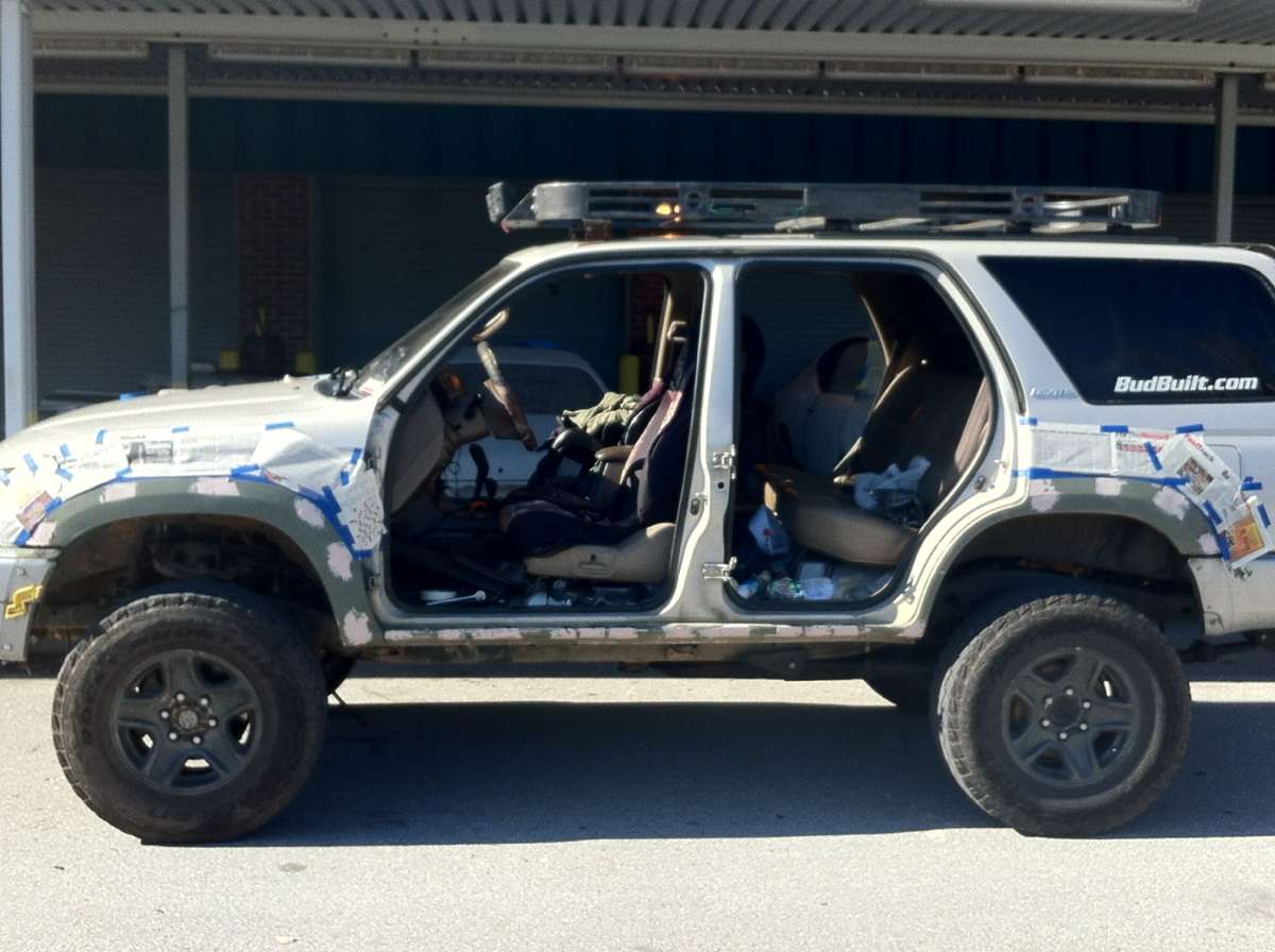
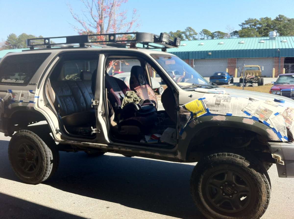
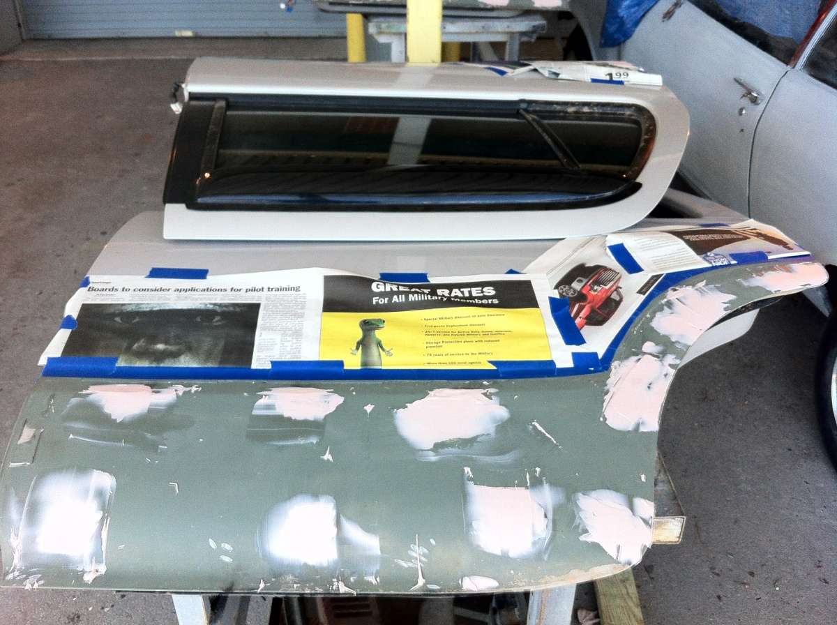
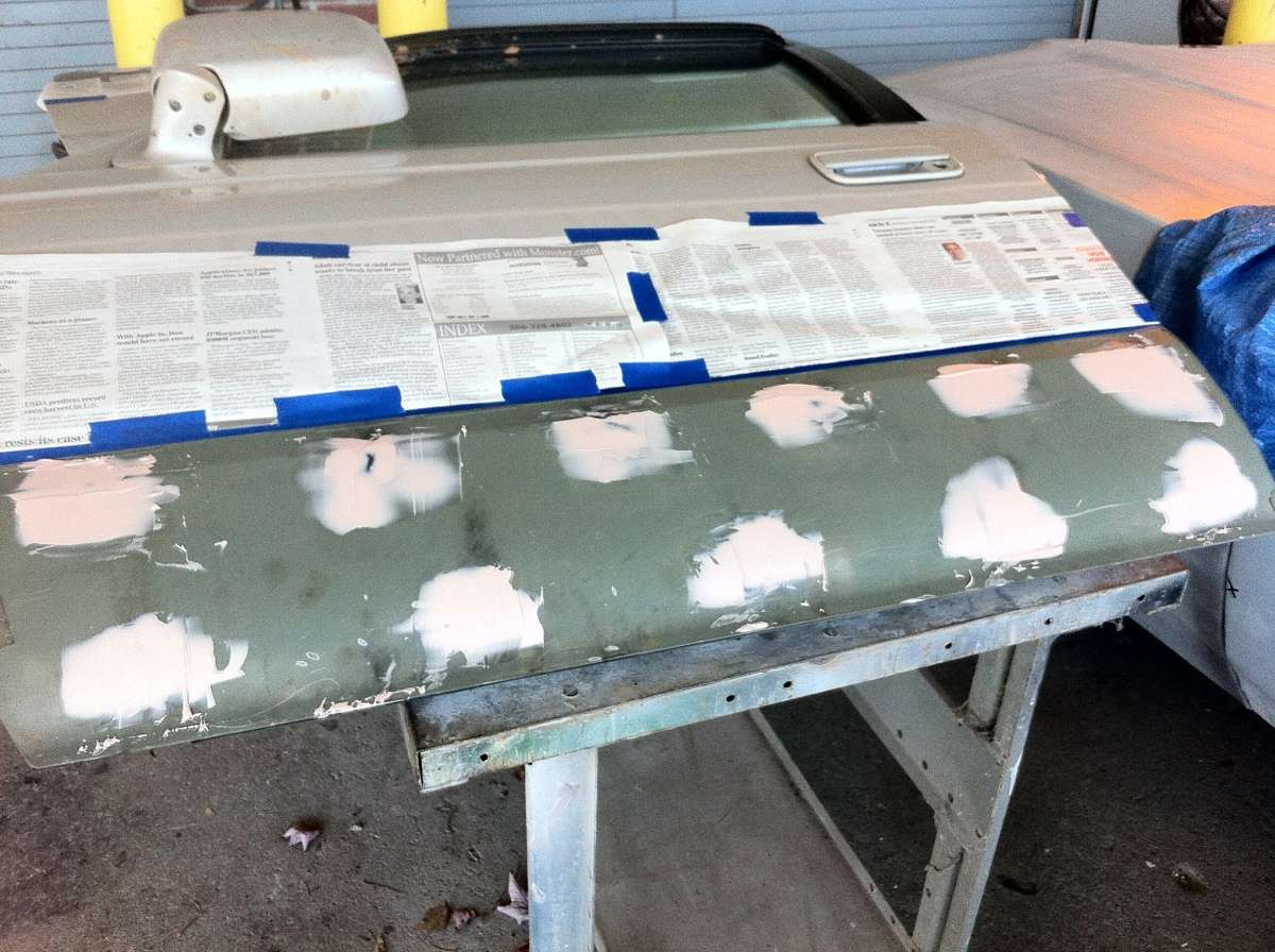
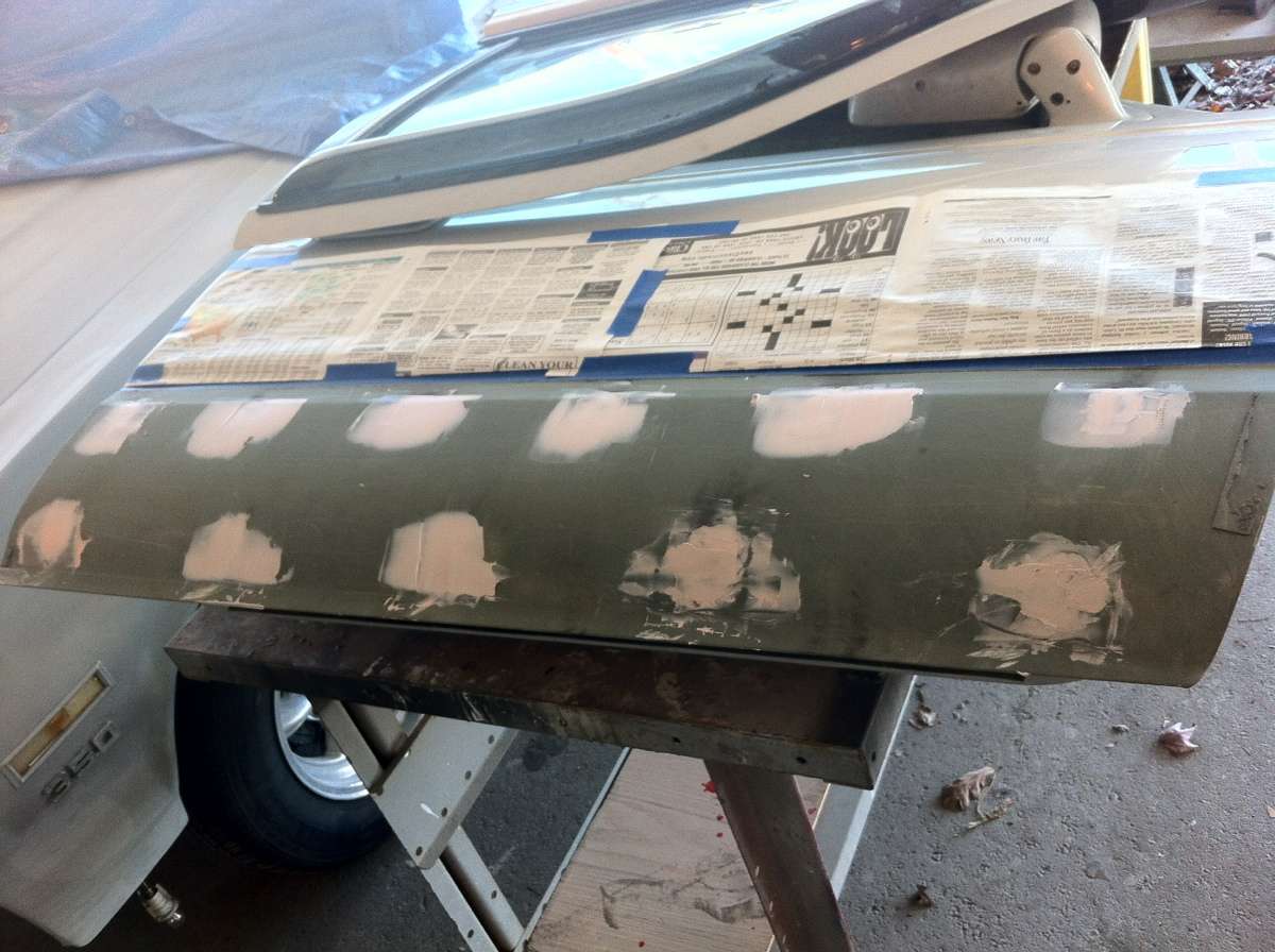
Then, I taped off the area again, and added news paper to the rest of the body to prevent overspray from getting on there. Next was to Bondo, or mud, up all the areas that were grinded off, to give the body a nice, smooth look:

photonov24115737.jpg


photonov24115754.jpg


photonov24115806.jpg


photonov24115814.jpg


photonov24115822.jpg


photonov24115830.jpg


Then LOTS of sanding:

photonov24145744.jpg


photonov24145756.jpg


photonov24145813.jpg


photonov24145820.jpg


photonov24145820.jpg


photonov24145827.jpg


photonov24145840.jpg
 
I still had some high and low spots, but I could live with them.

Then, I sprayed it with the Undercoat, and took off the tape before it cured.

photonov24153152.jpg


photonov24153209.jpg


photonov24153220.jpg


photonov24153228.jpg


photonov24153234.jpg


photonov24153234.jpg


photonov24153240.jpg


And the final result:

photonov24163256.jpg


photonov24163308.jpg


Could I have gone about it differently, Yes. I could've found a different way to fill the holes in, then used the Bondo and done it that way.

But I'm happy with what I have. Not only does it look like a normal door, but it also gives the door some rigidity, though slight.

As always, any questions, feel free to ask.
 
Last edited:
I said this was going to be added to my added to my build thread, but decided to add it to my mod thread instead, then add my mod thread to my build thread signature.

Took the truck out today, and wouldn't ya know it, the damn alternator shat the bed. Well, IDK if it really did, I probably could just clean it up, but what the hell. Didn't want to risk it going out again with the girl and baby in the car.(Read PERFECT time to do an upgrade.)

So. I upgraded. (girlfriend stole the laptop, just so I can add that he should of typed, "perfect time to con the GIRLFRIEND into paying for an upgrade!" :P)

Went to Advanced Auto and got a CS-144 from a 1995 Cadillac Deville with the heated windshield. Also bought the harness for the alternator.

The stock alternator will put out 85 Amps. The Cadillac one will put out 140.

First thing to do was to build me a little stool. My short ass can't get into my engine bay all the way, so I had to come up with something. 30 minutes of cutting and welding later and I had this:

photofeb12153822.jpg


Step 1 is to remove the stock alternator. Here's a shot of the two next to each other.

photofeb12162030.jpg


photofeb12162042.jpg


photofeb12162057.jpg


There is a nice size difference in the two.

Here was the tricky part.

The harness I got from the store was one color. All black. The wires, plug, it all was black.

With a little research, I figured it out.

If you look on the plug, there is an S, F, L, and a P.

S is the Sense wire. This is also the thickest wire. This wire goes to the white wire on the Toyota harness.

The F wire is the field/ignition wire. This will go to the red wire on the Toyota harness.

The L wire is the lamp wire. This will go to the yellow wire on the Toyota harness.

P is the stator wire, though there isn't one. It's used to run older style tachs.

There are 4 prongs, but only three wires. Don't ask me why.

Now, you can do two different things here.

You can work in the small area I the engine compartment and try to splice the wires together.

OR, you can do what I did.

I cut the Toyota connector of the harness. :o

Then, I stripped all the wires. I mean ALL the wires. All 9.

Then, I took the CS144 harness, and attached it to the Toyota connector. I stripped the white wire further than the rest, because I had to solder the white wire on to the thick wire of the CS144 harness. Didn't take a pic of this part.

With the other two wires, I just twisted them together.

Then, I bought some weather proof butt connectors, and put them on the end of the CS144 harness. Here's what I had:

photofeb12173600.jpg


Then, I brought that over to the front, and put the harness on the other side and crimped it down.

photofeb12174029.jpg


The only wire you NEED to connect is the yellow wire to the L wire. I just went ahead and did all three.

Now, those "weather proof" connectors are basically shrink wrap. So, the obvious comes into play here. Shrink it.

The reason for keeping the stock connector was incase I ever decide to go back to a stock alternator.

Now, when you put the alternator in, you're going to run into a space problem. Simply solution for this.

Loosen the bottom bracket bolt from the block. Here's a pic. It's a 14mm bolt. The bolt is in the socket, the big silver thing. ;)

photofeb12174415.jpg


Now that that's out of the way, the alternator will slide in easy.

Now, you need a spacer. I used three washers, and tacked them together. A pic:

photofeb12175524.jpg


You need to do one of two things with the post connector. You can either drill it out and bend the tabs, or cut it off and put a different connector on there.

I chose to drill and bend.

After that, put the bolts in, put the tensioner back, plug it in, and you've got a upgraded alternator. More pics.

photofeb12184717.jpg


photofeb12184717.jpg


The CS144 has a 6 rib pulley on it.

The Toyota has a 4 rib pulley.

You can see if you can replace the pulley; you'll need a pulley with a 17mm hole, the size of the bolt on the CS144.


She's gonna hate me for this, but I'm gonna throw these in there too. Best woman I could ask for. Beth.

photofeb12162137.jpg


img0957.JPG


img0954ki.jpg


img0955b.jpg
 
This is an awesome thread Doc, keep it going!! I didn't see mention of the post swim mod....lol
:wow2::bolt:
 
Here's another write up for you guys.

This is the Speedo Mod.

Basically, what Toyota did, and don't ask me why, was to run the speedo sensor through the ABS. How it works, I really don't know, but I do know it has something to do with the pulses of the ABS ring. And that's all I care to know, honestly.

When I did my Manual Hub Swap, and my 8.4" in the back, I completely lost my ABS, so there went my speedo. Drove around for a while with no speedo, using an app on my iPhone, and the RPMs of the truck to gauge how fast I was going.

Finally, I found the parts I needed from a guy who was willing to them off of a wrecked Taco.

When I did this mod the first time, I didn't realize what a half-assed job I did, until I got under the truck today to replace my wiring harness. (Special thanks to [MENTION=78895]DeathCougar[/MENTION] for having the right harness, and his timely delivery of it!) Hopefully that will fix my CEL that I've been having a problem getting rid of. :shrug:

Here we go:

Parts needed:

Speedo sensor out of a Tacoma. Any year will do. If you're running different gears like I am, then you don't really need to worry if the gear is right. My speedo is 16% off because of the 4.88s that I'm running. If you're running stock gears, see if you can get one from a Taco with your gearing. That should keep your speedo pretty damn accurate.

18ga Wire, a lot of it. You can use one color, or you can use three seprate colors. The choice is yours.

Wire cutters/strippers. :girl:

Butt-Connectors or Soldering Iron and solder.

Shrink Wrap- again, lots of it.

Now, first thing you want to do is to take your gauge cluster out. If you don't know how to do that, then I'm sorry. I didn't take Pics of taking all the crap off.

Once your Gauge cluster is out, you'll have your plugs resting on the steering wheel. You can see here how I already had this done, just a craptastic job, so I re-did it.

img1698d.jpg


The wires you're going to need from the gauge cluster are going to be on the small blue connector, and the brown connector. They are the Blue and Grey wire on the Blue Connector, and the Black and Yellow Wire on the Brown connector. These need to be cut so you can splice your Speedo Sensor into them.

On your speedo sensor, there should be a Green wire with a Red stripe, a Blue wire, and a Pink wire. On mine, the Pink wire is the Position One wire, the Blue wire is the Position Two wire, and the Green w/ Red stripe is the Position Three Wire.

These wires are going to be extended, and then spliced into the gauge cluster.

The Position One wire(Pink, in my case), goes into the Black and yellow wire.

The Position Two wire(Blue) goes into a blank space in the Blue connector.

The Position Three wire(Green w/ Red Stripe) goes into the Grey wire with a Blue stripe.

I used some "weather Proof" butt connectors from the speedo sensor to my extension wire. These things are pretty nifty. They're basically butt connectors, that are convered in shrink wrap, with a glue in them to seal the wires off.

img1699k.jpg


A closer shot of the glue in there.

img1701zk.jpg


Then, to keep the wires all together, I shrink wrapped them all together. This was a PITA. I basically had to cut a section of shrink wrap about 18-24" long, and feed the wires through it one by one. Now, I had only one color wire at the house, and really didn't feel like going to the store to get more, so I just tied knots on the end of them, to remember which one was where. One knot for the Green w/red, two knots for the blue, and three for the pink. Here's a Pic:

img1703wkt.jpg


The shrink wrap wouldn't go over all three butt connectors, but, like I said, they're weather proof, so I'm not too worried about it.

The Speedo sensor needs to go on the transfer case, at the back. ON the 4Runner, there is a plug where it needs to go. A Pic for reference. That one bolt is all that holds it onto the t-case.

photomar17155652.jpg


I plugged mine in, and ran the wires over the transmission along the wiring harness to keep them out of the way. Then I ran them into the grommet where the body ECU somes out at the fire wall. Then up behing the dash, just by feeding them up, and pulled them through where the gauge cluster sits.

Now, remember how I said the Blue wire needs to get put into an empty slot in the blue connector? Yeah. It's this one. It's right next to a solid green wire. You can also see the grey wire with a blue stripe that I cut.

img1707lr.jpg


Now, all that's left, is to splice the wires together. I took my extension wires, and twisted them to the wires that were NOT on the connector. Then, I put a normal butt connector on them, and crimped it down.

For the Blue wire in the empty space, I just stripped it, fed it through the slot, and bent the wires up so they wouldn't fall out.

Here's a Pic of all the wires connected. You can see what I did with the butt connectors.

img1709r.jpg


After that, All you have to do is plug it in, and you're all set.

Keep in mind, that if you're running aftermarket gears, you're speedo is gonna be off. If you didn't get a speed sensor from a Taco with your same gear ratio, your speedo is gonna be off.

Buy this, and it'll take care of that. I'm about to buy one so I can adjust my speedo.

Universal Speedometer Signal Interface

That's all there is to it, guys. Any Questions, feel free to ask.
 
Gonna have another mod for you guys this weekend.

We all hate the ABS on our Runners, right?

Well, for me, I don't have the ABS anymore. I lost it when I did the conversion to the manual hubs and the 8.4" swap in the back. So I have the massive ABS box that is taking up valuable space in my engine compartment.

I'm going to be re-doing ALL my brake lines, and finally getting rid of that damn ABS box that is sitting on the passenger fender against the firewall. Finally gonna be able to move my damn ARB compressor....

Went to vatozone and got 25' of 3/16" brake line, and a bender. Gonna be a good day this weekend.

Oh, and I'm going to pick up my M105. :party: :flipoff: :driving:
 
Gonna have another mod for you guys this weekend.

We all hate the ABS on our Runners, right?

Well, for me, I don't have the ABS anymore. I lost it when I did the conversion to the manual hubs and the 8.4" swap in the back. So I have the massive ABS box that is taking up valuable space in my engine compartment.

I'm going to be re-doing ALL my brake lines, and finally getting rid of that damn ABS box that is sitting on the passenger fender against the firewall. Finally gonna be able to move my damn ARB compressor....

Went to vatozone and got 25' of 3/16" brake line, and a bender. Gonna be a good day this weekend.

Oh, and I'm going to pick up my M105. :party: :flipoff: :driving:

Man. You are a glutton for punishment.
 
DOC! Ive been searchin all over the place for reviews on the Falken Rocky Mountain ATs (Wildpeak ATs) and i cant find anyone with first hand experience. It looks like you ran the tread pretty low so i just wanted to know how you liked them? How many miles you get out of them? Good in the rain? Snow? Are they worth it?

Thanks man!
 
Very worth it man. I loved those tires. I ran the 265/75, and they were
Awesome. Ran them for almost 2 years, off road and on. Great in rain, mud. No real experience in snow.

Hope that helps!
 

Members online

Forum statistics

Threads
278,305
Messages
3,554,042
Members
248,016
Latest member
Advally Service

Trending content

Back
Top