Door Light LED Swap Fuse(?) Issue

In my experience, yes. For instance, I have a Limited and Trail MPX that are identical with a white and gold decal with 89221-35240 on both. If you buy new, sometimes the part number on the parts box will be correct, but the number on the part will not, even though the application is by the number on the box. What is actually in the vehicle may have the same part number, but the firmware on the board is not.

If you have the VIN of the vehicle the used MPX came from, run it. It's probably from a Trail or SR5 with a keyed ignition vs. smart key system.

When looking for replacement MPXs make sure you are running the vin for the vehicle prior to purchase to make sure that MPX is coming from an equivalent vehicle. You can google Toyota Vin decoder and run it that way.
Thanks for the reply, waiting for the seller to respond. For now I have reinstalled the orig MPX. I was poking around with techstream and did find a "configuration" area that read out the MPX part number that appeared to have a few extra digits at the end, presumably indicating a configuration. Have not bothered to reinstall the used replacement MPX to get the techstream readout. In your opinion should a used MPX from a limited with smart key be plug and play in mine?
 
Thanks for the reply, waiting for the seller to respond. For now I have reinstalled the orig MPX. I was poking around with techstream and did find a "configuration" area that read out the MPX part number that appeared to have a few extra digits at the end, presumably indicating a configuration. Have not bothered to reinstall the used replacement MPX to get the techstream readout. In your opinion should a used MPX from a limited with smart key be plug and play in mine?

Keep in mind I only have the experience with the one Limited MPX here, but I would venture a guess and say yes, it should be plug and play. Remember, the keyed ignition models have the MPX acting as the Key RF code receiver whereas the smart key system has a separate ECU acting as that system, which then tells the Limited MPX to unlock the doors.

So I guess what I am saying is that the MPX in the Limited is not tied to any part of the smart key system other than being able to accept communications from that system vs. a non-smart system MPX which cannot.
 
Keep in mind I only have the experience with the one Limited MPX here, but I would venture a guess and say yes, it should be plug and play. Remember, the keyed ignition models have the MPX acting as the Key RF code receiver whereas the smart key system has a separate ECU acting as that system, which then tells the Limited MPX to unlock the doors.

So I guess what I am saying is that the MPX in the Limited is not tied to any part of the smart key system other than being able to accept communications from that system vs. a non-smart system MPX which cannot.

I am impressed with your knowledge. :first:
I was not aware the limited smart key had a separate system which acts as the receiver for the remote keyless entry. Ive had many Toyotas over the years. (currently 91 Supra turbo, 97 Tacoma ext cab 4x4, and just got the 13 4runner limited last fall, so I'm still learning about it). Makes sense that a replacement MPX from a limited would be plug and play.
What is your opinion on the feasibility of having the orig MPX repaired? It appeared to burn the diodes D022 and D024.
 
I am impressed with your knowledge. :first:
I was not aware the limited smart key had a separate system which acts as the receiver for the remote keyless entry. Ive had many Toyotas over the years. (currently 91 Supra turbo, 97 Tacoma ext cab 4x4, and just got the 13 4runner limited last fall, so I'm still learning about it). Makes sense that a replacement MPX from a limited would be plug and play.
What is your opinion on the feasibility of having the orig MPX repaired? It appeared to burn the diodes D022 and D024.

Thanks, and hold on to that Supra and Tacoma.:D

I don't think it's possible to have the original MPX repaired. When those two Diodes burn out (I am assuming you have seen the thread on the other site?) It destroys the traces on the circuit board and or melts the layers effectively making the chance of repair 0%. Plus, I don't know what else might have been damaged. Best option is to replace the MPX with a used limited MPX, and remove whatever bulb(s) you have been using. Put the OEM ones back in, or some good quality LEDs. Like others have said, there is no fuse protection between the MPX ECU and those lights, so a short effectively cooks it (Poor design by Toyota).

On the Limited Smart Key system, you have multiple ECUs (5) in the direct smart key system beyond the MPX and ECM. It's a lot just for push button start, but still a cool system nonetheless.
 
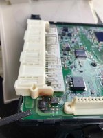
Well, finally got the issue resolved today. Ordered a used MPX/BCM from a junkyard for $75 plus shipping (made sure it was from an SR5 like mine) and the seller included the fuse box that it's mated to for free. The removal and install took about 45 minutes and all is well. Took apart the old MPX and sure enough, a singed circuit. Pics attached. Thanks to everyone for their help, and I'll be buying high quality led replacements and disconnecting the battery during install from now on.
 

Attachments

  • IMG_3865.jpg
    IMG_3865.jpg
    122.3 KB · Views: 969
Confirmed Mpx same part number for sr5 and limited

Yep, confirmed mxp has same part number for sr5 and limited but are programmed to function differently. Bought mpx from limited, installed and all is back to normal, plug and play.
Sr5 mpx for sale if anyone is in need of one.:D
 
Very interesting thread. Never would have thought that this could occur. Kinda scary!

Makes me wonder why this circuit is not tied in with a fuse!

BTW, I have been purchasing my LED replacement bulbs from SUPERBRIGHT LEDS for years and never had any issues.
 
Hi coreynw,

I hope I've read this post correctly... If your other door lights/Dome lights are working, you've gotta trace the driver-side door-light wire harness up as far as you can; there's likely a connector that's partially disconnected!

I have (Printed) most ALL of the wiring diagrams for any 4Runner year, but they're not in any file order. Since I used to store them all on "Photo-Bucket", and now they're holding them hostage, for a ransome fee, it makes them difficult to obtain QUICKLY!

So, try following the driver-side door light from the socket to the next wire connector; I seem to rmbr having that issue when I did my door-lock motor, when accidently letting go of the trim panel and losing power to the door lighting!

If that's not the trouble, I'll find the correct diagram, even if I have to go to "PB" and copy the url... even if it does have their "Water-mark" (Stain) on it, we'll still find the trouble, so don't worry, just let me know where we stand!

And thank you [MENTION=200736]ElectroBoy[/MENTION] for mentioning me in this thread, I'm honored to help out any way that I can! 'Best to you ALL'

rig, Happy New Year!

Hello, rigtec, I was hoping that you would be kind enough to send me all 5th gen electrical schematics. No worries if it’s too much a hassle.
 
Reinstalled original bcm and keyless entry functions are functional. Appears remote needs to be programmed to replacement bcm? I have techstream, any assistance would be greatly appreciated. :cheers:

Hi 06sport,

I have changed the MB-ECU due to a different issue and no need to re-program the key FOB; the key FOB (I think), is governed by the Certification ECU,

(Security system controller), e.g. door-locks, alarm system, "Engine Immobilizer"...etc! So if you replace a Certification ECU, then you can plan to update the key fob transmission code/frequency; but not for the MB-ECU!

BTW: The MB-ECU can be replaced in an hour and a half from start to finish! In an experimental effort to resolve a problem with a full instrument Cluster of warning lights "on at all times", and no speed-o-meter or Tach-o-meter,

I replaced the MB-ECU, but to no avail, so I ended up putting the original one back in so I could find the "REAL PROBLEM!" It turned out to be the YAW Rate acceleration calibration & Center point steering calibration causing the trouble!

So I bought a brand new MB-ECU only to put it back in the box to be used as an expensive paper weight/conversation piece, lol! Hope this post helps someone! 'Best to you ALL,

rig, Cheers!
 
Hello, rigtec, I was hoping that you would be kind enough to send me all 5th gen electrical schematics. No worries if it’s too much a hassle.

Hi The_Runner!

I don't think you wanna go through ALL of the 5'th Gen wiring diagrams cuz there are (easily), more than 1.000 pages in my "Printed" library...! I can get you the driver-door light scheme, but it'll have to be from photo-bucket (with the water-mark stain on it); and no telling what that stain would be covering up!

I'll be glad to look into it! Someone mentioned to me that they're using Whats-app to create a url for transferring photos/videos; maybe this is a perfect time for me to look into that!

If what-app works out properly, I'll be glad to load the driver-door prints to "Whats-app" and see if their urls can be loaded to this page or in a PM for you to use... I'll look into that!

rig, cheers!
 
Hello, rigtec, I was hoping that you would be kind enough to send me all 5th gen electrical schematics. No worries if it’s too much a hassle.

Hi The_Runner,

I've been going through the Courtesy Lamp Circuit regarding the D/S Door Courtesy light circuit and here's what I think would help you to isolate your problem! The "Left front door courtesy Lamp circuit" Begins & ends at the MB-ECU terminals FLCY(+) & FLCY(-)!

So to be sure what the trouble is, I would (using a test light or 12V Multi-meter), GND the alligator clip/NEG-side of your tester, and touch the copper terminal attached to the "PINK" wire and see if it's HOT; it should be whenever the driver-side door is opened!

Then, I'd check the terminal attached to the RED wire (GND-TERM) by feeding the alligator clip 12V (from another power source), and connecting the test lead to that copper terminal; you 'SHOULD' have 12V at that termination!

If you don't have 12V (GND) at the RED wire, then check the door courtesy light switch; this is where your MB-ECU courtesy signaling device is located. You could remove the door switch and use an Ohm meter or continuity tester to confirm, or condemn the door switch BEFORE Condemning the MB-ECU!

Obviously I do have the wiring diagram for the door lamps; my trouble is getting a url to share them as photos/jpeg. If you need to see them for yourself, send me a PM with your email address and I can email the two pgs to you!

And if you need to replace the MB-ECU Compu net, I do have a Brand New one, from Toyota, still in the original box... just let me know how you make out AFTER testing the door lamp courtesy circuit and we can take it from there! 'Best to you'

rig
 
Can someone confirm this for me please.

I want to replace the courtesy door lights with LED bulbs from Diode Dynamics. But after reading a few on these posts I'm all worried now. Just would like some confirmation on the guys that have done this before and if my method here will be a safe method.

1. disconnect negative terminal of battery

2. remove courtesy light housing from door panel for full access

3. remove incandescent bulb and replace with LED bulb

4. install courtesy light housing back in to door panel

5. connect negative terminal of battery


Is this method OK? I don't have a multimeter nor the motivation to buy one and read/learn how to understand it just to pop some new bulbs in right now. Too much other stuff going on currently. Also don't have any idea or motivation to figure how to hook one of these bulbs up to a 9v battery to test either. I'm not normally this consumed with other things but here we are. I'm just looking for some quick intel before buying these this morning.

Do these bulbs need to be installed a certain way regarding polarity? If I install them backwards will anything bad happen or will the light just not work? And if thats the case I would just disconnect the negative battery terminal, repeat the earlier procedure and flip the bulb 180 degrees?

thanks for reading my rambling post.
 
Hi - I did this recently with the same concerns (I'm a real worrier) and have a few pieces of advice.

1) Skip DD. Use VLEDS. The quality is better and the polarity doesn't matter like they do on DD. They also have a better choice of color temperature. Finally, you can get them on Amazon with free shipping and free returns if you decide to try another color.

2) Do the 9V battery. It's easy. Step 1 buy a 9V battery. Step 2 put one end of the VLEDS bulb on the negative terminal, tilt it sideways, and you will hit another spot on the bulb and it lights up. Easiest part of any of this.

3) Read this. Makes the door (hassle) easier.

This may start an "internet war" but I didn't remove the negative terminal. If the bulb is going to cause problems, it will happen as soon as electricity is applied, so it was far more important IMO to test the bulb before inserting.

Good luck.


Can someone confirm this for me please.

I want to replace the courtesy door lights with LED bulbs from Diode Dynamics. But after reading a few on these posts I'm all worried now. Just would like some confirmation on the guys that have done this before and if my method here will be a safe method.

1. disconnect negative terminal of battery

2. remove courtesy light housing from door panel for full access

3. remove incandescent bulb and replace with LED bulb

4. install courtesy light housing back in to door panel

5. connect negative terminal of battery


Is this method OK? I don't have a multimeter nor the motivation to buy one and read/learn how to understand it just to pop some new bulbs in right now. Too much other stuff going on currently. Also don't have any idea or motivation to figure how to hook one of these bulbs up to a 9v battery to test either. I'm not normally this consumed with other things but here we are. I'm just looking for some quick intel before buying these this morning.

Do these bulbs need to be installed a certain way regarding polarity? If I install them backwards will anything bad happen or will the light just not work? And if thats the case I would just disconnect the negative battery terminal, repeat the earlier procedure and flip the bulb 180 degrees?

thanks for reading my rambling post.
 
Hi - I did this recently with the same concerns (I'm a real worrier) and have a few pieces of advice.

1) Skip DD. Use VLEDS. The quality is better and the polarity doesn't matter like they do on DD. They also have a better choice of color temperature. Finally, you can get them on Amazon with free shipping and free returns if you decide to try another color.

2) Do the 9V battery. It's easy. Step 1 buy a 9V battery. Step 2 put one end of the VLEDS bulb on the negative terminal, tilt it sideways, and you will hit another spot on the bulb and it lights up. Easiest part of any of this.

3) Read this. Makes the door (hassle) easier.

This may start an "internet war" but I didn't remove the negative terminal. If the bulb is going to cause problems, it will happen as soon as electricity is applied, so it was far more important IMO to test the bulb before inserting.

Good luck.

Yeah, good advice. Please don’t skip the LED test. A shorted LED right out of the package is a main cause of this type of ECU failure that have been reported in forums.

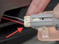
By unplugging the white power connector on the back of the courtesy light you effectively remove power from it and really don’t need to remove the battery negative terminal while replacing this bulb.
 

Attachments

  • 16931846-40AD-41CB-86F4-0A100B915CD6.jpeg
    16931846-40AD-41CB-86F4-0A100B915CD6.jpeg
    26.1 KB · Views: 456

Members online

Forum statistics

Threads
278,315
Messages
3,554,104
Members
248,016
Latest member
Advally Service

Trending content

Back
Top