enginerd4ni's build thread

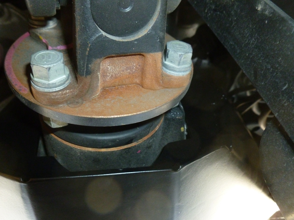
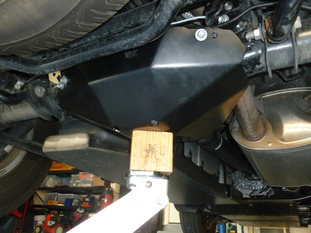
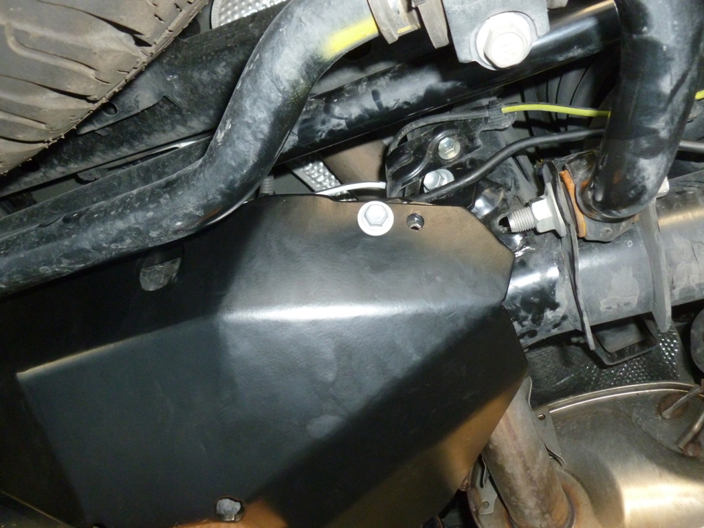
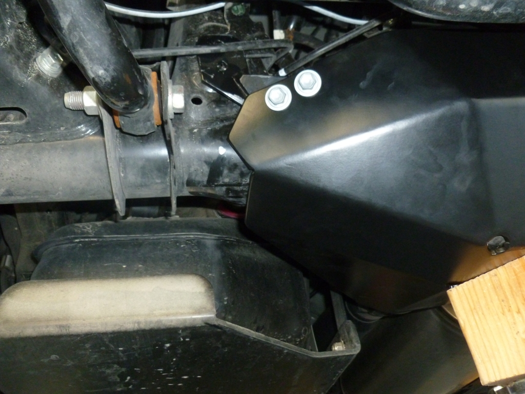
The gap on the driver side is a little over 3/8" and the gap on the passenger side is a little over 1/4". To me, that is close enough given the crazy tolerance stack up. Just to be worst case, I jacked the driver side up using a hi-lift on the outer tube of the slider. I can't think of any real world use cases where I would need to access the rear door while being only supported by the jack or a giant rock, but my engineering curiosity got the better of me.

http://www.automotivating.com/forum/pics/slider26.jpg[/IMG

I only jacked it up until the wheels were starting to squeak loose. The door still opens barely on the driver side but I might not be as lucky on the passenger side which sits a bit lower or if I keep jacking sky high. Here is a close up of the driver side gap.

[IMG]http://www.automotivating.com/forum/pics/slider25.jpg[/IMG

My opinion is job well done by Bud.

I hope this helps.[/QUOTE]

Wow, thank you VERY MUCH! This is exactly the information I was looking for :)

My gap variance is roughly the same when I measured it a long time ago, which seems to be within tolerance in the grand scheme of things. It didn't really bother me at all, but I have to admit I was always curious. It's good to know that it's "normal", so to speak. I knew it would an engineer to answer an engineer's question in a satisfactory manner, lol. Anyway, thanks again, the info is much appreciated!
 
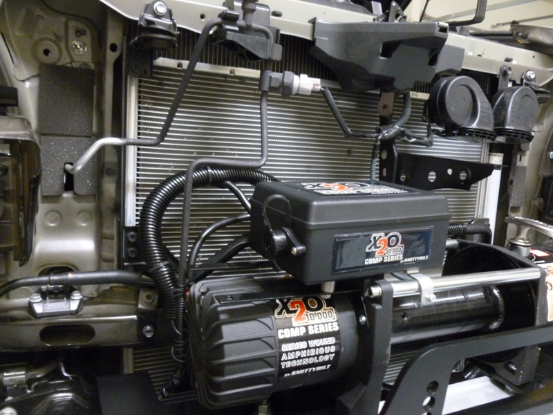
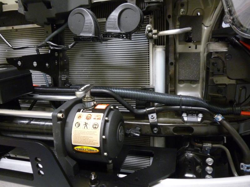
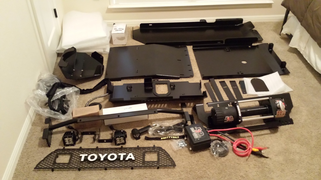
Bud Built Hidden Winch Plate + Smittybilt X20 10K Comp

I'm finally getting around to writing up the install which I completed last November!

Parts:
Bud Built Hidden Winch Plate 21.8 lbs
Smittybilt X20 10K Comp (Synthetic) 43.6 lbs + 15.6 lbs for the solenoid/wiring, synthetic line, hook, fairlead

Reason for install:
A winch is an integral part of an overlanding vehicles ability to self recover when out in the middle of nowhere. For the 5th gen, the options seem to be going full bore with a front winch bumper, going stealth with a hidden winch plate, or going versatile with a front hitch receiver mount setup. There are pros and cons to each setup. For me, I wanted to go for the stealth look which gives me the capability of a fully functional winch bolted to the frame but without the substantial weight and visual impact of a winch bumper. The front bumper of the Trail edition offers reasonable approach angle and maintains the stock appearance to not attract too much attention. If I hit a dear or substantially scuff up/tear off my bumper, then I'll probably replace it with a winch bumper and hopefully someone will have a nice aluminum bumper that meets my aesthetic needs by then. For now, the hidden winch plate is the right mix of stealth, weight, and price.

For the winch, there is an overwhelming amount of options out there. I don't plan on regularly using the winch but when I do, it needs to work and not be all rusted out. I am also trying to limit the amount of weight that I add in keeping with the purpose of the build. I settled on the Smittybilt X20 10K Comp for several reasons. It is fully submersible/waterproof which means I shouldn't have to worry about the guts getting rusted out. It has just enough pulling power sized for my rig. It has a weight saving synthetic line and aluminum hawse fairlead which offers a safer operation (limited/no potential energy storage and no burrs/splinters) and allows me to keep a spare line with minimal extra weight. It has a remote mountable solenoid which is critical for using the hidden winch plate and many winch bumpers. It offers a lifetime mechanical warranty. It was quite affordable. The downsides are that it is made in China (looks like the same factory that makes the Harbor Freight Badlands winches) and the build quality is a little questionable. When I took it out of the box, I had to tighten all of the electrical connections to ensure that they would remain waterproof. There were also burrs on the spool that could have damaged the synthetic line which I had to file off. All in all, I'm quite happy with it though I have not yet had to put it to the test. I'll report back.

So now, on to the pictures of the install!

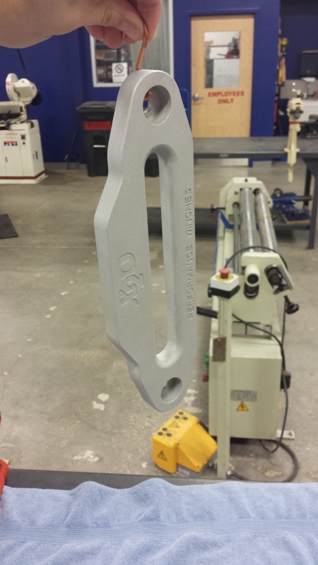
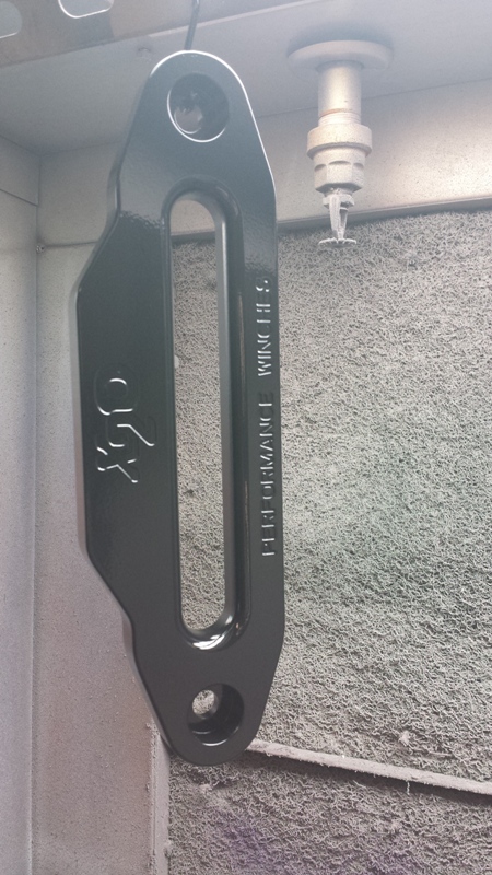
I started with the hawse fairlead. It came with a nice anodized finish but I prefer a blacked out look coming from the bumper so off to Tech Shop to powder coat it with the same powder Bud Built uses on the winch plate.
winch01.jpg

winch02.jpg


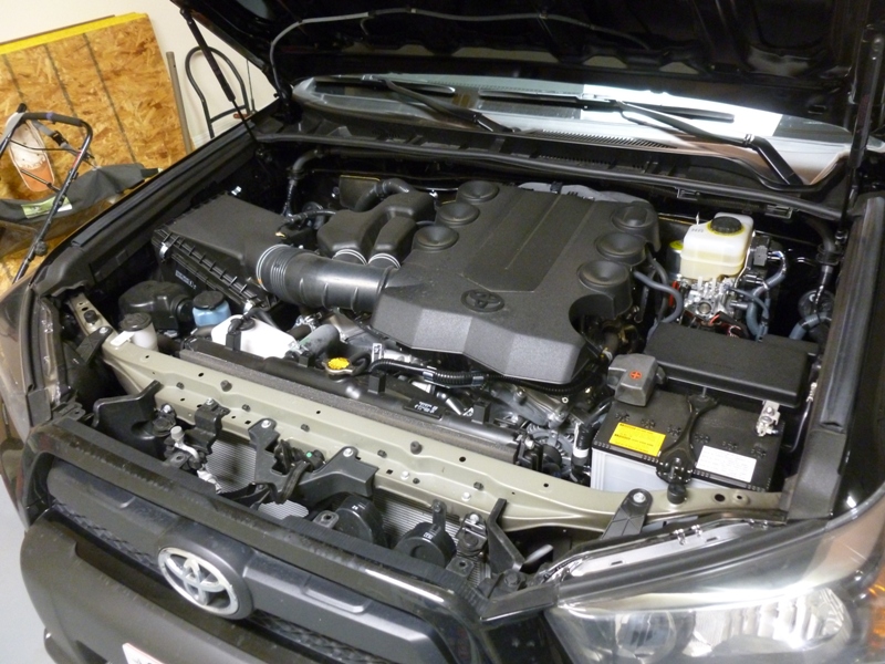
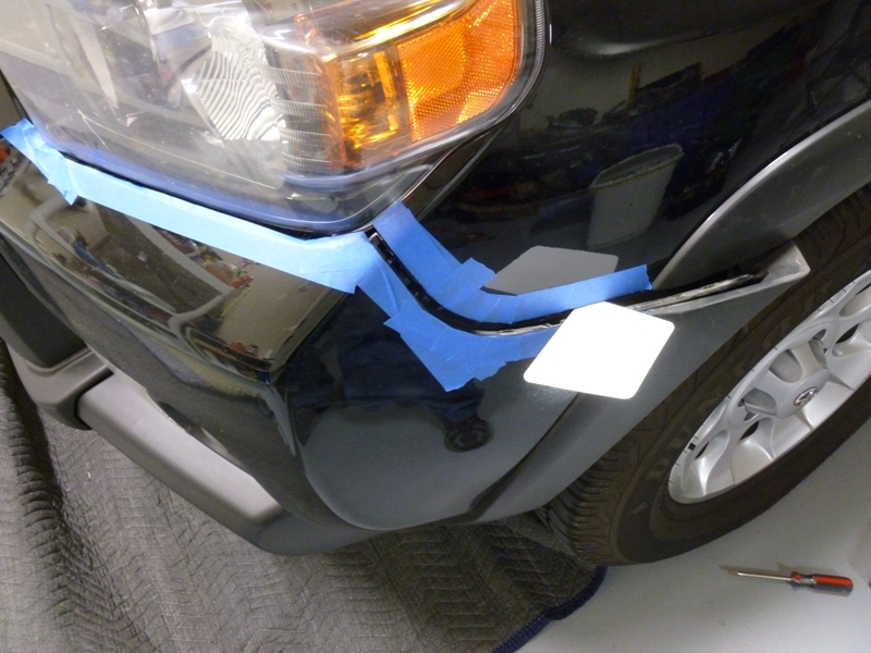
Now to take off the front bumper cover. Remove the radiator cover plastic.
winch04.jpg

winch05.jpg


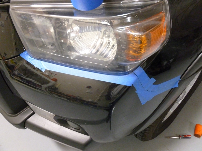
Remove the bolts from inside the fender / wheel well along with all of the bumper cover bolts underneath. Carefully pop out the retaining clip hold downs by pulling the side of the bumper cover from the wheel well out and forward. There is probably a better write up on how to do this, so search for it!
winch06.jpg

winch07.jpg


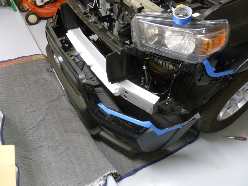
Slide the bumper cover forward enough to disconnect the fog light harnesses and then pull off and lay onto a large blanket to protect the paint. It may want to roll forward so be careful.
winch08.jpg


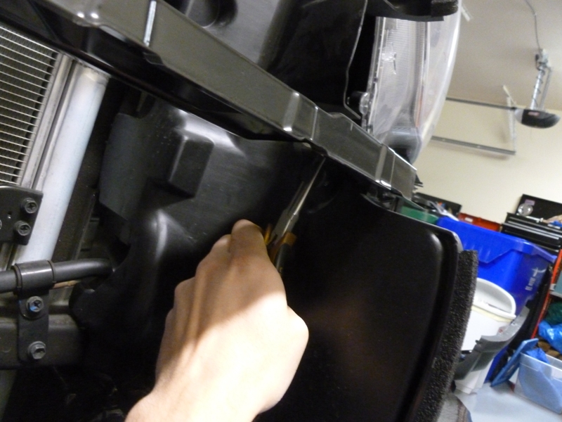
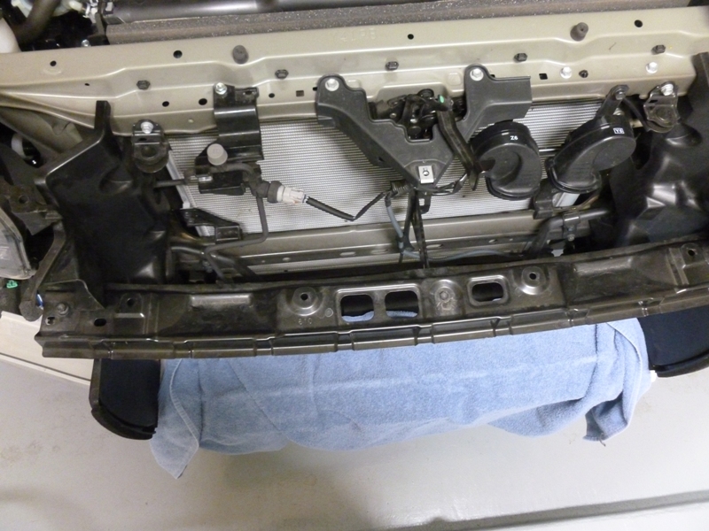
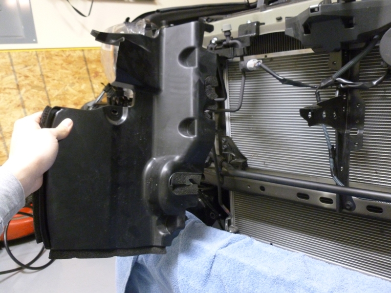
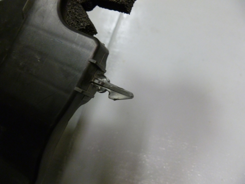
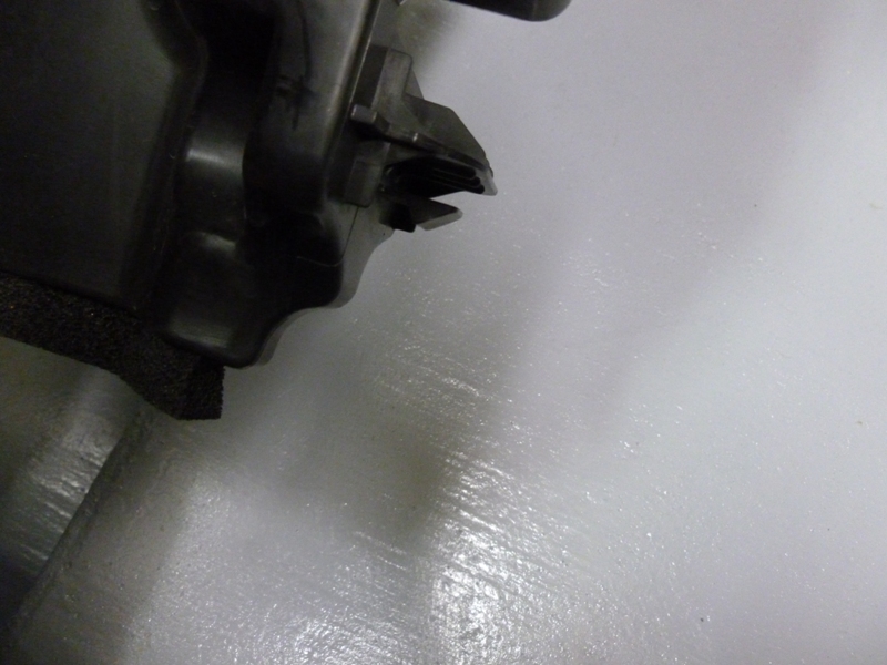
Remove the plastic air dams and the grille support brace, they have some clips that need a little persuasion.
winch10.jpg

winch11.jpg

winch12.jpg

winch13.jpg

winch14.jpg


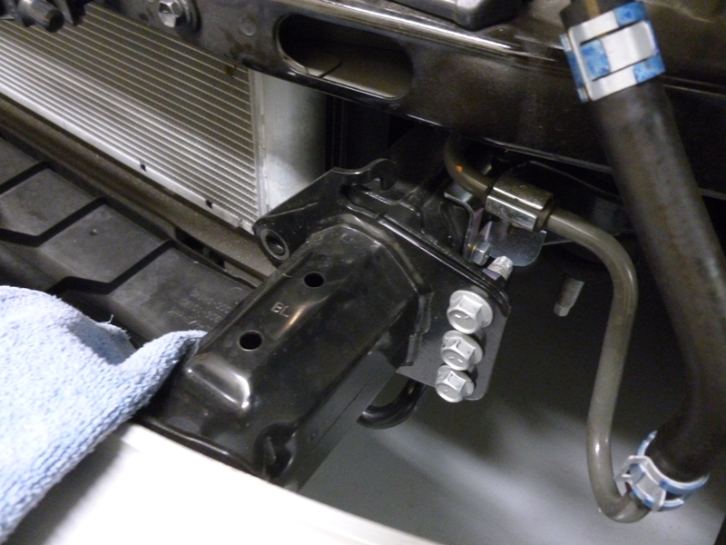
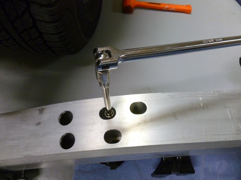
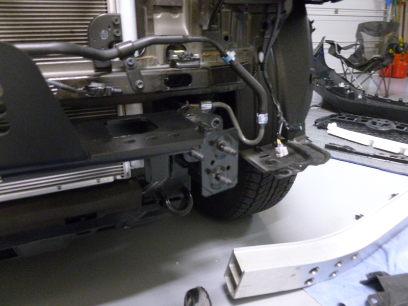
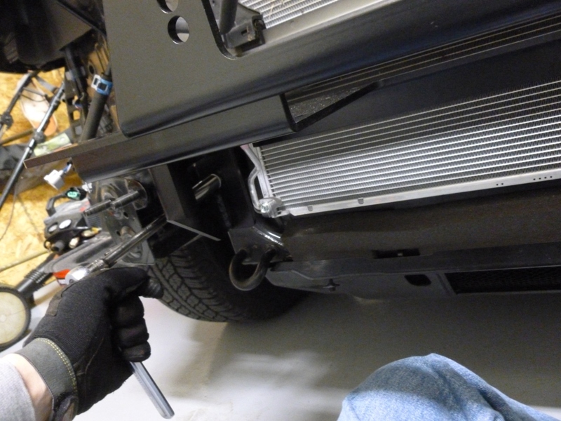
At this point, you may want to consider removing the aluminum bumper from the brackets and leaving the brackets loosely installed to the frame rails with only the outermost bolts. You'll see why later and this may make it easier for you to remove the brackets. You can do this by accessing the bolts directly from the front holes in the bumper after removing the styrofoam insert.

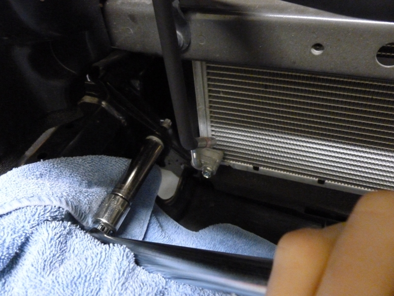
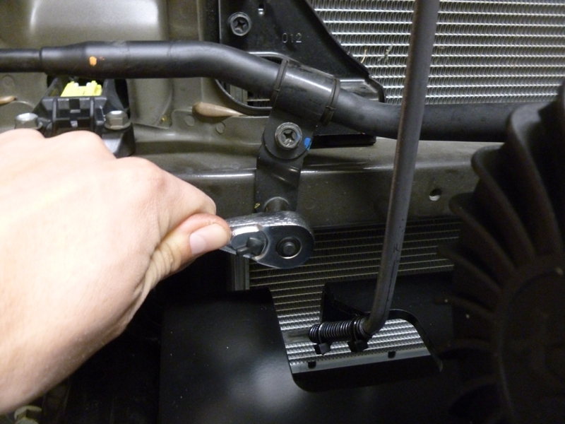
Start removing the bolts that attach the bumper to the frame rail.
winch09.jpg

winch15.jpg


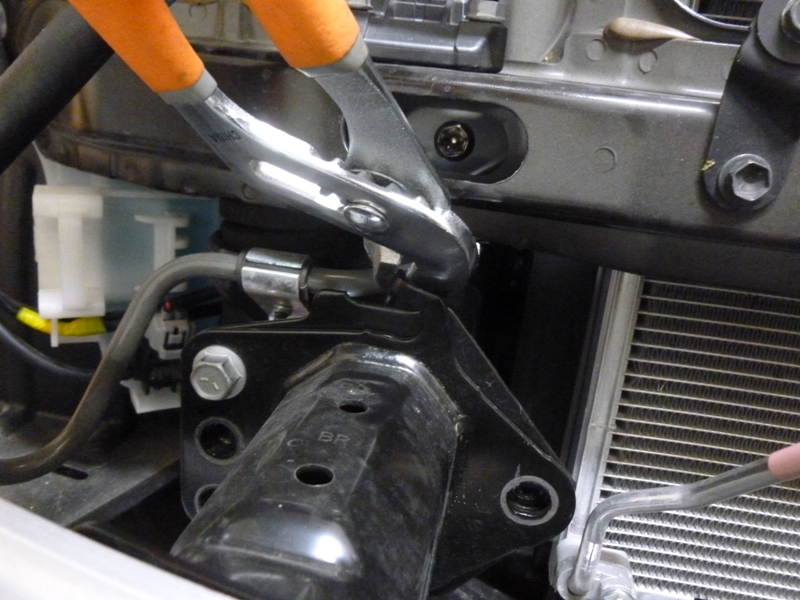
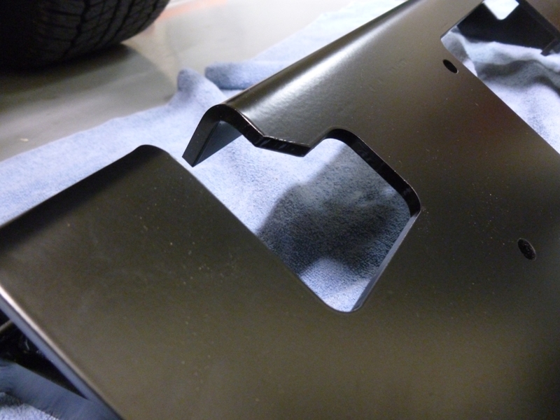
You can optionally bend the tab so the bracket doesn't try to catch when removing the bumper.
winch16.jpg


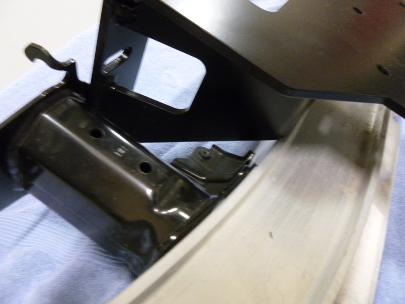
As you can see, the winch plate doesn't fit exactly. This is why I suggest removing the aluminum bumper or at least loosening it to sandwich in the winch plate.
winch17.jpg

winch18.jpg


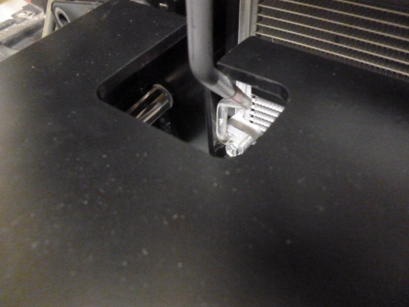
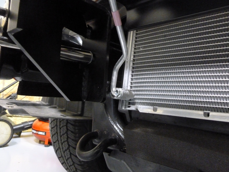
I had to saw off a corner of the bracket to allow the air conditioning line to pass through without rubbing.
winch20.jpg

winch20d.jpg


Continued...
 
Hidden Winch Mount Continued

Now install the winch plate just in front of the bumper to frame rail brackets and tighten up all the bracket bolts.
winch19.jpg

winch21.jpg

winch22.jpg


I had to flip some of the brackets for this line because it was rubbing the back of the winch.
winch23.jpg


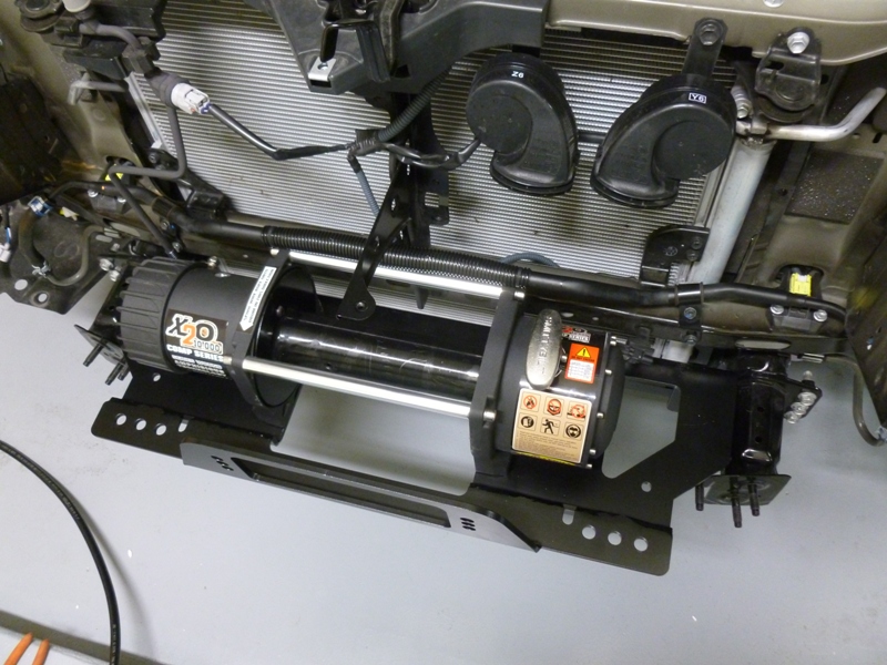
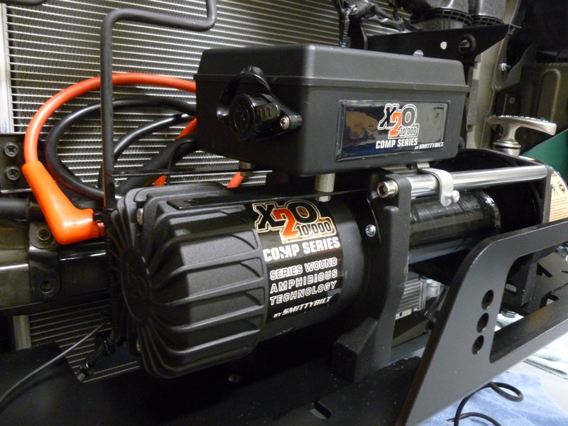
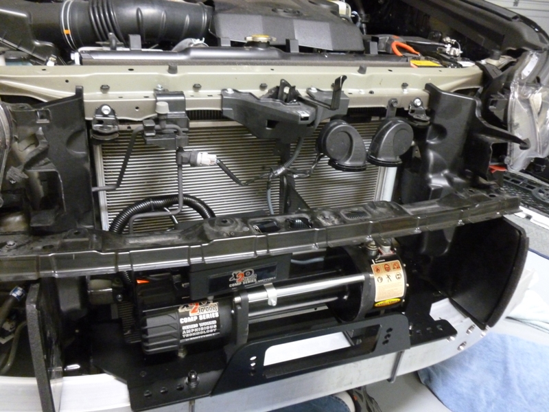
Now for test fitting the winch.
winch24.jpg


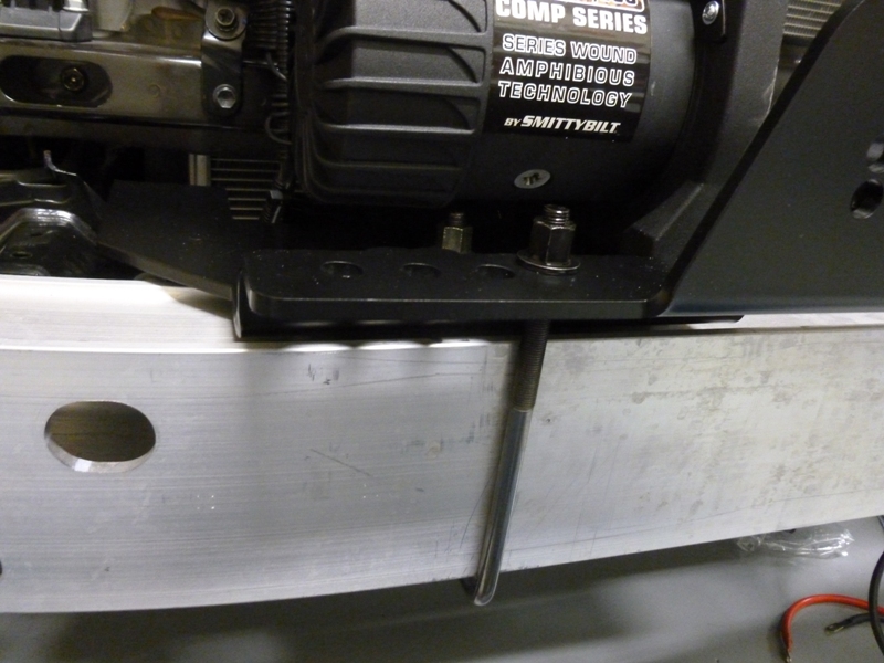
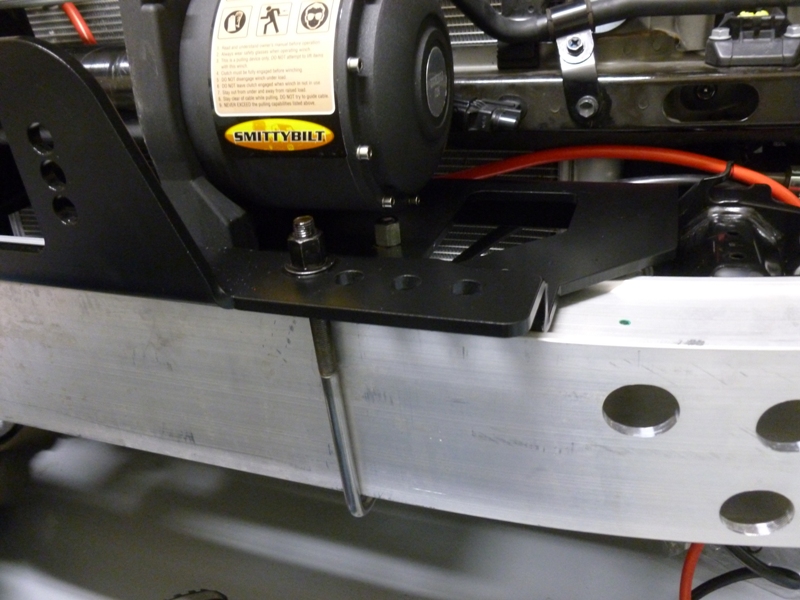
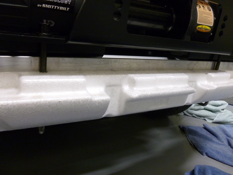
The u-bolts secure the winch plate to the aluminum bumper. I had to trim the end off of one side of the driver side u-bolt so it would clear the gearbox.
winch29.jpg

winch29b.jpg


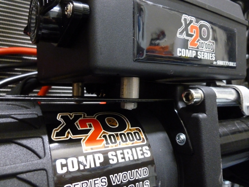
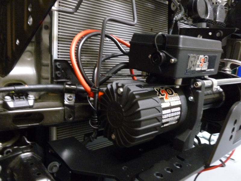
I had to rig the location of the solenoid to be halfway between the the motor and the spool. This location doesn't interfere with the grille support bracket or the air dam but also allows enough access to the control connector. I used some aluminum spacers I had laying around and the brackets that came with the kit.
winch25.jpg

winch26.jpg


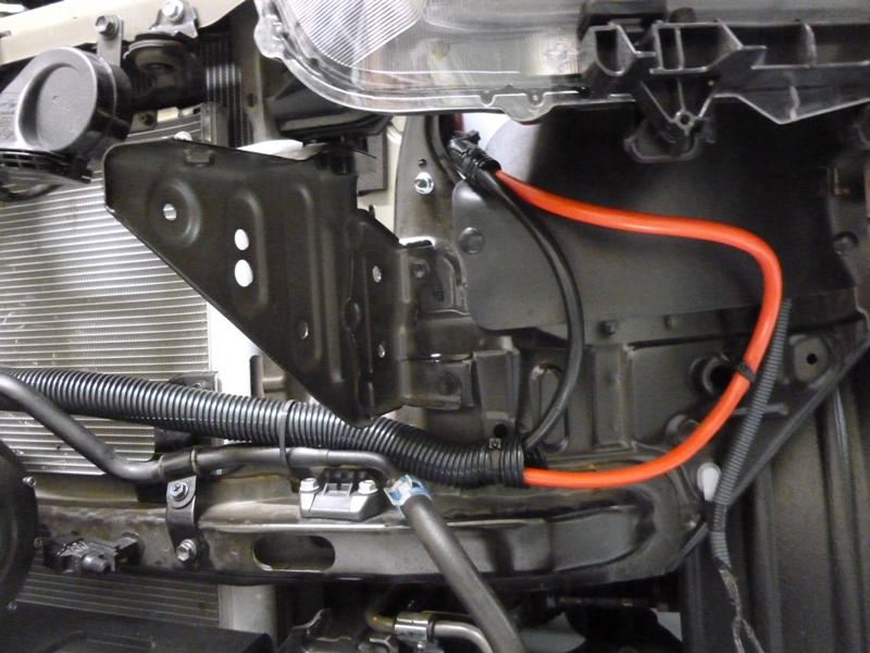
Now to reattach the bracket for the line running behind the winch and start wiring and wrapping.
winch27.jpg

winch28.jpg

winch30.jpg

winch31.jpg


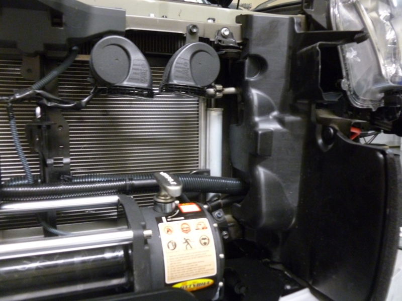
Putting the air dams and grille support brace back on.
winch33.jpg

winch34.jpg


I carved out a little bit of the back of the foam insert to make room for the u-bolts.
winch35.jpg


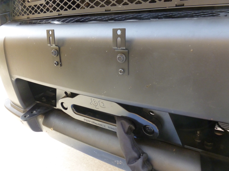
I happened to have these brackets lying around so I used them to bring the license plate up to clear the winch line. I then installed a plastic license plate bezel to complete the look. If I'm in a really crazy recovery situation and the line gets anywhere close to the license plate, I'll just remove it.
winch36.jpg


I also ordered the optional light brackets from Bud Built. While I had the bumper apart, I wired an extra set of power and ground to eventually install a set of lights on the brackets.

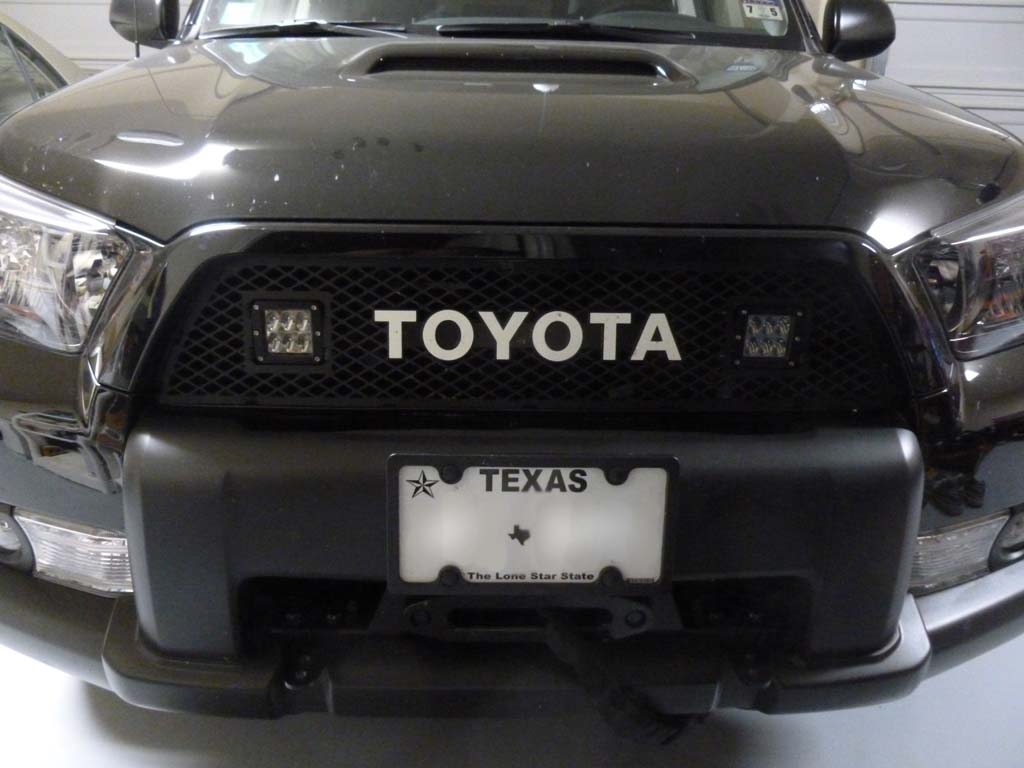
Here's the final look, sorry for the dirty vehicle and poor lighting!
winch37.jpg


I don't have any pictures of installing the synthetic line but it is pretty straight forward:
-attach the fixed end of the line to the small screw on the side of the spool.
-plug in the remote control and wind in the line

Since it is best to wind in the line under a few hundred pounds of tension, I used the following procedure:
-Find something very stable and not going anywhere such as a large tree, a concrete light post base in a parking lot, a parked truck with the parking brake on, etc.
-Attach the free end of the line (attach hook to tree saver or recovery point)
-Spool out or back up until the spool is covered by only one wrap (layer) of line
-Make sure to position yourself downhill from the stable object if possible or use your parking brake just slightly (I used about 3-4 clicks) to provide the tension
-Using a buddy, start spooling in the line while you watch the feed. When the feed reaches near the side of the spool, have your buddy cut the wheel toward that side so that the feed starts winding toward the opposite side without bunching up on that side
-Feed in until you about reach the end and use proper safe winching technique to feed in the last bit without pinching your fingers.

Other than that, every month or so, put the clutch into neutral and free spin the winch to keep it lubed inside.
 
Bud Built Aluminum Skids and Steel Diff Skid

Parts
Bud Built Aluminum Skid Plates
Bud Built Steel Diff Skid
Front Skid: 12 lbs
Mid (Transmission) Skid: 19.2 lbs
Rear (Transfer) Skid: 17.6 lbs
Cross Member: 15.6 lbs (Steel)
Gas Tank Skid: 28.6 lbs
Diff Skid: 16.8 lbs (Steel)
Optional: Diff breather relocation
Optional: Fumoto Quickvalve

Reason for Install
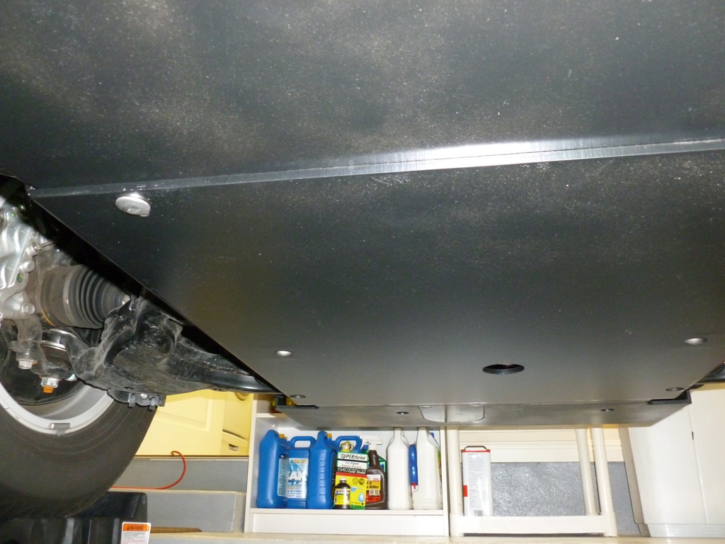
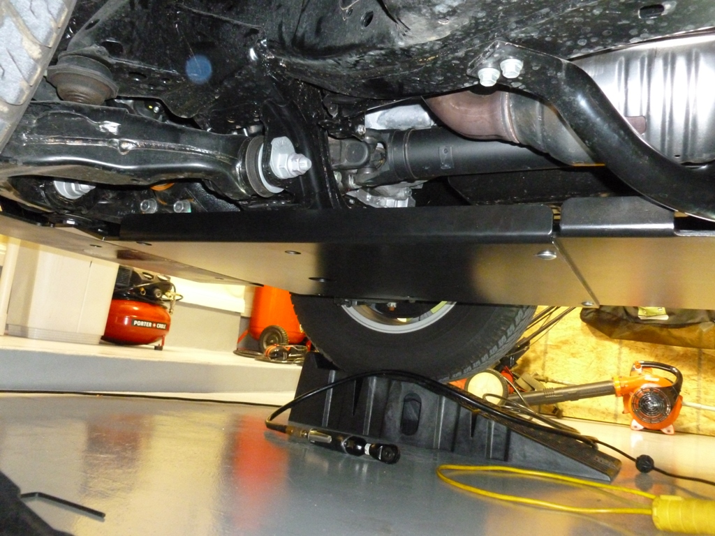
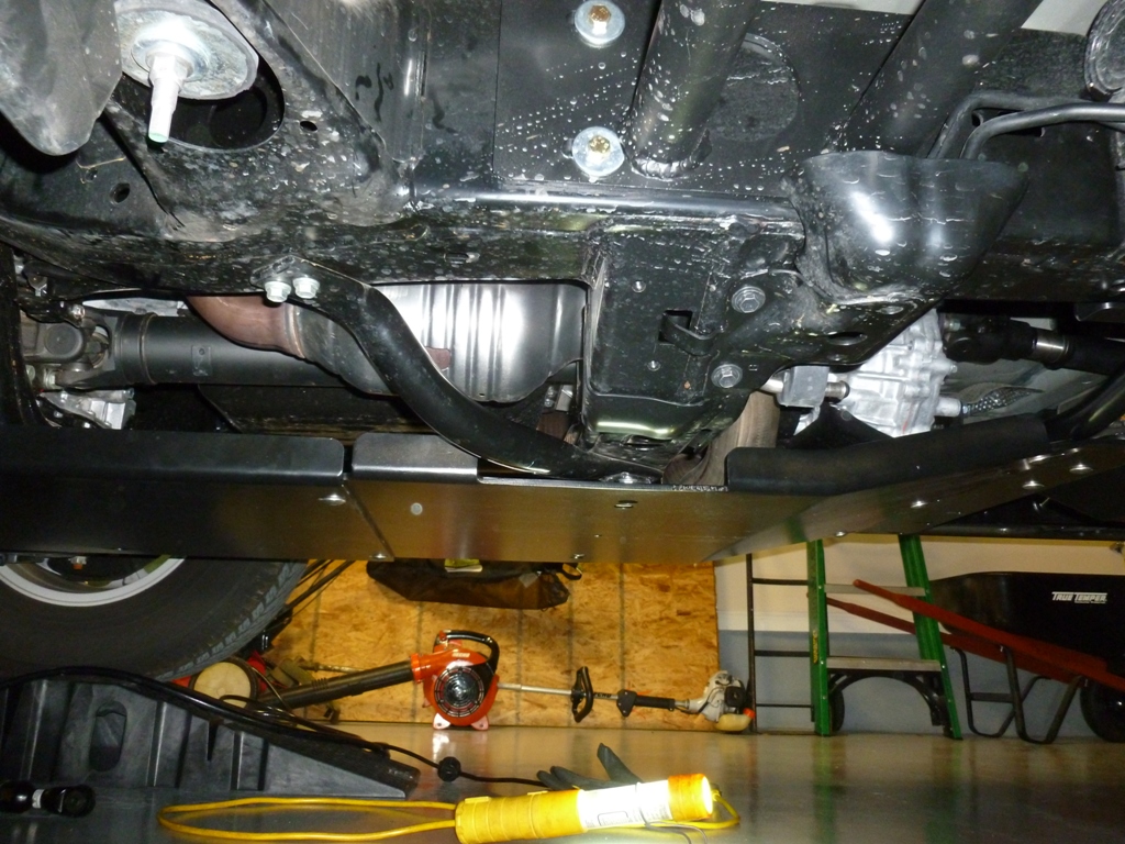
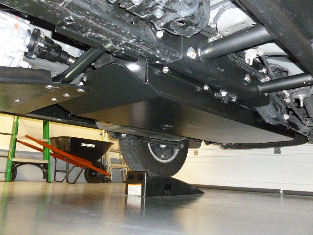
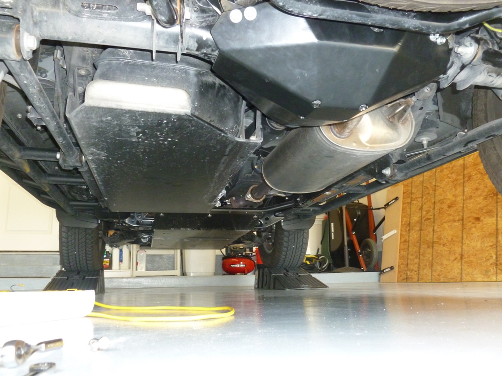
The factory skids are pretty weak in my opinion and only marginally protect the oil pan and gas tank while leaving the transmission, transfer case, and differential exposed. I'm not expecting to do hard core rock crawling every weekend. Rather, if I find myself on a trail in the middle of nowhere that is a little more than the 4Runner can handle, I will have peace of mind knowing I won't be trashing the vital bits in between the frame rails if I take the wrong line, slip, etc. Similar to the sliders, full underbody skids help prevent vehicle damage but skids in particular can make the difference between "huh, guess I misjudged that ledge, anyway" and "I wonder if my triple A towing coverage works in Patagonia". I chose aluminum because it saves valuable weight and is less affected by corrosion. Bud's 5-piece skid plate combo in steel weighs 200 lbs whereas the aluminum version comes in at 93 lbs. I threw in the diff skid for good measure and extra protection especially if I'm on a trail with ruts.

This post won't be a step by step installation instruction as the install is pretty straight forward. Rather, I will just show some pictures that I thought might be useful and point out some things that weren't so obvious.

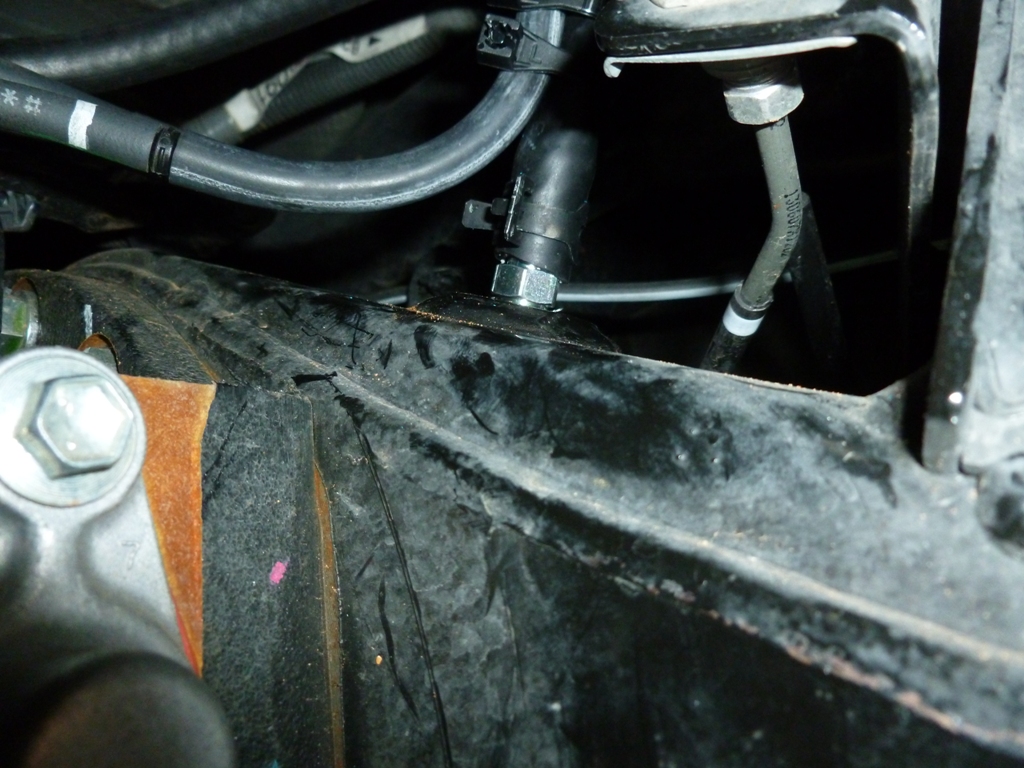
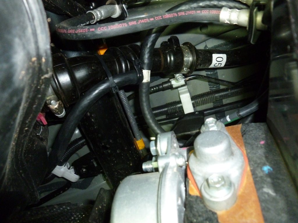
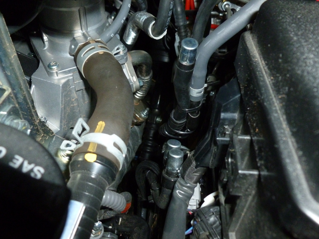
The very first thing I did was relocate the diff and e-locker breathers to the front engine compartment. There are some other good write-ups on this forum with good ideas. I decided to splice the two into one line that runs along the frame rail and then up around on the driver's side of the engine bay and sits next to the breathers from the transfer and front diff. The e-locker already has a hose and tube that extends the location of the one-way valve a little bit higher. I just re-routed that hose into the new line coming from the diff housing. The one way on the diff housing simply unthreads and can be replaced with a barb fitting. You only need one but here is a pic of the threaded barb and the barbed breather. Eventually I will probably replace all of the one way breathers with a manifold and filter breather.
skid10.JPG

skid09.JPG

skid08.JPG

Courtesy of EHNWI
axVk5V6l.jpg


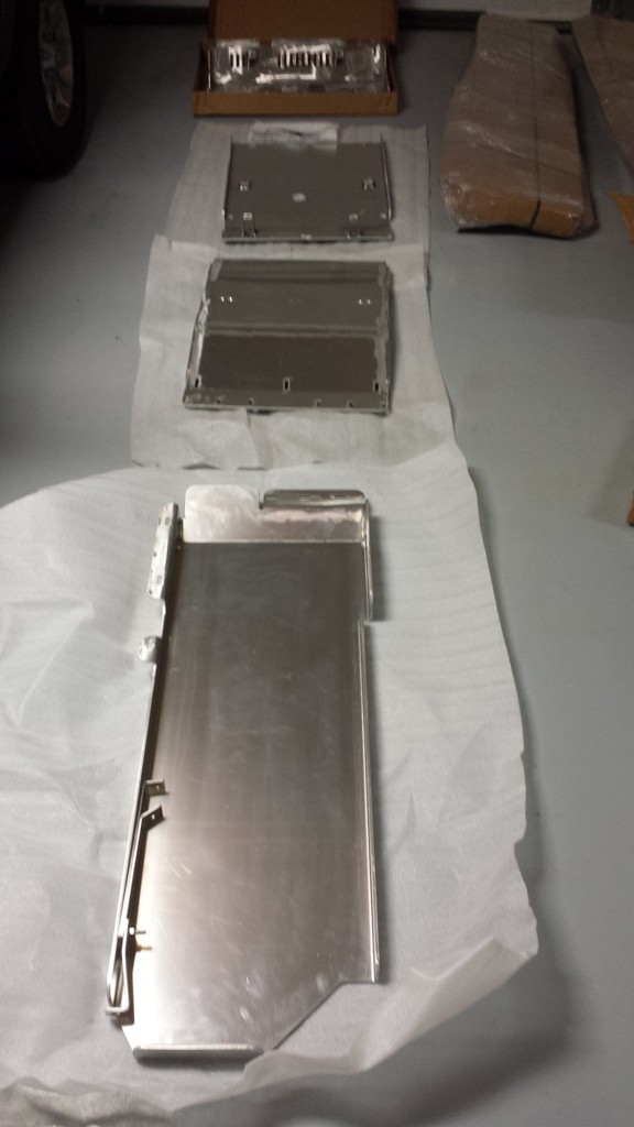
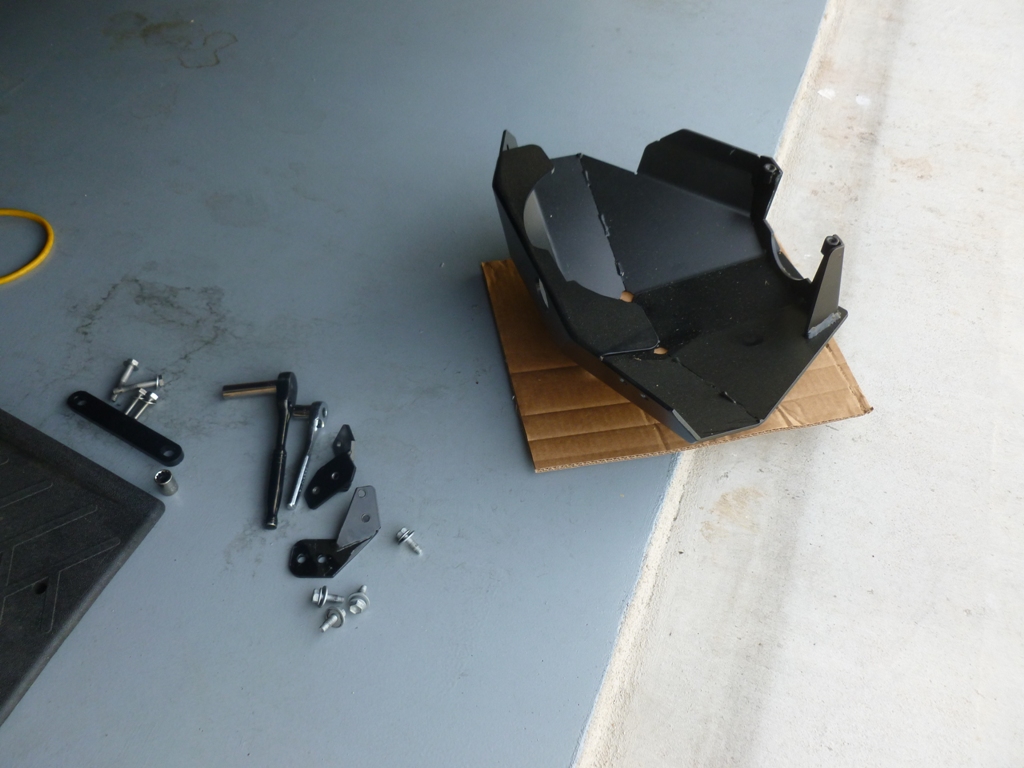
Here are the unboxed skids.
skid01.jpg


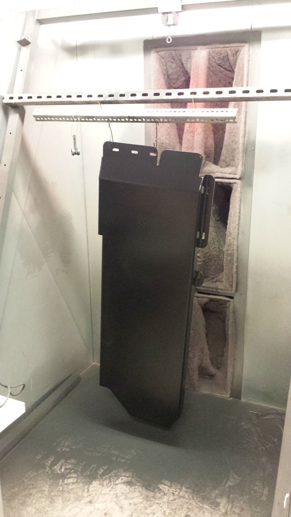
Powder coating them at Tech Shop. Getting these parts in and out of the 400°C oven made me glad they were aluminum!
skid02.jpg

skid03.jpg


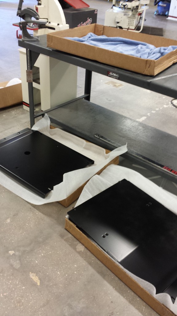
Ready to install
skid04.jpg


Tip:
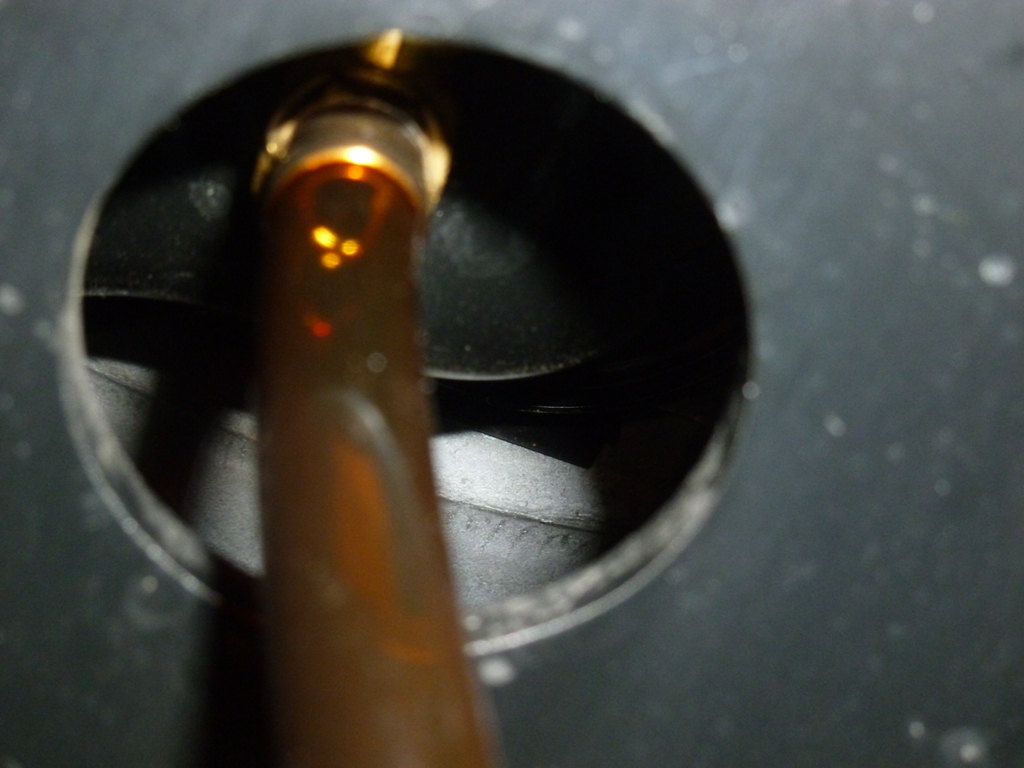
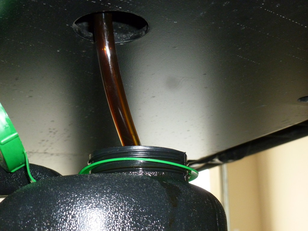
Install a Fumoto Quickvalve in place of the oil drain plug. Of course this means draining your oil but future oil changes are a breeze and very clean without having to remove any of the skid plates or making a mess. (The cartridge filter is a whole other story though)
oil01.JPG

oil02.JPG


Tip:
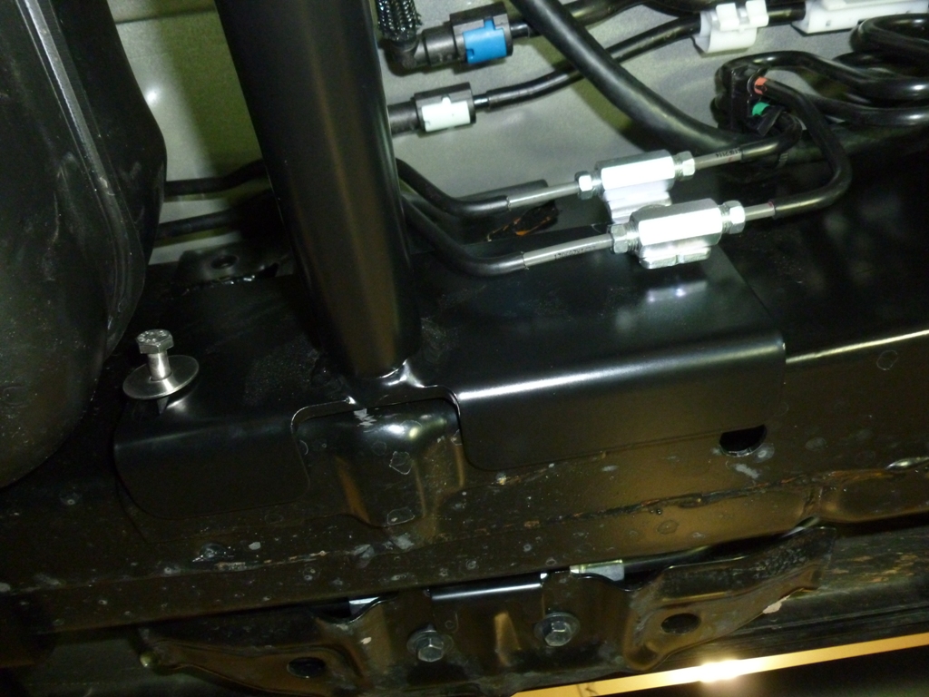
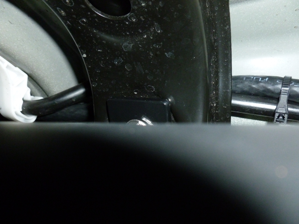
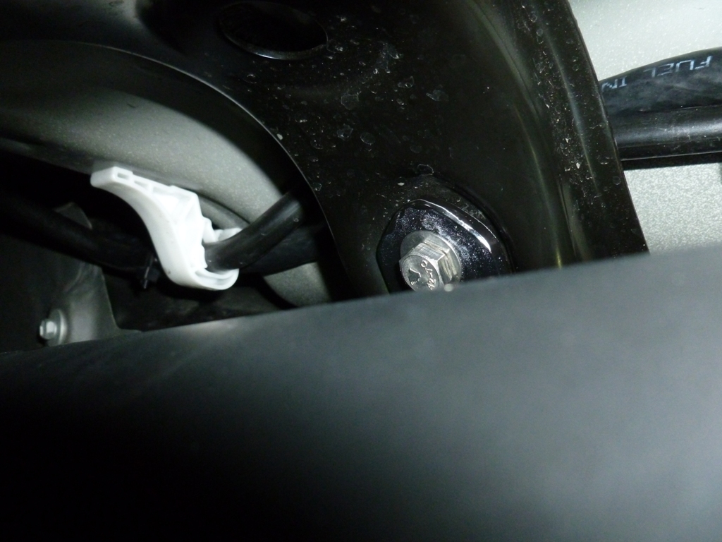
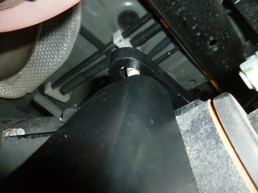
The support brace snuggly fits in between the frame rails and some brake line brackets will need to be re-secured on top of the bracket. If you have KDSS, 1/4-20 bolt shown on the left of the picture below may not be long enough. I had to buy a 5" bolt. Also, don't install it in the direction shown!
skid11a.JPG

Instead, remove the KDSS shield and the bracket bolt and insert the 5" 1/4-20 bolt from the outside with the nut near the gas tank. You will not use the KDSS bracket bolt that you removed. The 1/4-20 bolt is skinny enough to pass through the threads of the M8 weld nut on the frame rail.
skid11b.JPG


Tip:
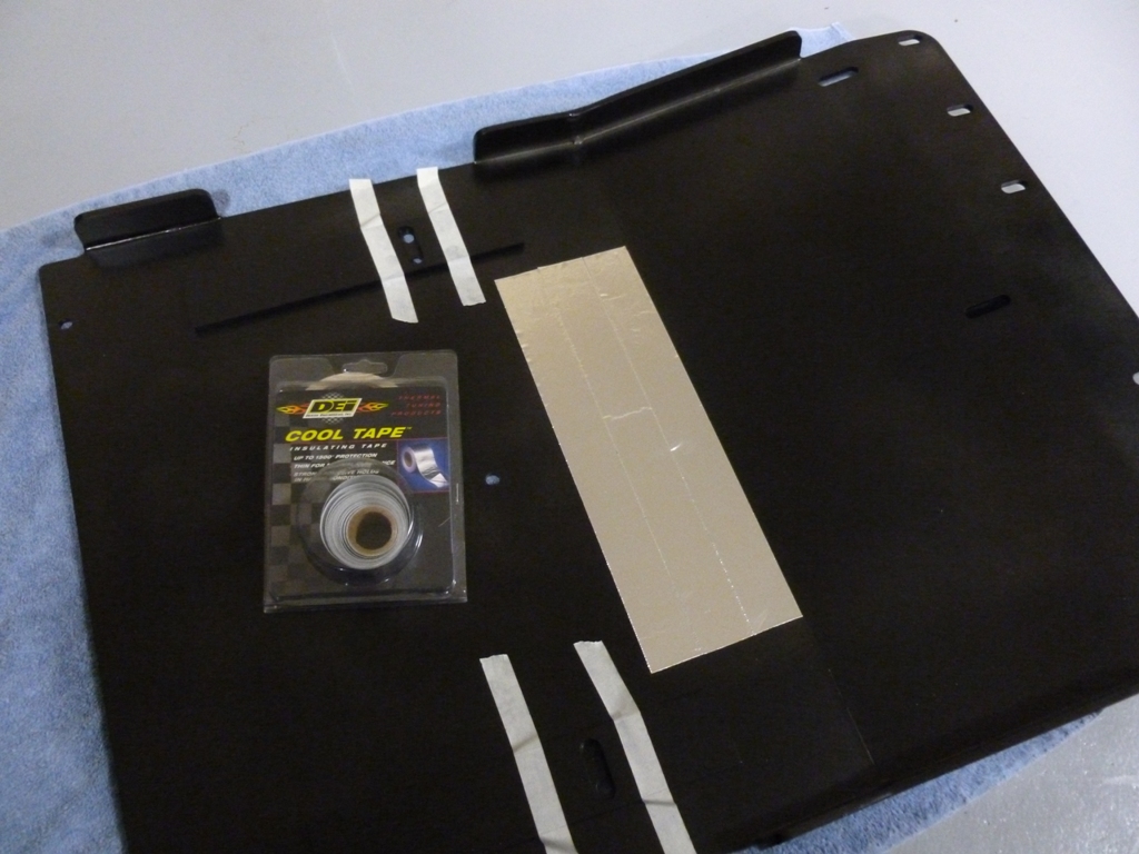
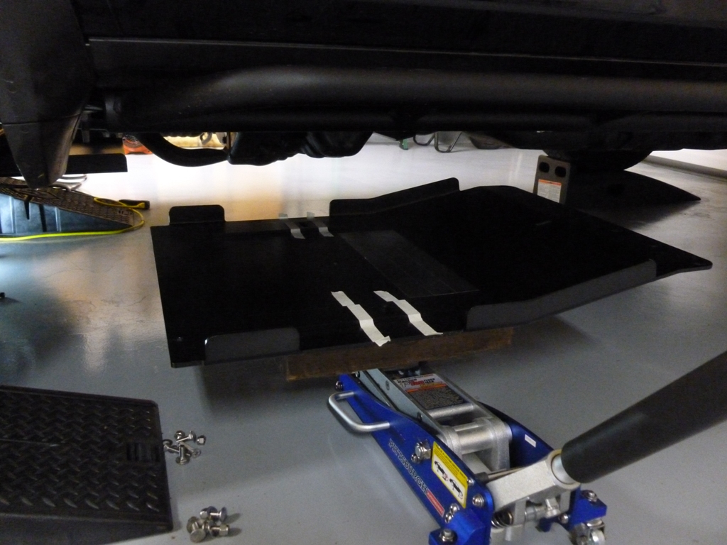
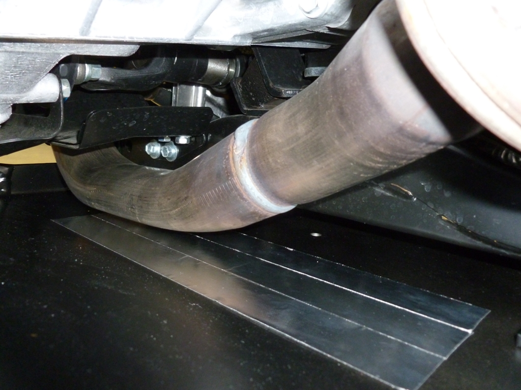
Tape the metal braces/spacers (bracers?) to keep them from moving around while you are trying to raise the skid into position and get it bolted up. Then use a floor jack to support the skid while you get it all lined up and bolted in. (optional) I had some insulating tape laying around so I put some on the top side of the rear skid where the exhaust pipe runs close to the skid. I didn't place it in exactly the right spot unfortunately. If you do this, move it closer to the driver's side.
skid12a.JPG

skid12b.JPG

skid12c.JPG


Tip:
The gas tank skid bracket doesn't sit inside the curved recessed portion of the stamped panel. I rounded off the corners of the bracket and touched up with black nail polish.
skid13a.JPG

skid13b.JPG


Observation:
The slots in the skids allow for some misalignment but I was pretty much at the limits of the slots for each panel.
skid14a.JPG

Continued...
 
Bud Built Skids Continued...

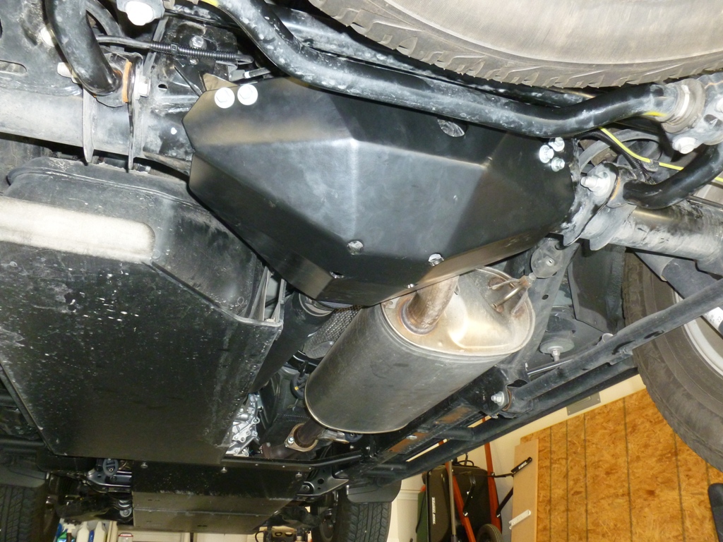
Views of the installed skids:
skid14c.JPG

skid14b.JPG

skid14d.JPG


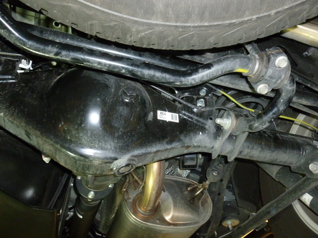
Diff Skid Before:
skid15a.JPG


Tip:
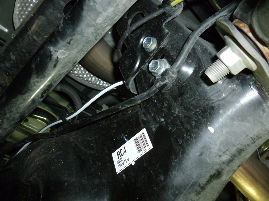
Move this bracket to the bolt just above it.
skid15b.JPG


Tip:
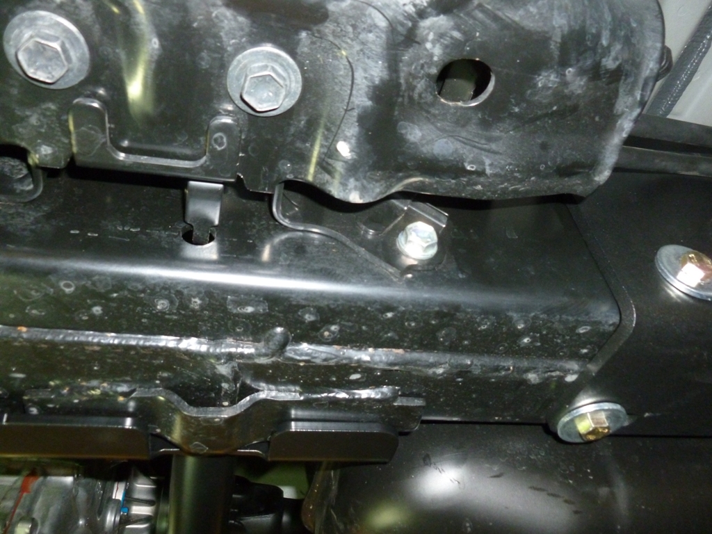
Remove this bolt but keep the brake line bracket in place and underneath your diff skid bracket.
skid15c.JPG


Tip:
Install the diff skid brackets loosely to the skid first. Then hoist up. The hardest part is hooking the front of the skid around the front of the diff near the u-joint side. I tried admittedly too many times but finally got it in position by rotating axially (with respect to the drive shaft).
skid16.JPG

skid21.JPG


Tip:
Once in place, support with a jack while you mess with the brackets.
skid17.JPG


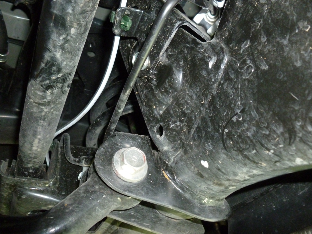
This bracket gave me a lot of grief because a) it didn't line up and b) the bolt provided bottomed out inside on part of the bracket. I had to use a shorter bolt that I had lying around. I also used Toyota bolts I had around instead of the supplied bolts because they have a bit of a tapered lead in that make misalignment much more prone to engagement without cross threading.
skid18a.JPG

skid18b.JPG


Tip:
Relocation of the brake line bracket and extra wire wrap to protect from chafing. Don't let the brake line get too close to the sharp edges of the bracket on the right.
skid19a.JPG

skid19b.JPG

Do the same for the other side as well.
skid22a.JPG


Observation:
The brace for the front of the skid doesn't even come close to sitting flush or even at the same angle. I just tightened it until it felt right.
skid20.JPG


All installed:
skid22b.JPG


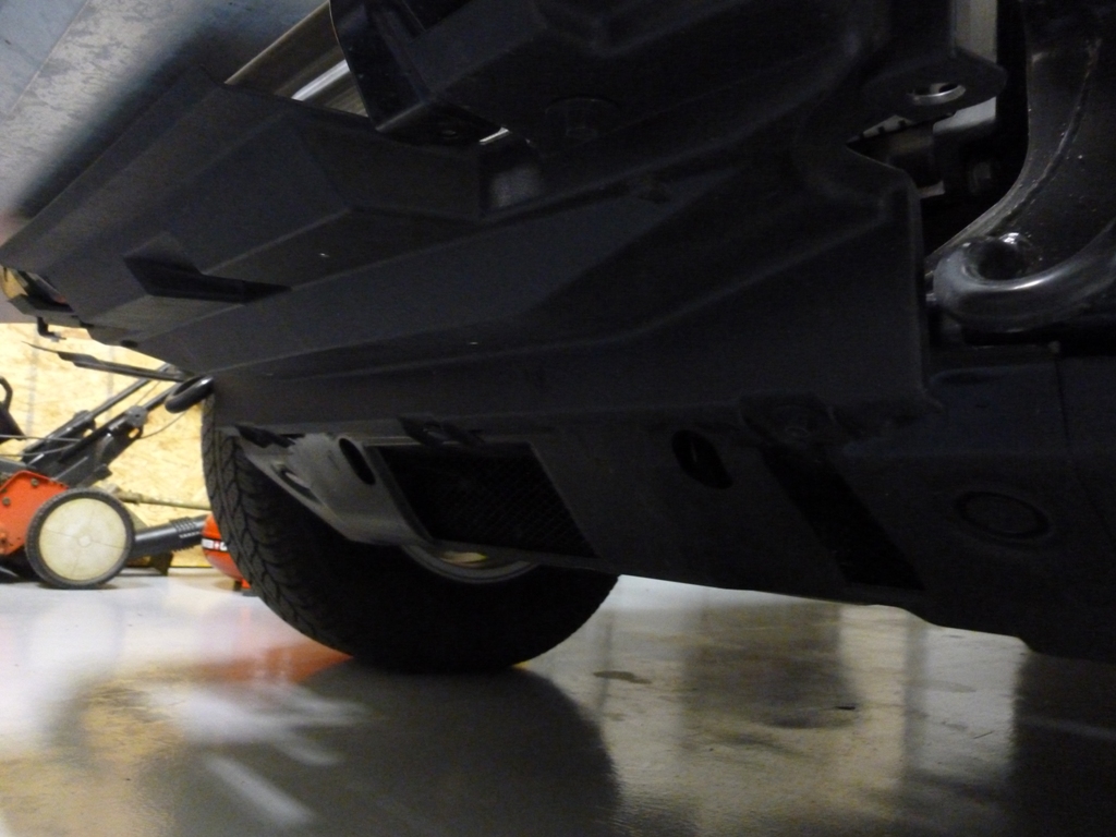
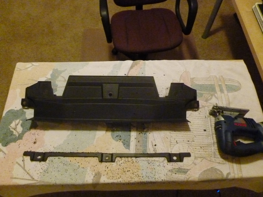
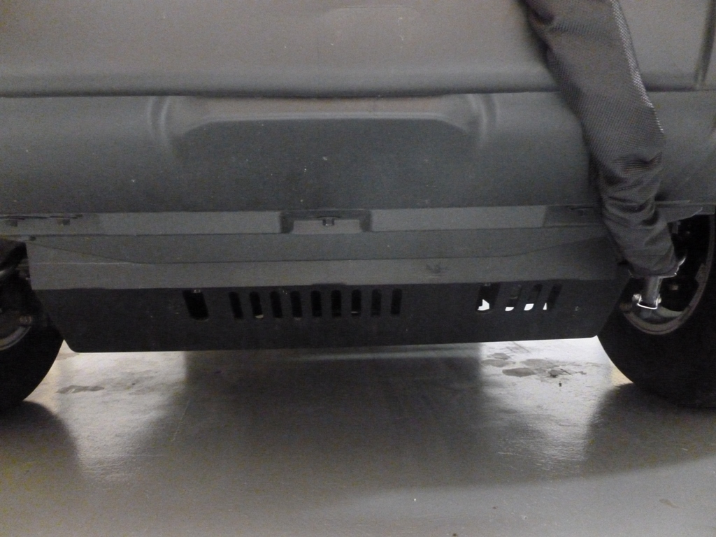
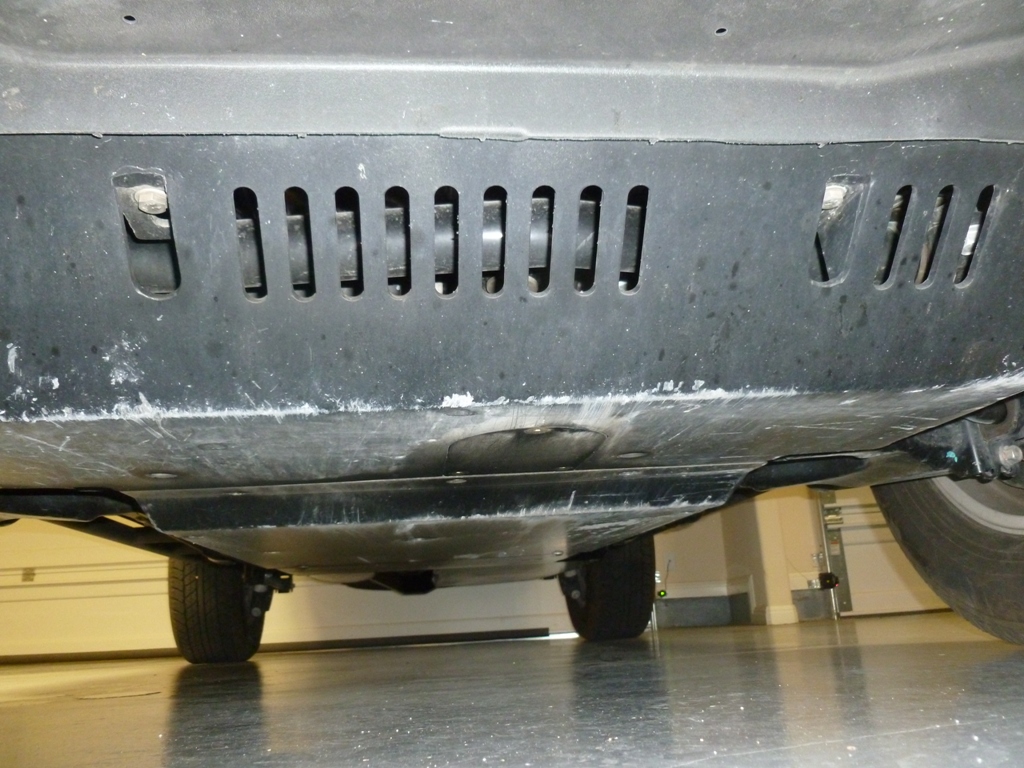
Many winch bumpers come with or offer a metal filler panel that extends from the bumper to the first skid plate. Since I am using the stock bumper, I couldn't find an off the shelf panel so I decided to trim the plastic piece. I don't think it looks all that bad even up close but without it, there is a giant gaping hole and I imagine the radiator is a bit less effective.

Before:
skid05.JPG

Trimming:
skid06.JPG

After:
skid07.JPG


After my first run at Hidden Falls Adventure Park, I'm glad I installed the skids first!
skid23.JPG
 
ARB CKMA12 Compressor + Custom Bracket Install

Parts:
ARB CKMA12 Compressor 9 lbs
Custom Mounting Plate
Hardware: qty:4 M6 x 12mm Flathead Socket head Stainless, qty:4 M6 Washer from ARB kit, qty:4 M6 nylon insert locknut, qty:1 M4 x 6mm Panhead stainless, qty:1 M4 flat washer stainless, qty:2 M8 bolts to mount to the body
ARB Tire Inflation Kit

Reason for Install:
Airing down has considerable benefits on almost all off road surfaces. Airing back up to regular pressures, however, is critical for safe driving at highway speeds. My requirements for a compressor were as follows:
-Air up 4 tires up to 35" within a single duty cycle
-All parts (compressor, tank, regulator, fittings, etc.) must fit in a sensible location

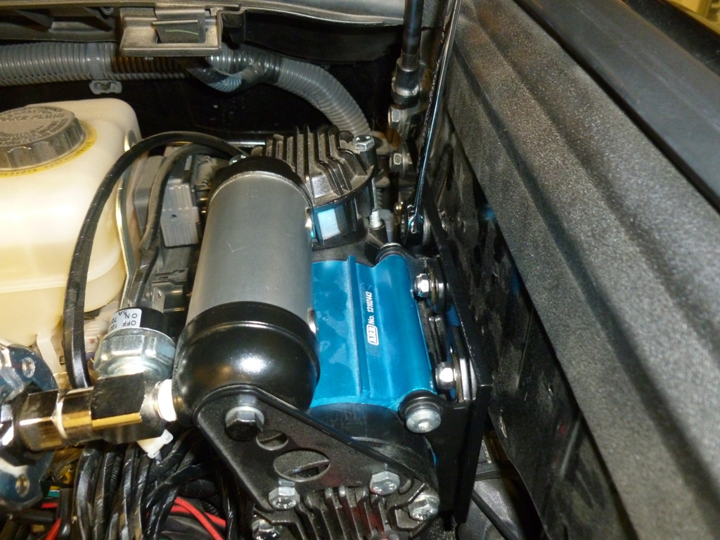
I spent way too much time researching compressors from possibly all available brands. There are awesome compressors out there like the ExtremeAir 007-000 which has a continuous duty cycle. I thought it would be good to mount it in between the passenger side frame rail and slider but a) it is just too large to fit in that location and b) it isn't fully submersible just in case I ford some water. That one also needs to add a tank, regulator, pressure switch, etc. which was just too much effort for something that would likely not fit anywhere I liked without major modifications to the 4Runner. In fact, I couldn't find a reasonably priced yet submersible compressor so my mounting options were somewhere in the cabin or under the hood. Engine heat soak will shorten the duty cycle of most compressors mounted under the hood. However, mounting in the cabin can get pretty annoying. I settled on the CKMA12 because it is a very compact package that contains a 50% duty cycle motor, a reservoir, regulator, pressure switch, wiring harness, and the ability to add on air locker solenoids (if I ever want to put on a front diff locker). After receiving the compressor, taking it apart, inspecting the build quality and design, I've become an ARB fanboy. It takes a lot to impress me when it comes to mechanical design of consumer products as well as documentation and user manuals, but this appears to be a very high quality product. So far I haven't heard of any major negative experiences with this compressor. The compactness of the CKMA12 affords installation near the master cylinder and fuse box so I chose that location for a few reasons:
-It doesn't get direct heat from the headers
-It is easy to access, clean, replace filter, inspect for leaks, etc.
-I plan to put a 2nd battery behind the wheel well arch on the passenger side since I have a smog pump (2013+)
-Making a mounting bracket was pretty easy and cheap
The only thing I don't really like about this bracket design is that it is a cantilever beam and is subject to vibration modes. Given that the compressor vibrates itself like crazy and is mounted on vibration damping legs, I've convinced myself it will be ok. In practice, the .250" plate is more rigid than the body to which it is mounted.
I haven't noticed any EMF effects on neighboring circuitry from the motor so far therefore I think the location is decent.

Now for the custom bracket.

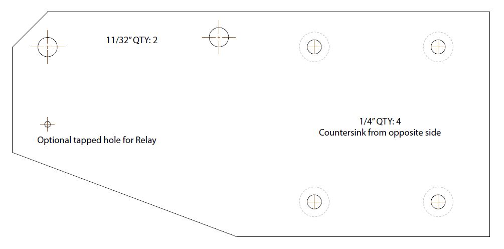
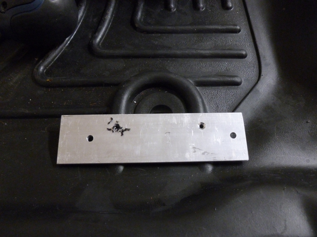
I made this out of some scrap .250" aluminum 6061-T6 I had laying around. If you want to make your own, pick up a plate from ebay or wherever for less than $15. The maximum dimensions are 0.25" X 4.0" X 8.5" and here is a link to a pdf file that you can print out as a template; just make sure it prints to scale!
Mounting Bracket Template
compressor_mounting_bracket.jpg


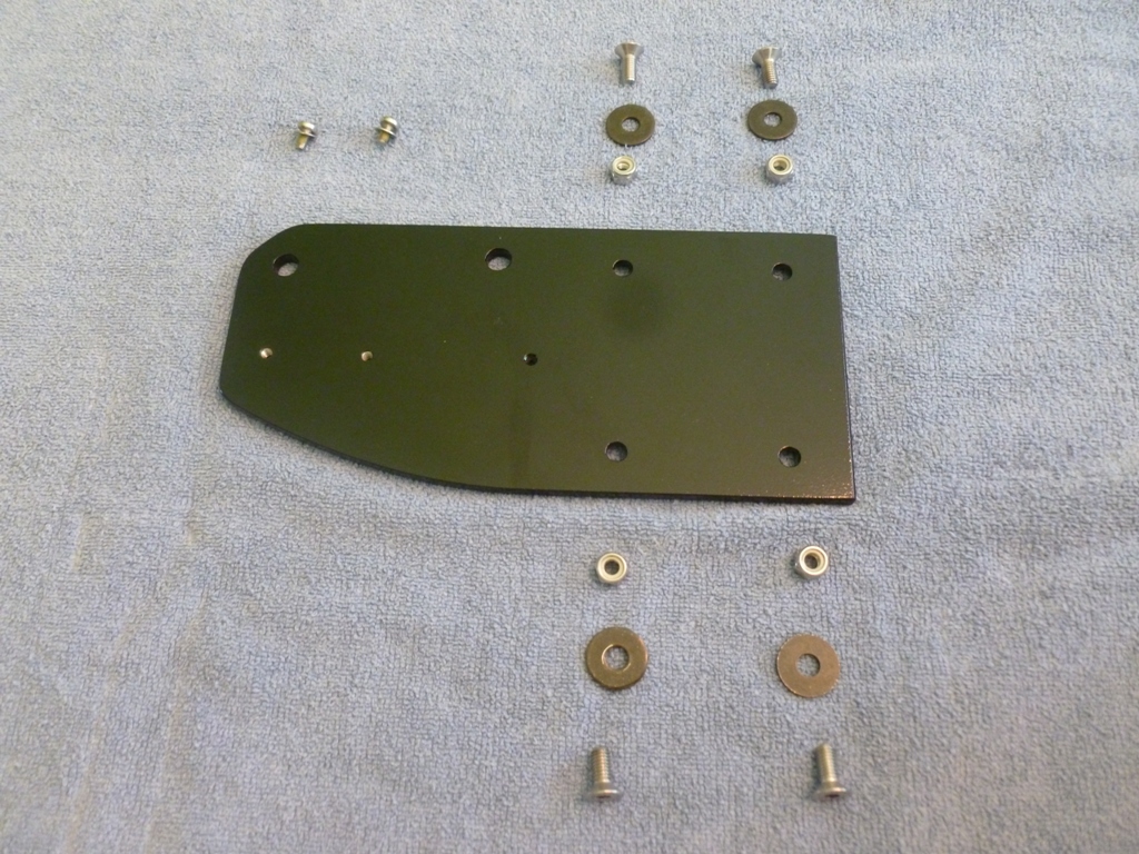
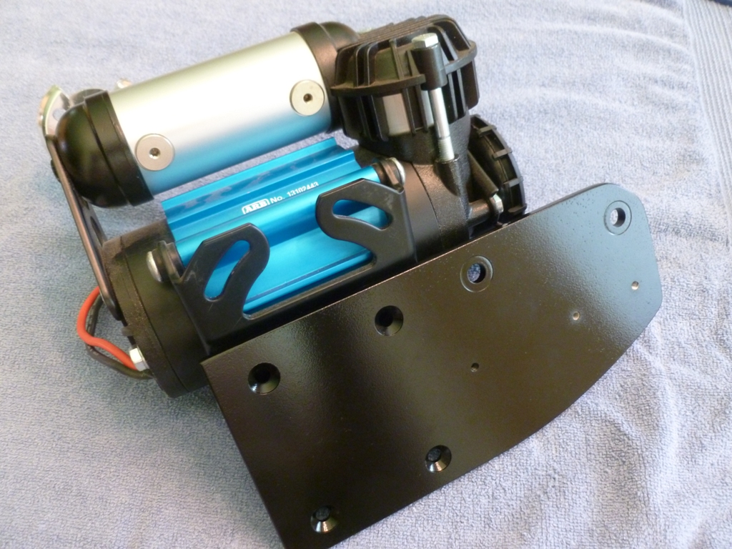
For the install, here is the bracket and the hardware. I ended up only using one of the threaded holes for mounting the relay since the other one was covered up too much by the compressor.
comp01.JPG


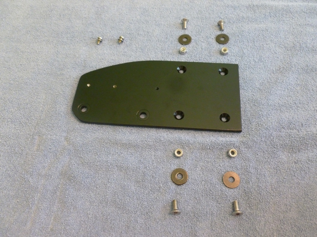
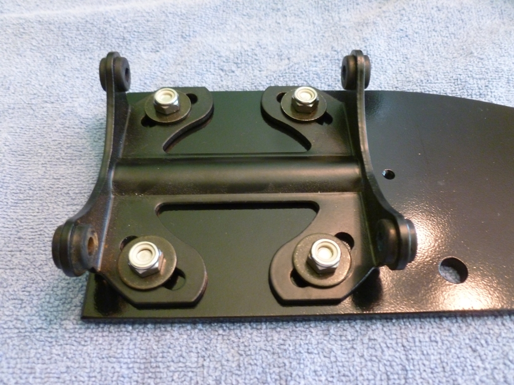
Here is the back side showing the countersink holes and the (optional) slight 0.010"x0.625" counterbores on the holes that mount to the body. The weld nuts have little raised protrusions that dig in to the aluminum when tightened. I chose to give them a little relief but you don't have to. For the countersinks, I am using metric flatheads so I used a 90° sink. You could also use 1/4-20 screws with an 82° sink if you want.
comp02.JPG


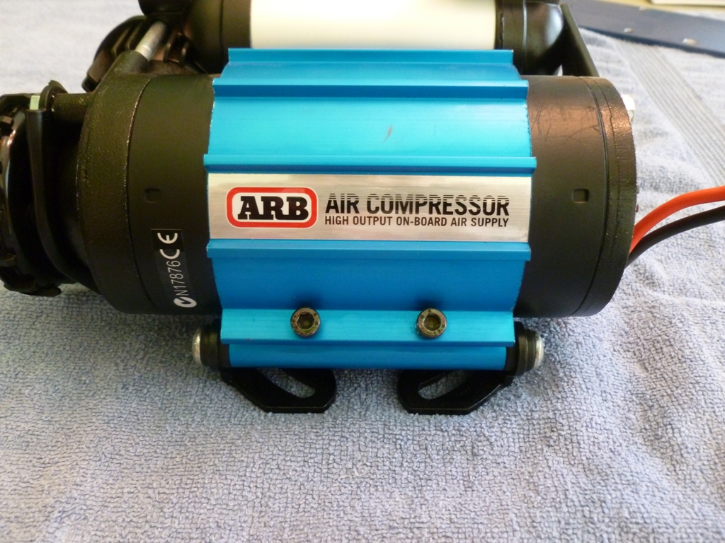
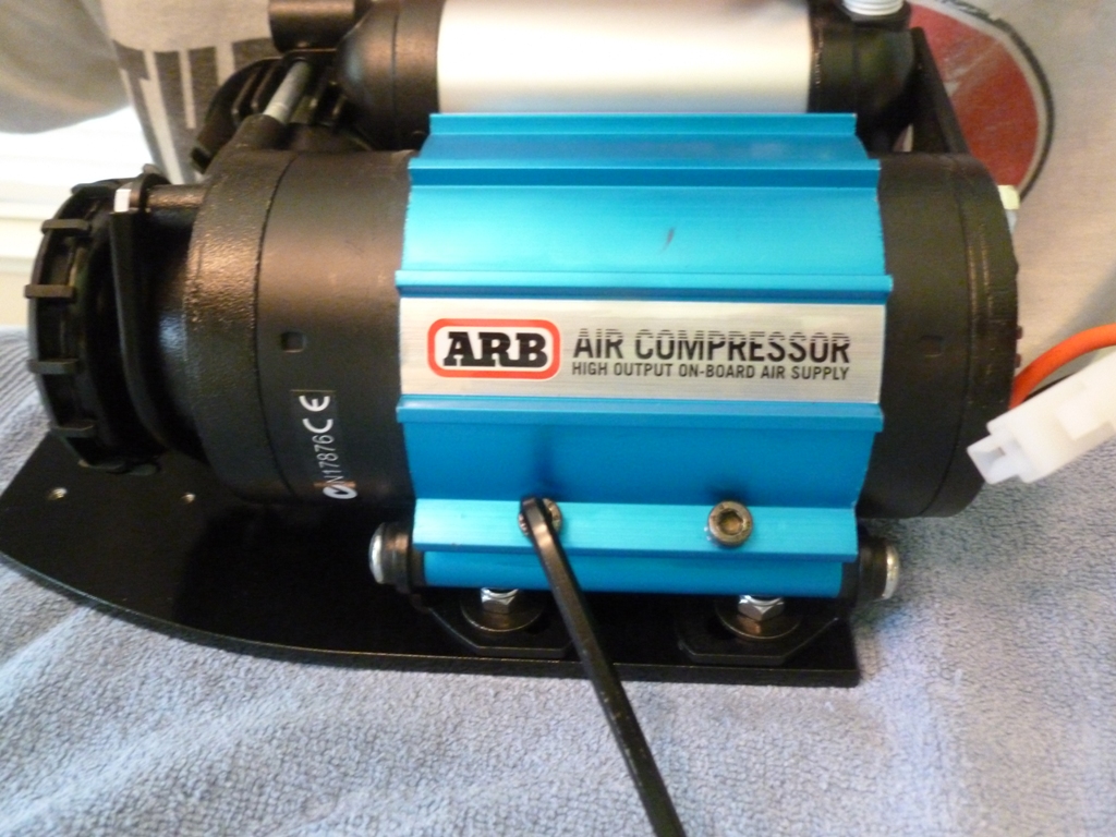
There is quite a bit of rearrangement of the compressor parts to get it into the right orientation. The main thing is to reverse the blue heat sink mount. Start by loosening these black socket head cap screws to be able to loosen the blue heat sink mount.
comp04.JPG


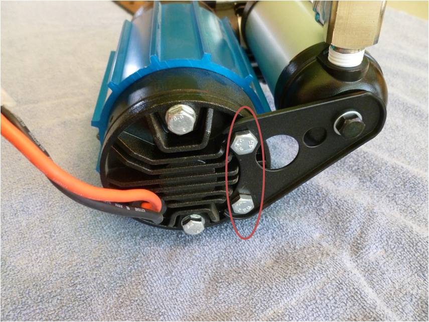
Then undo the two bolts shown here, rotate the black reservoir bracket out of the way, slide off the blue heat sink mount, reverse it, slide it back on, install bolts.
comp03.jpg


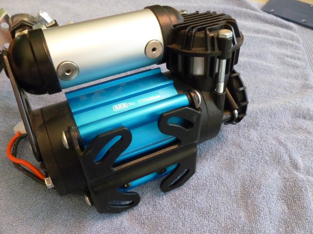
It should look approximately like this:
comp06.JPG


Then take the black base bracket off by removing the four shoulder screws that screw into the blue mount.
comp05.JPG

comp07.JPG


Attach the ARB base bracket to the aluminum mounting bracket using your hardware.
comp08.JPG


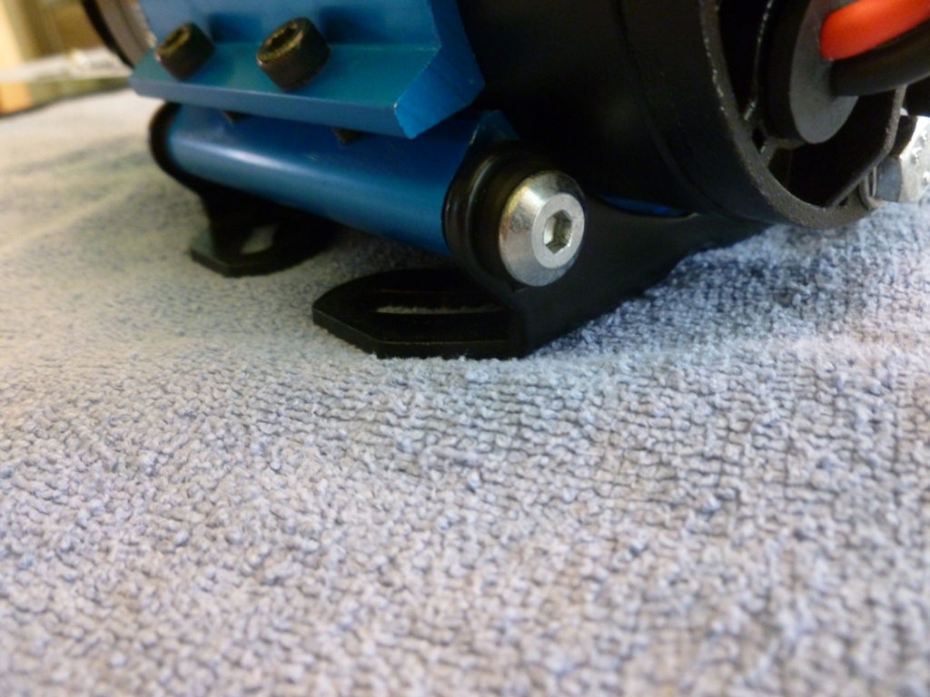
Re-attach the black base bracket to the blue heat sink mount using the four shoulder screws. Re-tighten the blue heat sink mount once you're happy with the position it will take in the engine bay. Note that the custom bracket does not sit perpendicularly to the ground.
comp09.JPG


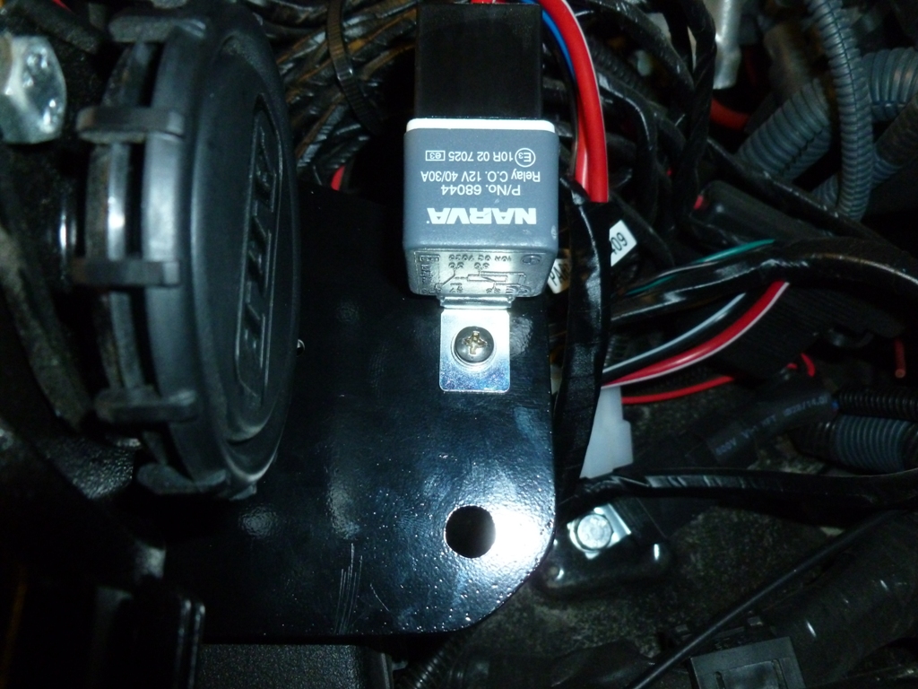
Before you actually install the bracket to the body, mount your relay.
comp10.JPG


Now thread your M8 bolts in and tighten with a box end wrench.
comp11.JPG


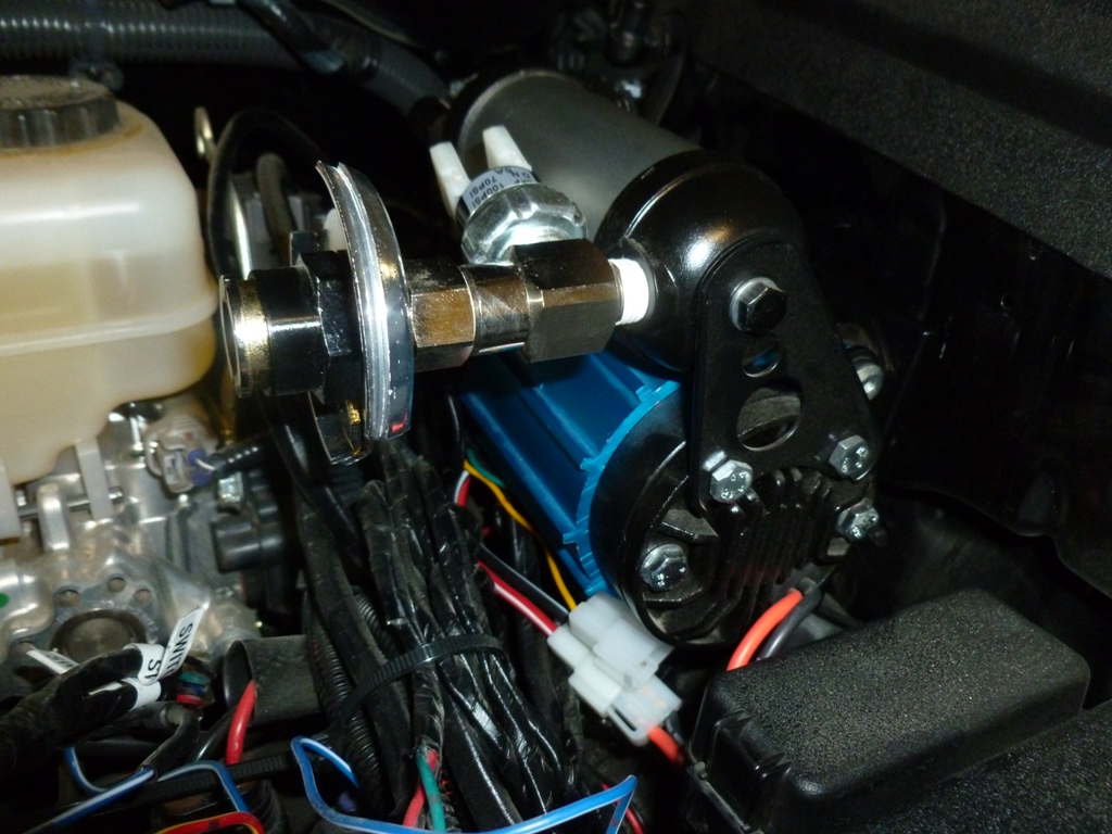
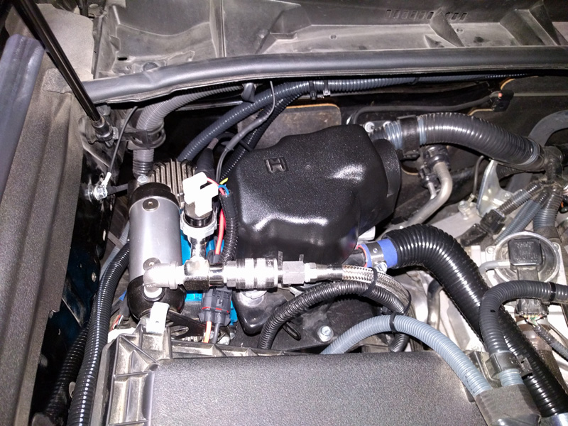
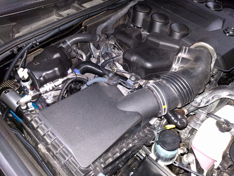
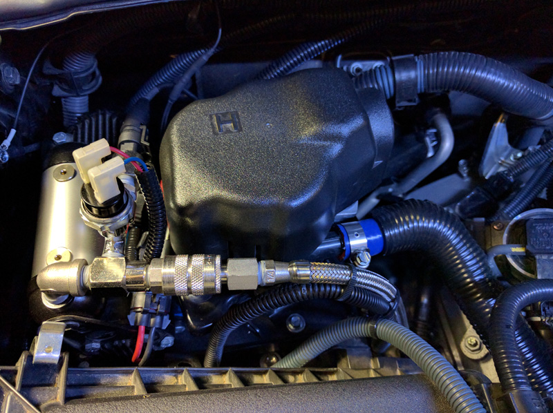
As you can see, I positioned the air chuck from the ARB inflation accessory kit to point parallel to the ground. I did this because it saves me from having to mount the compressor lower and also should minimize the amount of debris that falls into the chuck opening. Almost all ARB installation pictures show it pointing straight up but in my area of work, you never want an exposed connection pointing up.
comp12.JPG


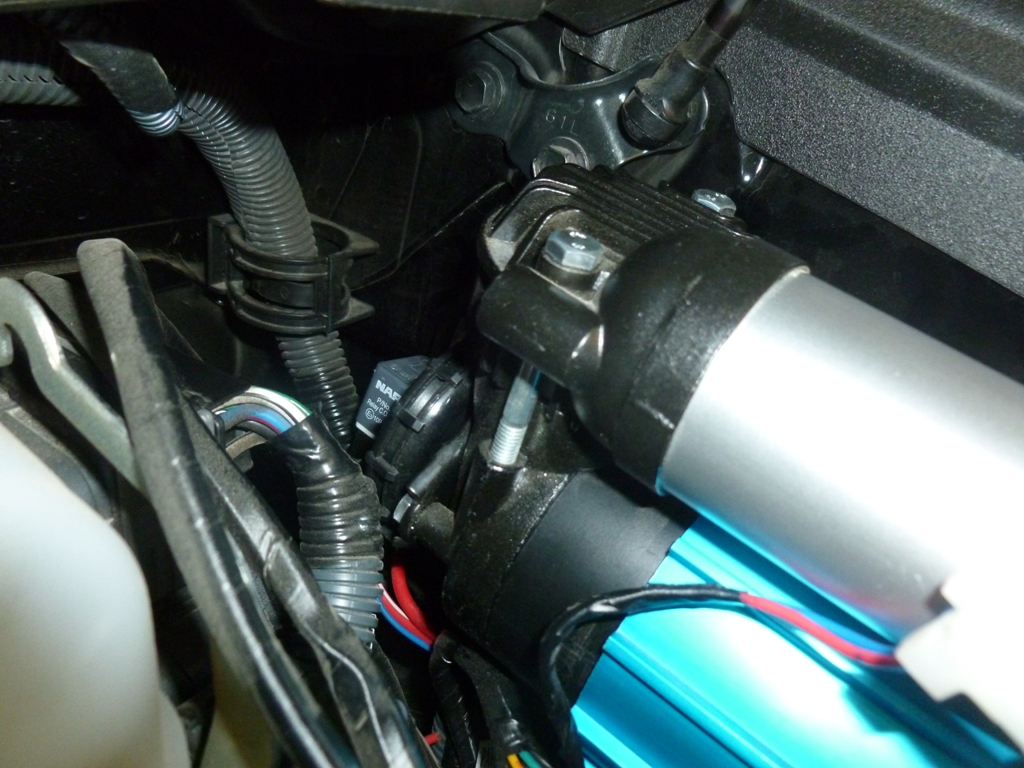
One more picture showing the filter and the relay out of harm's way.
comp13.JPG


If you plan to install the locker solenoids, you may want to consider how they will be oriented and rotate the reservoir appropriately. There may not be enough room to go straight up without hitting the hood. You could rotate the pressure switch to the other side, or face the solenoids toward the body and the connections facing up or down. Hopefully you get the idea and can figure something out.

I hope this write up helps someone.

 
Are you taking any apprenticeship applications?

Your craftsmanship is amazing.

Thanks for sharing!

Haha, there are builds on this forum way nicer than what I'm doing but thanks.

Love the attention to detail. Nice work and thanks for sharing...I learned a lot!
Thanks, I like what you've done with your 2014!

Hopefully the writeups and pictures are helpful to others considering similar mods.
 
Driver Accessible Fire Extinguisher Mount

Parts:
Kidde Aluminum Automotive Fire Extinguisher 2.6 lbs
Custom Mounting Plate: Aluminum stock from Home Depot, .125" x 1.5" x 5.5"
Hardware: qty:2 6-32 Flathead screws, washers, and nuts, qty:2 4-40 Flathead screws, washers, and nuts

Reason for Install:
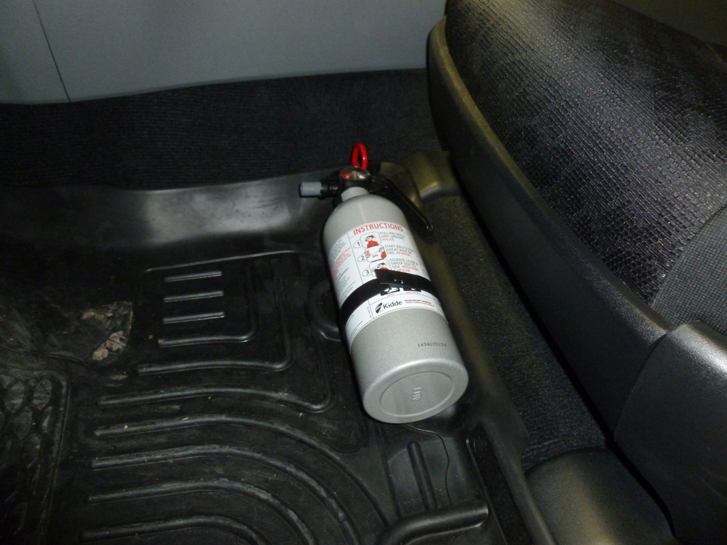
Having a fire extinguisher within arm's reach seems like a no brainer for emergency situations especially if involved in a collision. This location is very accessible from the driver's position where I'll most likely be if I need it yet it doesn't get in the way of my feet or the travel of the seat.

Caution: I think this particular extinguisher is rated up to 120° F. If parking in a hot desert, it may be a good idea to cover it with a towel or something to shield it from direct sunlight and reduce the mess if it leaks.

The mounting plate is pretty simple and just provides a solid backing for the plastic fire extinguisher mount. I suggest getting everything lined up exactly how you want it and then marking your holes accordingly.
fe01.JPG


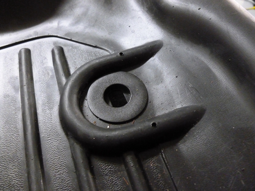
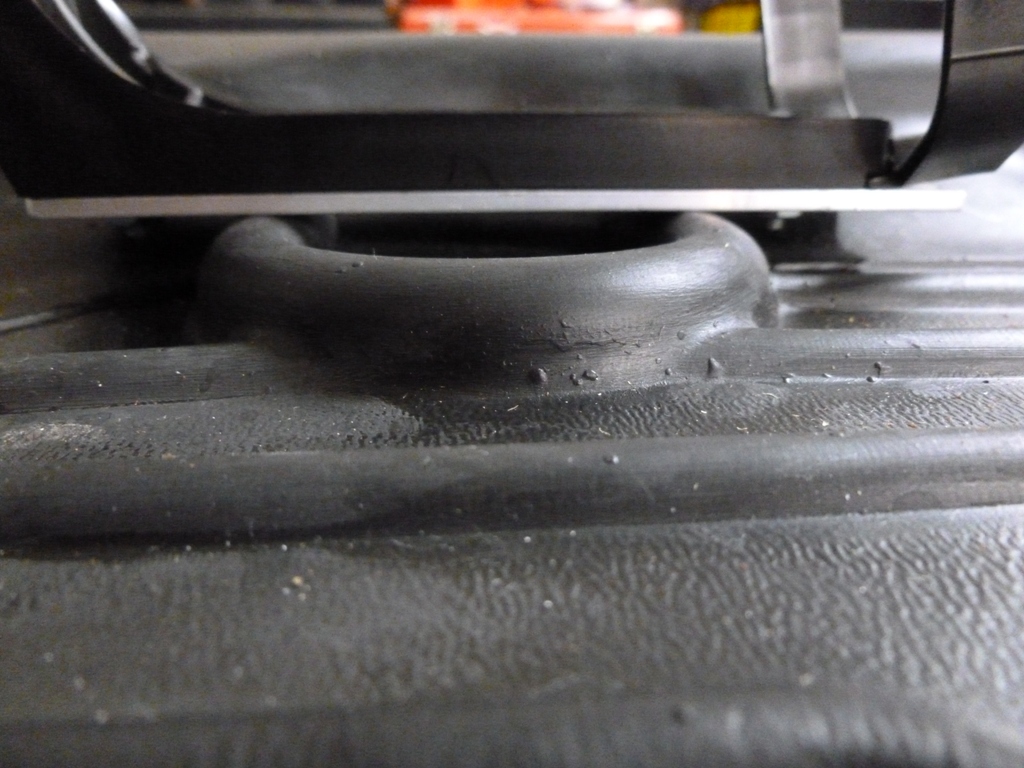
Here are the holes drilled into the Husky Liner. I used 4-40 which is small enough to fit on the underside of the molded channel.
fe02.JPG

fe03.JPG


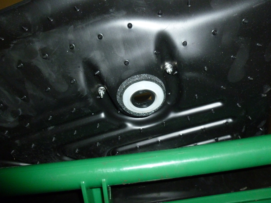
This picture shows the stackup looking toward the rear of the car. I used 6-32 (I think) screws to attach the black mount to the aluminum plate.
fe04.JPG


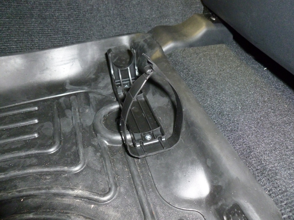
The mount and plate installed.
fe05.JPG


The final product.
fe06.JPG
 
Have you been able to use your ARB compressor much, and if so how do you like it? I'm debating between the CKMA12 vs the CKMTA12, and while I don't plan on running air tools I'm not known for much patience either, so curious to know people's experiences with the CKMA12, how long it takes to air up 33" tires, etc.
 
Parts:
ARB CKMA12 Compressor 9 lbs
Custom Mounting Plate
Hardware: qty:4 M6 x 12mm Flathead Socket head Stainless, qty:4 M6 Washer from ARB kit, qty:4 M6 nylon insert locknut, qty:1 M4 x 6mm Panhead stainless, qty:1 M4 flat washer stainless, qty:2 M8 bolts to mount to the body
ARB Tire Inflation Kit

Reason for Install:
Airing down has considerable benefits on almost all off road surfaces. Airing back up to regular pressures, however, is critical for safe driving at highway speeds. My requirements for a compressor were as follows:
-Air up 4 tires up to 35" within a single duty cycle
-All parts (compressor, tank, regulator, fittings, etc.) must fit in a sensible location

I spent way too much time researching compressors from possibly all available brands. There are awesome compressors out there like the ExtremeAir 007-000 which has a continuous duty cycle. I thought it would be good to mount it in between the passenger side frame rail and slider but a) it is just too large to fit in that location and b) it isn't fully submersible just in case I ford some water. That one also needs to add a tank, regulator, pressure switch, etc. which was just too much effort for something that would likely not fit anywhere I liked without major modifications to the 4Runner. In fact, I couldn't find a reasonably priced yet submersible compressor so my mounting options were somewhere in the cabin or under the hood. Engine heat soak will shorten the duty cycle of most compressors mounted under the hood. However, mounting in the cabin can get pretty annoying. I settled on the CKMA12 because it is a very compact package that contains a 50% duty cycle motor, a reservoir, regulator, pressure switch, wiring harness, and the ability to add on air locker solenoids (if I ever want to put on a front diff locker). After receiving the compressor, taking it apart, inspecting the build quality and design, I've become an ARB fanboy. It takes a lot to impress me when it comes to mechanical design of consumer products as well as documentation and user manuals, but this appears to be a very high quality product. So far I haven't heard of any major negative experiences with this compressor. The compactness of the CKMA12 affords installation near the master cylinder and fuse box so I chose that location for a few reasons:
-It doesn't get direct heat from the headers
-It is easy to access, clean, replace filter, inspect for leaks, etc.
-I plan to put a 2nd battery behind the wheel well arch on the passenger side since I have a smog pump (2013+)
-Making a mounting bracket was pretty easy and cheap
The only thing I don't really like about this bracket design is that it is a cantilever beam and is subject to vibration modes. Given that the compressor vibrates itself like crazy and is mounted on vibration damping legs, I've convinced myself it will be ok. In practice, the .250" plate is more rigid than the body to which it is mounted.
I haven't noticed any EMF effects on neighboring circuitry from the motor so far therefore I think the location is decent.

Now for the custom bracket.

I made this out of some scrap .250" aluminum 6061-T6 I had laying around. If you want to make your own, pick up a plate from ebay or wherever for less than $15. The maximum dimensions are 0.25" X 4.0" X 8.5" and here is a link to a pdf file that you can print out as a template; just make sure it prints to scale!
Mounting Bracket Template
compressor_mounting_bracket.jpg


For the install, here is the bracket and the hardware. I ended up only using one of the threaded holes for mounting the relay since the other one was covered up too much by the compressor.
comp01.JPG


Here is the back side showing the countersink holes and the (optional) slight 0.010"x0.625" counterbores on the holes that mount to the body. The weld nuts have little raised protrusions that dig in to the aluminum when tightened. I chose to give them a little relief but you don't have to. For the countersinks, I am using metric flatheads so I used a 90° sink. You could also use 1/4-20 screws with an 82° sink if you want.
comp02.JPG


There is quite a bit of rearrangement of the compressor parts to get it into the right orientation. The main thing is to reverse the blue heat sink mount. Start by loosening these black socket head cap screws to be able to loosen the blue heat sink mount.
comp04.JPG


Then undo the two bolts shown here, rotate the black reservoir bracket out of the way, slide off the blue heat sink mount, reverse it, slide it back on, install bolts.
comp03.jpg


It should look approximately like this:
comp06.JPG


Then take the black base bracket off by removing the four shoulder screws that screw into the blue mount.
comp05.JPG

comp07.JPG


Attach the ARB base bracket to the aluminum mounting bracket using your hardware.
comp08.JPG


Re-attach the black base bracket to the blue heat sink mount using the four shoulder screws. Re-tighten the blue heat sink mount once you're happy with the position it will take in the engine bay. Note that the custom bracket does not sit perpendicularly to the ground.
comp09.JPG


Before you actually install the bracket to the body, mount your relay.
comp10.JPG


Now thread your M8 bolts in and tighten with a box end wrench.
comp11.JPG


As you can see, I positioned the air chuck from the ARB inflation accessory kit to point parallel to the ground. I did this because it saves me from having to mount the compressor lower and also should minimize the amount of debris that falls into the chuck opening. Almost all ARB installation pictures show it pointing straight up but in my area of work, you never want an exposed connection pointing up.
comp12.JPG


One more picture showing the filter and the relay out of harm's way.
comp13.JPG


If you plan to install the locker solenoids, you may want to consider how they will be oriented and rotate the reservoir appropriately. There may not be enough room to go straight up without hitting the hood. You could rotate the pressure switch to the other side, or face the solenoids toward the body and the connections facing up or down. Hopefully you get the idea and can figure something out.

I hope this write up helps someone.
i may bug you about more information about this plate if i think i am right where its located. is in on the drivers side fender wall somewhat near the fuse box?
 
Have you been able to use your ARB compressor much, and if so how do you like it? I'm debating between the CKMA12 vs the CKMTA12, and while I don't plan on running air tools I'm not known for much patience either, so curious to know people's experiences with the CKMA12, how long it takes to air up 33" tires, etc.

I am very happy with it after several uses including two weeks on Moab and Colorado trails airing up about once a day. It is not fast like a proper 20 gallon tank compressor in your garage but it is not slow like a $30 plug into the cigarette lighter and burn up the motor after a few uses wal-mart special. If your budget and your under hood space allows for the ARB twin, get it and don't look back. But if you have limited space and want a compressor that isn't quite as fast but still stands up to the heat/vibration/dust/etc., the ARB single is a great choice. When selecting a compressor, get one that can air up your tires before reaching the thermal cut (duty cycle). From the research I did before selecting the ARB CKMA12, it had ample ability to air up 33's before cutting out even in a hot ambient (50% duty cycle). On the other hand, the CKMTA12 is 100% duty cycle so you can air up your entire convoy.
 
any new mods?

i just read through your thread and this is freaking awesome! pic heavy but awesome!

also curious as to why you went with budbuilt skids instead of shrockworks. Shrockworks is close and has a little cutout for the oil filter. Shrockworks is steel, your buds are aluminum. was it weight savings?
 
Damn fine build. I always like a good subtle build, kind of a sleeper. I wish I had the patience to be that meticulous with fitment and running, but I am cursed when I see the light at the end of the tunnel to trip and fall face first. That's when it looks like I got into a fight with a honey badger.
 
Diff Breather Manifold

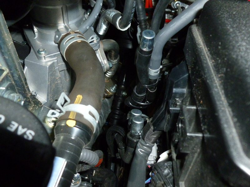
There are several great posts about this mod so I won't get into the details. Basically, several breather ports on the drivetrain use one way valves and some of them live below the water fording line. I agree that it is a good idea to relocate them to a higher spot and use a filter to allow two way flow for pressure equalization when your differentials experience dynamic rapid thermal "differentials" during water crossings.
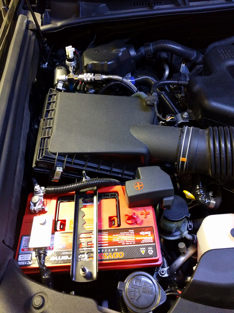
I combined the rear diff and e-lock into a 5/16" fuel/vapor rated hose and routed to the front to join up with the others coming from the rest of the drivetrain.
breathe00.jpg


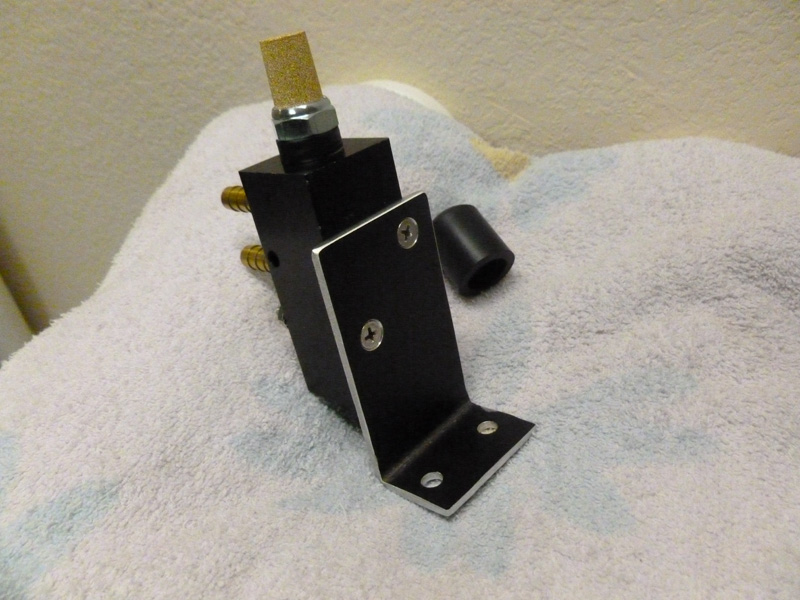
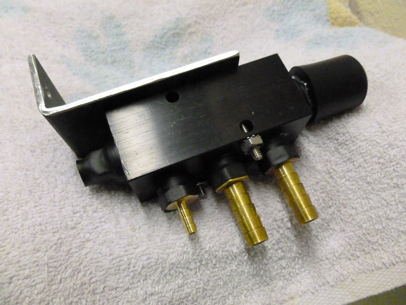
I temporarily used the one way valve shown above until I could complete a manifold. This manifold has a sintered filter at the top with a rubber cap that fits around the hex and still allows air to flow to the filter element while rejecting most spray down when I'm hosing down the engine bay.
breathe01.jpg

breathe02.jpg


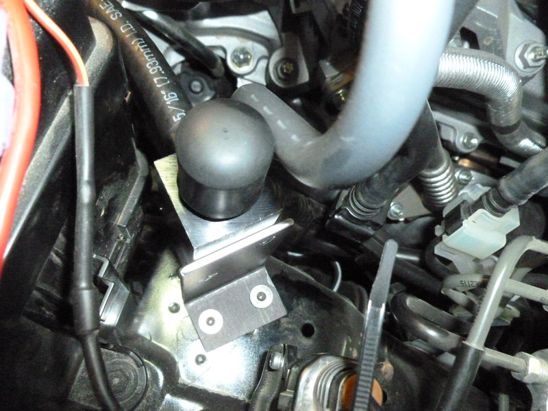
Not my best looking bracket but I was in a hurry and it is mostly hidden from view anyway. Now that the breathers are combined, I can easily extend the height of the filter to another taller location if I decide to get a snorkel and prepare for deeper water fording. For now, it is sitting on the wheel arch.
breathe03.jpg
 
Second Battery, Smog Relocation, Compressor Relocation

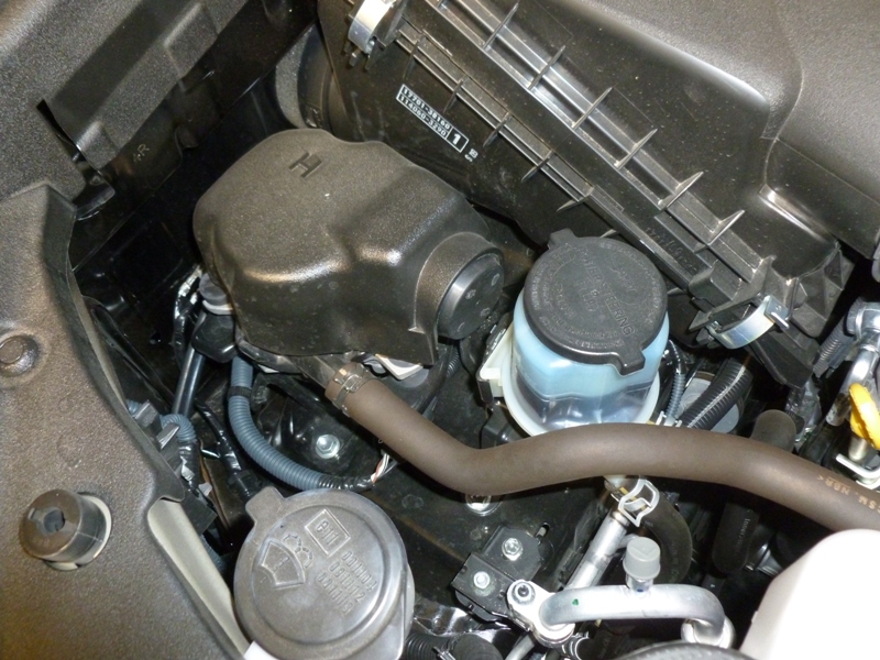
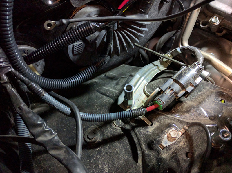
2013+ T4Rs have a smog pump where you would like to logically place the dual battery.
battery01.JPG


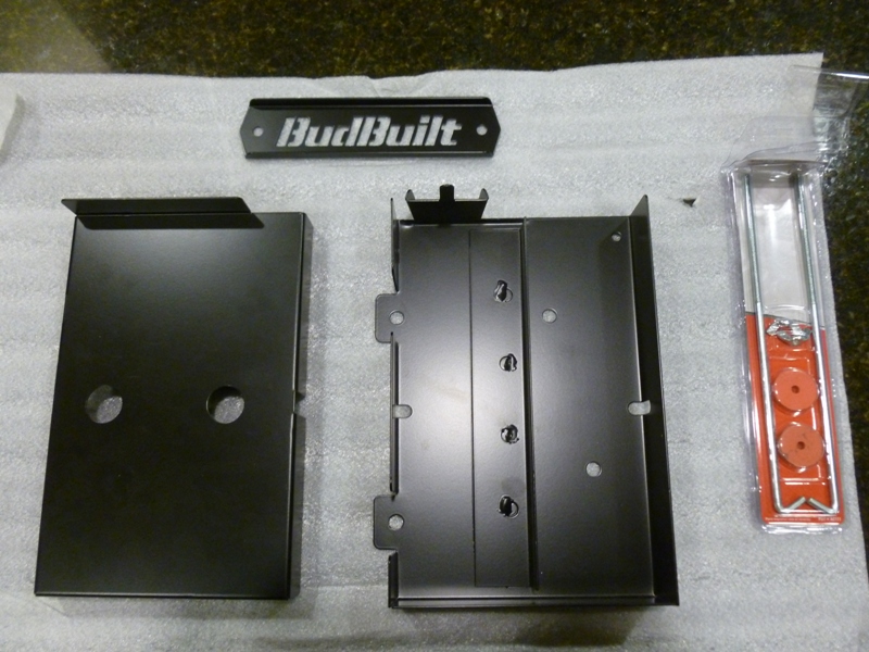
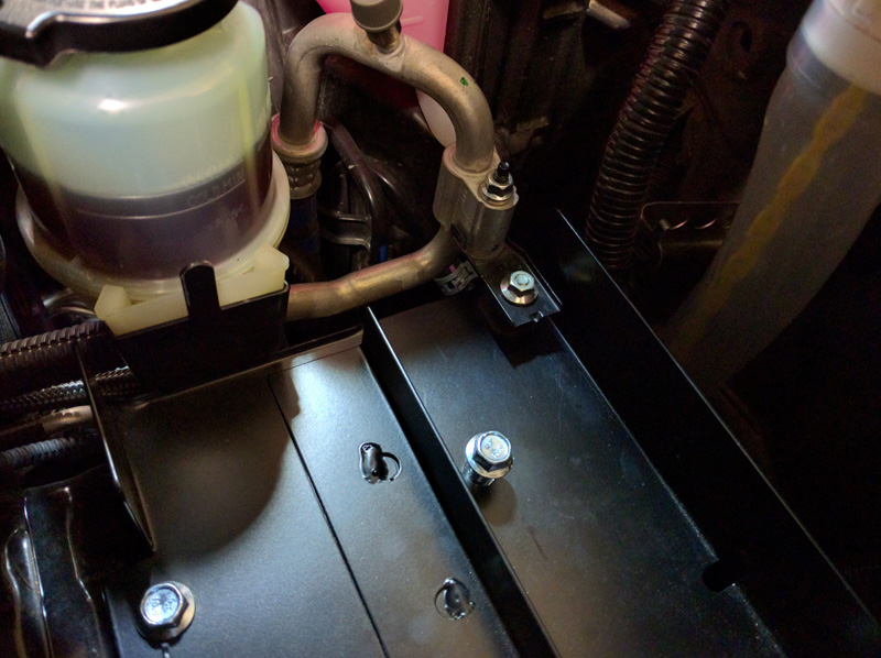
I already had a Bud Built mounting plate/bracket kit but using it would require relocating the smog pump.
battery05.JPG


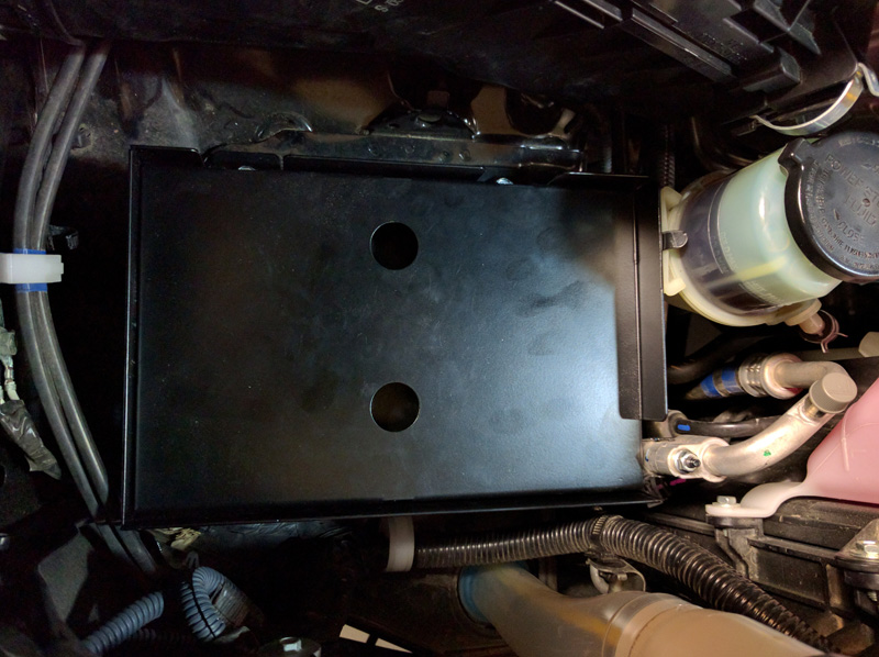
I designed my own battery bracket kit to sit behind the wheel arch:
battery02.JPG


However, after fabbing it up, I thought some more about the amount of spot welds on the body in that area compared to the more beefy ones in front where the smog is (since that area seems to have been designed for a battery). Late in the game, I also realized I could fit the smog pump and the ARB compressor back there on the bracket I already had fabbed. This freed up the better battery bracket location.

Refer to this thread for more info about the BB battery bracket.

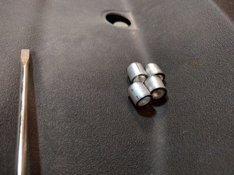
I decided to use some custom 0.5" spacers to get everything to line up just exactly right and optimize the amount of pushing on the AC lines needed with other constraints.
battery10.jpg


Getting the fasteners lined up before torquing.
battery11.jpg


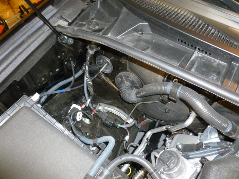
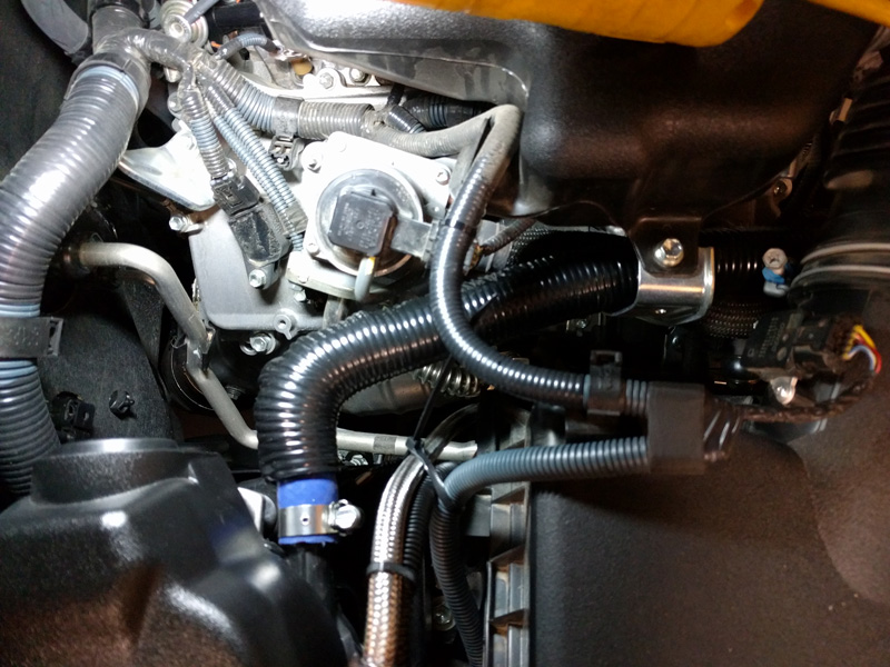
I put some corrugated plastic tube over some of the hoses that now rubbed a little bit with the AC and PS lines.
battery12.jpg


Now ready for the battery.
battery13.jpg


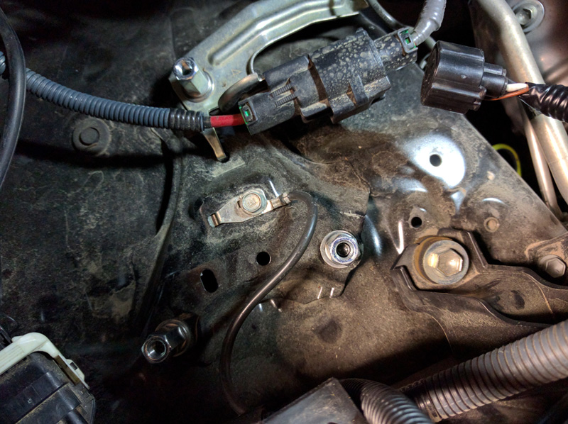
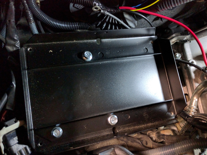
For the smog/compressor bracket, I used some weld studs on the body with coupling nuts.
smog_02b.jpg

smog_03.jpg


My base bracket sits on top using spacers and washers to level out and distribute the force. The bottom bracket has two tack welded braces that were designed to provide rigid support for the battery top plate and are a little over kill for just the smog and compressor.
smog_04.jpg


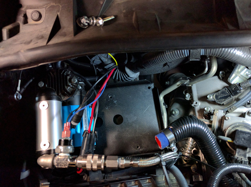
I first mounted the compressor to the top plate, then lowered the top plate onto the bottom plate and completed my connections.
smog_05.jpg


Before installing the smog pump to the top bracket, I had to first undo some electrical tape on the wiring harness and reroute it to behind the wheel arch/air filter. It is long enough. I also had to make a new hose to connect the pump to the hose manifold on the front of the engine. I opted for high temp silicone vacuum rated reinforced vapor hose with stainless clamps and wrapped with high temp nylon corrugated tube then wrapped with high temp electrical tape from 3M. This is because the hose sits above the thermal plume coming from the header heat shield down below.
smog_06.jpg


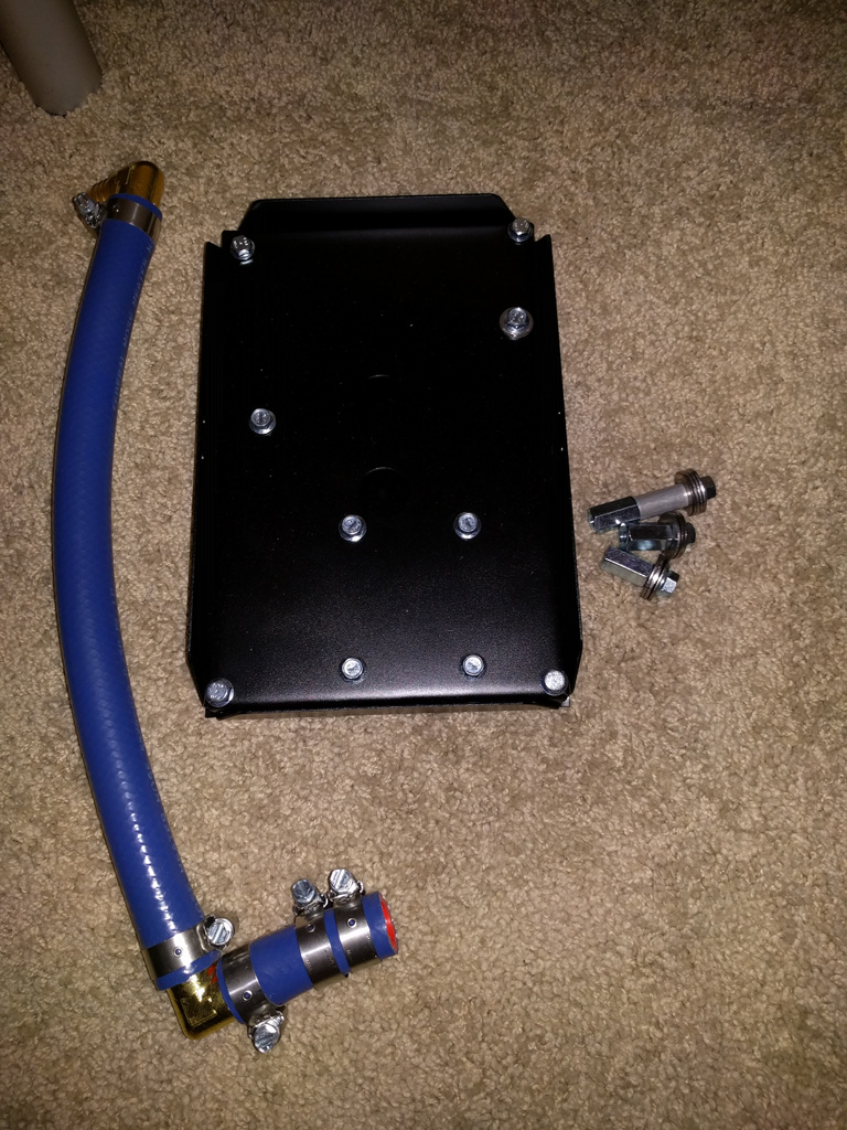
The bracket kit before install looks like this:
smog_kit.jpg


After install:
smog_13.jpg

smog_14.jpg

smog_20.jpg


And finally with the Odyssey PC1500 34M battery installed:
smog_01.jpg
 

Members online

Forum statistics

Threads
278,307
Messages
3,554,055
Members
248,016
Latest member
Advally Service

Trending content

Back
Top