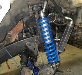
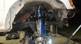
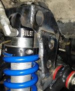
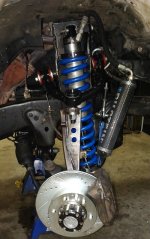
External Resi Coilovers... Not King, Icon, Fox, SAW, or Radflo

can you regain some of your up travel by getting a long travel lower control arm?

I could, but that's not my priority at the moment. I may build a custom LCA setup in the future once I've had more refined CAD experience and more practice welding / working with suspension geometry.
 
Regardless of these being digressive or progressive, are they valved for a 4Runner...?

I'm thinking that's less than likely by the need to "ream" the lower mounting hole and purchase a top plate.

Or will you be re-valving them when you take them apart to replace that hose fitting?

Sure an Icon setup is spendy, but once you buy the reservoir mounts, the top plate, springs and the right hose fitting you're looking at another ~$400 (depending on the prices you're able to find.

Then, for the average user (I don't know if you're doing it yourself or not) you're looking at at least another couple hundred dollars to have these brand new units completely disassembled in order to have the new hose fittings installed, the mis-matched springs installed, and the lower mount "reamed" to fit.

For the average user, that's a good bit of down time, the hassle of finding a shop that will do the work (and do it correctly) and the cost of time and fuel to drop them off and pick them up.

So if you paid $360 (which the average user will not be paying- they're "on sale" for $483.55 each at DSM right now) you're looking at (if you do the work) an extra ~$400 and hours of labor to get something working for your vehicle.

If you don't do the work you're looking at at least an extra $600.

If you buy them at retail you'll be over the cost of an Icon, King, or Fox setup by the time you have them ready to run. In fact, if you ordered through a place like Total Automotive you'd likely be able to purchase an Icon setup with remote reservoirs and the CDC valving.

And they would come assembled, ready to run, to your door.

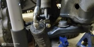
With the parts being accounted for, once I got all the parts I was able to do all of the work myself including pulling them apart and pressurizing! Didn't spend a cent on labor! Worth it in the end!
 
Nearing 1 year UPDATE

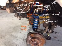
After having driven for quite some time on this setup, many miles logged, a 7,000+ mile trip out to explore Colorado from Georgia and back, 1,300+/- offroad miles, and countless trips to the Chattahoochee National Forest of North Georgia here in my backyard I have decided to continue forward with this front setup. Initially I thought about a long travel setup and I will eventually get there, but with the 4wd conversion being done this winter, I also wanted to re-gain the bump-travel I lost when adding these longer CO's . I will only be raising the effective upper eyelet height, BUT I will go just a bit further than factory to maximize my bump-travel.
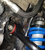
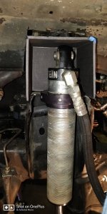
How: I would like to either plate the coil bucket and modify it to create clearance for the 2.5" body to sit 'inside' of the coil bucket and using a double shear eyelet mount, hopefully raise the shock body to where I have maximum bump travel.This triangulated top mount will definitely be strong enough to withstand the forces applied to it (more so than the factory bucket)
sl3_LI.jpg

I will be able to use the modified upper mount and at the same time use the Factory LCA geometry to keep the same wheel track width. I hate the idea of 7" wider overall with LT and I have had the urge to build something that is a true Mid-travel design using the Uniball UCA's that we all know and love and without the $$$$ that Long Travel wants from us. I have 8" of shock stroke available to me so, I intend to use most, if not, all of it!

Stay Tuned!
 

Attachments

  • sl3_LI.jpg
    sl3_LI.jpg
    57.4 KB · Views: 1,178
Update a few years on...

It's been nearly 4 years

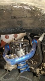
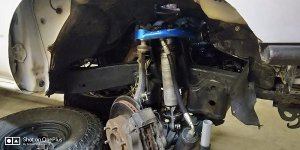
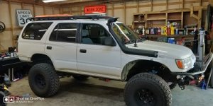
I installed these coilovers on a 2wd vehicle and I ultimately went through and painstakingly thought through how I would go about designing this mount to get all of the travel back out of the factory suspension.

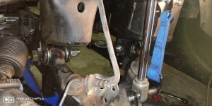
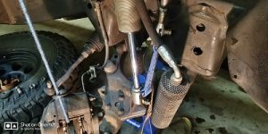
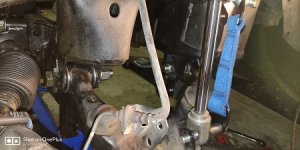
Problem: I lost a few inches of up-travel due to stuffing an 8" travel coilover in the factory location.

Solution: Design a new mount to go in the place of the existing tower to get that travel back.

How:Prayers and CAD.

Commitment:
 

Attachments

  • problem1.jpg
    problem1.jpg
    77.5 KB · Views: 212
Photo dump

Problem and starting to get to the solution

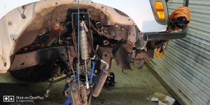
Chop, chop, chop
 

Attachments

  • problem2.jpg
    problem2.jpg
    59.5 KB · Views: 201
  • chop1.jpg
    chop1.jpg
    39.3 KB · Views: 202
  • IMG_20200526_232131.jpg
    IMG_20200526_232131.jpg
    53.1 KB · Views: 230
  • IMG_20200526_224816.jpg
    IMG_20200526_224816.jpg
    56.2 KB · Views: 201
  • 23559-fcaa9a81e43ae400989707ad392f578d.jpg
    23559-fcaa9a81e43ae400989707ad392f578d.jpg
    30.7 KB · Views: 205
Fitting and measuring

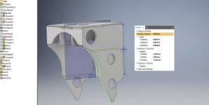
All of the work for figuring out the material thickness, width/length/etc. of the tower will be done in CAD, but I was getting the clearance for the coilover done with grid board.
 

Attachments

  • fit1.jpg
    fit1.jpg
    43 KB · Views: 208
  • fit2.jpg
    fit2.jpg
    50.2 KB · Views: 198
  • fit3.jpg
    fit3.jpg
    48 KB · Views: 208
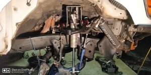
4Runner May Update

Here's a photo for reference after I had chopped the fenders and attempted to fit the 35's without tubbing.... Laughing at that now!
 

Attachments

  • 4R may update.jpg
    4R may update.jpg
    41.4 KB · Views: 196
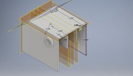
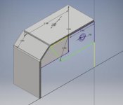
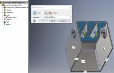
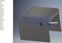
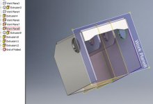
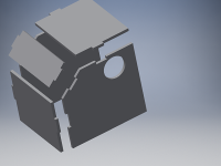
Here's some fun on the computer

This is sort of the progression after doing the finite element analysis for the mount. I sort of know what I'm doing, but I'm only just scratching the surface.
 

Attachments

  • Tower 2.jpg
    Tower 2.jpg
    16.2 KB · Views: 198
  • Tower 6.jpg
    Tower 6.jpg
    10.7 KB · Views: 198
  • FEA 2.jpg
    FEA 2.jpg
    23 KB · Views: 188
  • Tower V2.8.jpg
    Tower V2.8.jpg
    15.5 KB · Views: 189
  • Coilover Tower Final.jpg
    Coilover Tower Final.jpg
    17.8 KB · Views: 196
  • View2.png
    View2.png
    106.3 KB · Views: 200
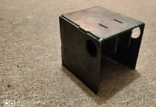
Update: CNC done on the prototype and some refinement

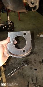
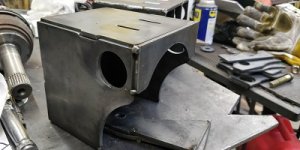
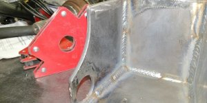
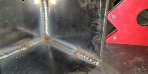
Got the CNC to cut the parts out, tacked together, and fitted to check the dimensions. This is a very crude version and you can see that I took lots of material away afterwards and added some cleaner lines.
 

Attachments

  • IMG_20200526_215127.jpg
    IMG_20200526_215127.jpg
    37.1 KB · Views: 199
  • IMG_20200526_224816.jpg
    IMG_20200526_224816.jpg
    56.2 KB · Views: 200
  • IMG_20200526_232131.jpg
    IMG_20200526_232131.jpg
    53.1 KB · Views: 186
  • dimensions.jpg
    dimensions.jpg
    16.7 KB · Views: 195
Update: New parts cut

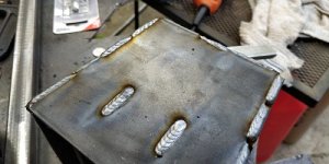
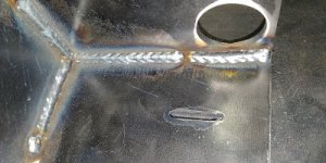
Got the final part cut out, and tacked. I couldn't wait any longer so, I just got after it and started burning.
 

Attachments

  • IMG_20200529_192824.jpg
    IMG_20200529_192824.jpg
    40.3 KB · Views: 188
  • IMG_20200530_003007.jpg
    IMG_20200530_003007.jpg
    43.1 KB · Views: 184
  • IMG_20200531_220341.jpg
    IMG_20200531_220341.jpg
    41.2 KB · Views: 196
  • IMG_20200715_214516.jpg
    IMG_20200715_214516.jpg
    40.9 KB · Views: 186
  • IMG_20200715_214610.jpg
    IMG_20200715_214610.jpg
    46.8 KB · Views: 190
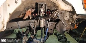
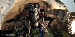
Putting it back together

Re-assembly time with all the new shiny parts
 

Attachments

  • IMG_20200716_235952.jpg
    IMG_20200716_235952.jpg
    82.9 KB · Views: 192
  • IMG_20200717_214943.jpg
    IMG_20200717_214943.jpg
    42.4 KB · Views: 203
  • IMG_20200717_235459.jpg
    IMG_20200717_235459.jpg
    51.6 KB · Views: 197
  • IMG_20200717_235508.jpg
    IMG_20200717_235508.jpg
    94.1 KB · Views: 189
  • IMG_20200717_235433.jpg
    IMG_20200717_235433.jpg
    106.8 KB · Views: 197

Members online

No members online now.

Forum statistics

Threads
278,316
Messages
3,554,121
Members
248,016
Latest member
Advally Service

Trending content

Back
Top