Help with AOB switches

3sash3mi

New member
I am in process of figuring out how to connect the AOB switches to Bussman switch/relay wires.

As mentioned by others its seems I have to cut a hole through the firewall grommet to make it happen. But before I do anything I want to check a few things.

The AOB switch wires are like 20 or 22 ga. But the relay/switch wire of Bussman is 16 ga may be. I am thinking of running additional 20/22 ga wire through the grommet up to the bussman instead of running the fatter 16 ga wires from bussman down through the grommet ? Any concerns? The is the Red/Yellow wire.

I am also thinking of installing a 1/4 in dia channel/tube/conduit through the grommet and then run the wires through it.

Next in terms of the connecting the other AOB switch wires - where can i find the ignition on 12V power supply point to connect the green/yellow wire? I want the Rigid lights to be usable only when engine is on.

Same question about the Blue/Yellow wire that supplies lights to the switches. Where do I locate the connection points?

I am clueless about electrical wiring under the dash. If there are pictures that somebody can point me to about these connection points, it would be awesome.

the AOB diagram also talks about installing a 1A diode for newer cars??

Lastly how do I get the plastic cover under the steering wheel off to access all the wiring and put the switches in

many many thanks
 
Register to hide this ad
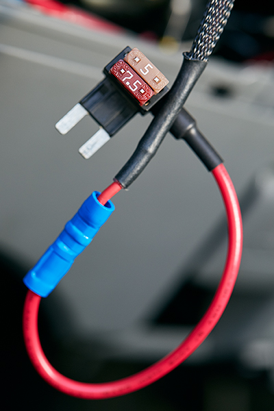
I used to have a pre-built Bussmann box that I bought off eBay that came with the 16 gauge but swapped it for a SPOD. Many of your Bussmann wiring connection questions can be answered with this 6-part article by Bodenzord

The AOB switch wires are like 20 or 22 ga. But the relay/switch wire of Bussman is 16 ga may be. I am thinking of running additional 20/22 ga wire through the grommet up to the bussman instead of running the fatter 16 ga wires from bussman down through the grommet ? Any concerns? The is the Red/Yellow wire.

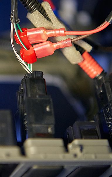
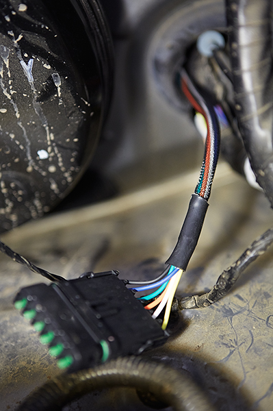
Running the smaller gauge wires through the grommet to the engine bay is the better option because you can fit more wires through your conduit. Problem is the butt connectors come in 20-18 gauge and 16-14 gauge. I wanted 5 switches so I was going to build a harness similar to the one referenced in Bodenzord's website above - part 5 so I could mate the smaller gauge wiring with the larger 16 gauge that came with the pre-built Bussmann. It's also nice too because you can quickly disconnect the switch harness from the engine bay if you were ever going to remove or modify your wiring.

2015-07-30_SwitchHarness_Z2A3694_WithText_web800.jpg


2015-07-31_SwitchHarness_Z2A3761_web600.jpg


I am also thinking of installing a 1/4 in dia channel/tube/conduit through the grommet and then run the wires through it.

Next in terms of the connecting the other AOB switch wires - where can i find the ignition on 12V power supply point to connect the green/yellow wire? I want the Rigid lights to be usable only when engine is on.

Same question about the Blue/Yellow wire that supplies lights to the switches. Where do I locate the connection points?

Here is how Bodenzord did his switch wiring in part 6. You will need to tap into the fuse box using THIS.

2015-10-29_TacomaSwitchPanel_Z2A6113_web600.jpg


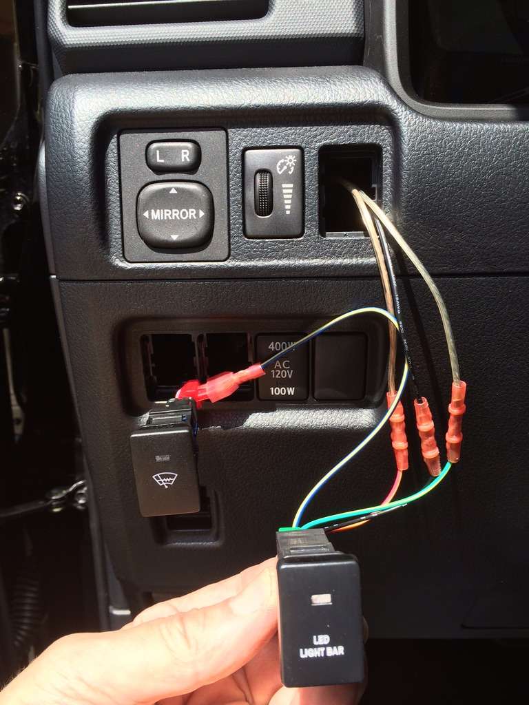
To wire the switches, he tapped into the illumination circuit from his VSC switch.

2015-07-31_SwitchHarness_Z2A3741_web600.jpg


Also refer to [MENTION=103267]Saker[/MENTION] build if you are using AOB switches HERE. He tapped into the wiper warmer switch.

dpja.jpg


or you can reference [MENTION=56922]NoOneBetter[/MENTION] build HERE. He tapped into the windshield heater switch using posi-taps.

25667574804_5f572d15ba_b.jpg


I am clueless about electrical wiring under the dash. If there are pictures that somebody can point me to about these connection points, it would be awesome.

the AOB diagram also talks about installing a 1A diode for newer cars??

Lastly how do I get the plastic cover under the steering wheel off to access all the wiring and put the switches in

many many thanks
I don't think you need a diode except for special situations. The references above do not mention diodes, but the electrical experts may need to jump in on this one.

Lastly, these links will help you with removing the trim panels that you may need for your switch wiring:
Driver Knockout Panel
Driver Kick Panel
Driver's A-Pillar
Center Console
 
Last edited:
^ that's a detailed response. [MENTION=128325]cutty01[/MENTION] boom you can drop the mic and walk off...
 
To wire the switches, he tapped into the illumination circuit from his VSC switch.

2015-07-31_SwitchHarness_Z2A3741_web600.jpg

[MENTION=128325]cutty01[/MENTION] - Great job with detail here!

One note for OP:
I have had to fix countless wiring issues because people have used these type of connectors. They are crap.
 
[MENTION=128325]cutty01[/MENTION] - Great job with detail here!

One note for OP:
I have had to fix countless wiring issues because people have used these type of connectors. They are crap.

The most common thing I have seen is people using the wrong kind of connector on the wrong wire (they are sized differently) and cutting the actual wire up), additionally they are not that great even when installed correctly.

They are very hit and miss from my experience...
[MENTION=128325]cutty01[/MENTION]

Out of curiosity why does it look like that fuse tap is running two fuses inline?
 

Members online

Forum statistics

Threads
278,310
Messages
3,554,078
Members
248,016
Latest member
Advally Service

Trending content

Back
Top