High beam indicator wire under dash

bittwiddler

New member
Before I tap into things and possibly break something I wanted someone to double check a few things for me.

I'm trying to wire up a switch for some front lights so it only operates when the high beams are on so I'm looking for a trigger line under the dash for the high beams only. I could run a wire from the lights but it seemed like there had to be something under the dash to indicate it already. Note this won't power the lights themselves but will just be the input to a relay

Based upon the diagram below from nashman's files it looks like the light green wire, pin #5, on connector F9 will indicate whether the high beams are on. Am I reading this correctly and does this seem like a safe line to tap into or will I end up causing other problems if I do this?

headlight.jpg
 
Register to hide this ad
I'd imagine [MENTION=65614]Antman[/MENTION] can chime in on this one - he's been balls-deep in the factory wiring probably more than all of us put together.
 
I'm far from an EE, but I think you're right in proceeding carefully here. If you tap the line between the headlight switch / high/low beam selector and the Main Body ECU, you're interfacing directly with the ECU - which isn't necessarily a good thing given the sensitivity and price of the ECU. I think that's why they use a relay on the headlights (and lots of other stuff) that's triggered by the signal from the ECU - but not actually driven by the ECU. The ECU triggers the relay and the relay is what switches the load that's actually supplied by an independent source.

I'm dealing with the same thing right now - http://www.toyota-4runner.org/5th-g...uestion-negative-switched-headlights-not.html
 
It will, but recognize that it is a GROUND signal, not 12V+
Toyota loves those ground switched lines, don't they. Thanks for the info

I'm far from an EE, but I think you're right in proceeding carefully here. If you tap the line between the headlight switch / high/low beam selector and the Main Body ECU, you're interfacing directly with the ECU - which isn't necessarily a good thing given the sensitivity and price of the ECU. I think that's why they use a relay on the headlights (and lots of other stuff) that's triggered by the signal from the ECU - but not actually driven by the ECU. The ECU triggers the relay and the relay is what switches the load that's actually supplied by an independent source.

I'm dealing with the same thing right now - http://www.toyota-4runner.org/5th-g...uestion-negative-switched-headlights-not.html

Well I was planning on sending the output of that connection to the ECU into a relay also but I understand your point about proceeding carefully. I was hoping there would be an easy way to tap a signal under there but maybe I really just need to run a wire all the way up front to the headlight
 
Toyota loves those ground switched lines, don't they. Thanks for the info


Well I was planning on sending the output of that connection to the ECU into a relay also but I understand your point about proceeding carefully. I was hoping there would be an easy way to tap a signal under there but maybe I really just need to run a wire all the way up front to the headlight

Woah. You can use a relay look at 12volt.com for wiring up a negative relay. It will just take a extra relay to convert it to a positive one. Very easy to do.
 
Toyota loves those ground switched lines, don't they. Thanks for the info

Well I was planning on sending the output of that connection to the ECU into a relay also but I understand your point about proceeding carefully. I was hoping there would be an easy way to tap a signal under there but maybe I really just need to run a wire all the way up front to the headlight

I weighed out the same issues and to be safe, I used my trigger from the high beam circuit at the light harness to avoid any issues, also my relays are located in the engine compartment anyway.
See the following: http://www.toyota-4runner.org/5th-gen-t4rs/164966-led-light-bar-install-2014-toyota-4runner.html


Hope this helps
 
Don't obsess too much about the Body ECU here. While there are some computer functions with circuits like door locks and windows, for the headlights the only thing that goes on in there is cross connection from one bundle of wires to another, just straight copper traces from Wire A in Plug X to Wire B in Plug Y. If it's a non-DRL rig, the circuit is brute simple no matter where you tap, just so long as you don't ground what should be 12V+ or vice versa--that's never good. It's all dumb relays, not a single semi-conductor on the page. The only exception is the auto-off section in the dash gauge console, so stay away from the red/yellow wire that connects to that.

The DRL circuit is a little more sensitive, but the diagram shown is NOT from a DRL circuit, as that doesn't go through the Body ECU at all except for the main power connections. The control switching all goes to the DRL relays, one of which is actually computerized, sort of. If the OP has DRL's and is using a non-DRL circuit diagram, then he has bigger problems and my comment does not apply. He doesn't give his year, so I can't be positive which he has.

I can't imagine why you would need a second relay just to deal with a ground switched circuit. You just connect the other side of the relay coil to a key-on power source and let the ground switching headlight switch do its thing. There has to be something else going on in there, i.e. a component that is polarity sensitive (LED's), not a simple relay that can be wired either way. If the aux lights are LED's, that makes no difference, as that is the power side of the relay and we are only concerned with the coil side.

Both EWD's are attached. My comment was not made lightly. It's fine to use that wire as a (ground-side) relay coil input for an aux light on a DRL truck. If you want to disagree, please provide an electrical reason so I can refute it.
 

Attachments

Last edited:
Don't obsess too much about the Body ECU here. While there are some computer functions with circuits like door locks and windows, for the headlights the only thing that goes on in there is cross connection from one bundle of wires to another, just straight copper traces from Wire A in Plug X to Wire B in Plug Y. If it's a non-DRL rig, the circuit is brute simple no matter where you tap, just so long as you don't ground what should be 12V+ or vice versa--that's never good. It's all dumb relays, not a single semi-conductor on the page. The only exception is the auto-off section in the dash gauge console, so stay away from the red/yellow wire that connects to that.

The DRL circuit is a little more sensitive, but the diagram shown is NOT from a DRL circuit, as that doesn't go through the Body ECU at all except for the main power connections. The control switching all goes to the DRL relays, one of which is actually computerized, sort of. If the OP has DRL's and is using a non-DRL circuit diagram, then he has bigger problems and my comment does not apply. He doesn't give his year, so I can't be positive which he has.

I can't imagine why you would need a second relay just to deal with a ground switched circuit. You just connect the other side of the relay coil to a key-on power source and let the ground switching headlight switch do its thing. There has to be something else going on in there, i.e. a component that is polarity sensitive (LED's), not a simple relay that can be wired either way. If the aux lights are LED's, that makes no difference, as that is the power side of the relay and we are only concerned with the coil side.

Both EWD's are attached. My comment was not made lightly. It's fine to use that wire as a (ground-side) relay coil input for an aux light on a DRL truck. If you want to disagree, please provide an electrical reason so I can refute it.


I don think I was totally clear you do need two relays. one to power the switch the negative relay. one that the switch triggers for the lights the switch controls. two relays. A regular wwitch does not need the neg relay to power the switch as you usually get it from a ignition or constant power source. Makes figuring out what you need when building a relay box/ fuse box under the hood easier so you dont go theough all that trouble to just have extra relays under the dash.
 
I weighed out the same issues and to be safe, I used my trigger from the high beam circuit at the light harness to avoid any issues, also my relays are located in the engine compartment anyway.
See the following: http://www.toyota-4runner.org/5th-gen-t4rs/164966-led-light-bar-install-2014-toyota-4runner.html


Hope this helps

I used Saker's idea, ordered a 9005 extension from Amazon and tapped into the power wire on the extension... Plugged this extended unit into the High beam and that runs into the wiring harness i have from the my power distribution unit (and relays) to the switches via wiring loom.
 
I don think I was totally clear you do need two relays. one to power the switch the negative relay. one that the switch triggers for the lights the switch controls. two relays. A regular wwitch does not need the neg relay to power the switch as you usually get it from a ignition or constant power source. Makes figuring out what you need when building a relay box/ fuse box under the hood easier so you dont go theough all that trouble to just have extra relays under the dash.

I'm confused here; couldn't you just source a Normally Closed Relay vs. typically found Normally Open Relays? Thus you wouldn't need a second relay? Or am I understanding your descriptionwrong?
 
I don think I was totally clear you do need two relays. one to power the switch the negative relay. one that the switch triggers for the lights the switch controls. two relays. A regular switch does not need the neg relay to power the switch as you usually get it from a ignition or constant power source. Makes figuring out what you need when building a relay box/ fuse box under the hood easier so you dont go theough all that trouble to just have extra relays under the dash.

I don't see why you need a negative relay. You can still get your switch power from a key on source, run it through the relay coil and then the other side gets ground from the headlight switch. Why do you need a negative relay in the OP's case? What am I missing?
 
I don't see why you need a negative relay. You can still get your switch power from a key on source, run it through the relay coil and then the other side gets ground from the headlight switch. Why do you need a negative relay in the OP's case? What am I missing?

The highbeam signal under the dash is a negative trigger. You woukd use this to power the switch. Ehen the high beams come on the switch is powered. One relay negative trigger to power swtich.


The switch controls the lights ultimately when the switch has power you can press the button and the different lights woukd come on. The switch controls a pos relay to power any light.

So in closing a neg triger relay powers the switch, then a positive relay after the switch to power the lights.

Comes in very handy for the front lights of a vehicle. Your lights, lightbar, bars up front will not work unless you are using the highbeam. Not all do this. Works well if you want to be able to run your lights on backroads and be able to flick them off along with your brights with the pull of the higbeam stalk. Also the ignition has to be on as well to function.

I have my circuit/relay box which I have yet to install under the hood. It is prewired for this circuit with the fuses and relays in a bussman box, my lights are going to be wired as follows. Highbeams/Switch -> Roof Led Lightbar, Highbeams -> Switch Grill Led Lightbar, Ignition -> Switch Side Led Lightbars, Ignition -> Switch Rear Led Lightbars, Igniton -> Switch Rock Lights, 12V Contant -> Fuse -> Strut Switch Under Hood Led, my other electricals in the bussman are as follows for reference Ignition -> Fuse Radar Detector, Ignition -> Fuse Front Recording Video Camera, Constant -> Switch Engel 45, Ignition -> Fuse CB/HAM Radio. Constant -> Switch Spare Battery, in a Bussman 10 Relay Box. You do not have to do this to way to wore up the lights it is just one way.

Alternatively you could do Ignition -> Switch to control Light, or Constand -> Switch ti.

Athough it is truley more like - Highbeam -> Neg Relay -> Fuse -> Switch -> + Relay -> Fuse -> Lightbar. All other circuits follow similar means even the + Ignition/Constant -> Fuse -> Switch -> + Relay -> Light or whatever. I hope you can follow. If not again look at 12volt.com to see how these are wired.

Note: Full disclosure, i did not build my Circuit/Relay Box Skygear on Tacoma Forums did. I looked at other then looked at doing myself cause of how I wanted the items to work and the connections I wanted he had the best solution and built better than I could for same or less than other solutions. It aint cheap but easy to track down if I have any electrical issues.

Excuse me if I got some of it backwards I didnt see but someone will chime in and correct it. I do have a TBI and small detail do escape me as well as my memory is shot I barely remember this stuff. Also, to OP if you use the ground on the highbeam on the relay it is not the correct way of wiring it, will it work yes yet can cause issues.

 
Last edited:
Excuse me if I got some of it backwards I didnt see but someone will chime in and correct it. I do have a TBI and small detail do escape me as well as my memory is shot I barely remember this stuff. Also, to OP if you use the ground on the highbeam on the relay it is not the correct way of wiring it, will it work yes yet can cause issues.

There is absolutely nothing wrong with doing it the simple way. My fogs have been wired to come on with the lows (the law in NJ at the time) since 1999 with one relay.

I didn't say your way wouldn't work, it's just not needed. Plenty of light manufacturer's recommend doing it my way in the case of negative ground triggers, including Hella who made mine. The factory fogs are wired that way.
 
Pnow after typing all that. I am now unsure of what I said. I may be getting the type of circuit aa bit backwards. Because you could also have the following:


+ Input either Con/Ign to SPDT Switch
+ Input from switch into relay 86
- Trigger from Highbeams 85
+ 12Volt to 30
+ 12Volt to Lights 87

Now I even question myself. Darn Brain. Please excuse me if I am inccorect something I am missing.
Or:

Relay:
87
----------
- -
86 - - 85
- -
----------
30

Working from the relay
30 - Fuse -> 12V Battery
87 - Lights
86 - Negative Trigger High Beam or Low Beam
85 - 1Amp Diode -> Switch
 
Last edited:
There is absolutely nothing wrong with doing it the simple way. My fogs have been wired to come on with the lows (the law in NJ at the time) since 1999 with one relay.

I didn't say your way wouldn't work, it's just not needed. Plenty of light manufacturer's recommend doing it my way in the case of negative ground triggers, including Hella who made mine. The factory fogs are wired that way.

Oh, fog lights indeed I woukd have come on with just the low normally. As I could see situations where it could be blinding to oncoming teffic. Though If I with 30000 + lumens of light bar forget to hit my highbeam off to oncoming traffic the other other driver is like holy crap the sun....
 
Oh, fog lights indeed I woukd have come on with just the low normally. As I could see situations where it could be blinding to oncoming teffic. Though If I with 30000 + lumens of light bar forget to hit my highbeam off to oncoming traffic the other other driver is like holy crap the sun....

Lows, highs, full-time, key on, 55w or 1500w--it doesn't matter, you still only need one relay.
 
Last edited:
Lows, highs, full-time, key on, 55w or 1500w--it doesn't matter, you still only need one relay.

That part had nothing to do with multiple relays. Normal wiring up just power froma switch is definitely one relay. As you where discussing. Ie

12v Ignition powers -> Fuse -> SPDT Switch -> Relay -> Fuse -> Light.

You turn the car on flip the switch and the light turns on. Nothing to do with negative triggers or such and didnt go into wiring that relay again look at 12volt.com for instructions how to.

The dilemnia is the negative relay, also wattage is no the issue but Amperage is. Most 12V and you are at 30 Amp Maximum. Like I said above even with a negative trigger (The headlight, highbeams send out a negative signal to from the switch/ecu to power on.) you can wire up a single relay to do so as I stated above. Though putting a diode inline on the trigger may be good measure for no feedback. Now the issue here is the ground the ground is the trigger not a permanent grounded location. I dont remeber exactly why I am remembering something like this but there is some circumstance where you need to you two relays also spoken above. I will consult some of my friends with more experience and much better memories about this.
 
That part had nothing to do with multiple relays. Normal wiring up just power froma switch is definitely one relay. As you where discussing. Ie

12v Ignition powers -> Fuse -> SPDT Switch -> Relay -> Fuse -> Light.

You turn the car on flip the switch and the light turns on. Nothing to do with negative triggers or such and didnt go into wiring that relay again look at 12volt.com for instructions how to.

The dilemnia is the negative relay, also wattage is no the issue but Amperage is. Most 12V and you are at 30 Amp Maximum. Like I said above even with a negative trigger (The headlight, highbeams send out a negative signal to from the switch/ecu to power on.) you can wire up a single relay to do so as I stated above. Though putting a diode inline on the trigger may be good measure for no feedback. Now the issue here is the ground the ground is the trigger not a permanent grounded location. I dont remeber exactly why I am remembering something like this but there is some circumstance where you need to you two relays also spoken above. I will consult some of my friends with more experience and much better memories about this.

You have relays to control any amperage. The triggers are on the coil side which have minimal amp load regardless of the size of the load. My point is the OP has no need of whatever it is you can't remember.
 
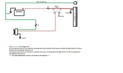
This setup has worked for mine without issue.
 

Attachments

  • Light circuit _01.JPG
    Light circuit _01.JPG
    93.4 KB · Views: 2,166

Members online

No members online now.

Forum statistics

Threads
278,306
Messages
3,554,045
Members
248,016
Latest member
Advally Service

Trending content

Back
Top