

RAD4Runner
Senior Member
(Revised using different photo host because Google Photos Links Got Messed Up)
Why this mod?
Because my horn sounds like Mickey Mouse with his balls caught in a mouse trap - LOL!
Why?
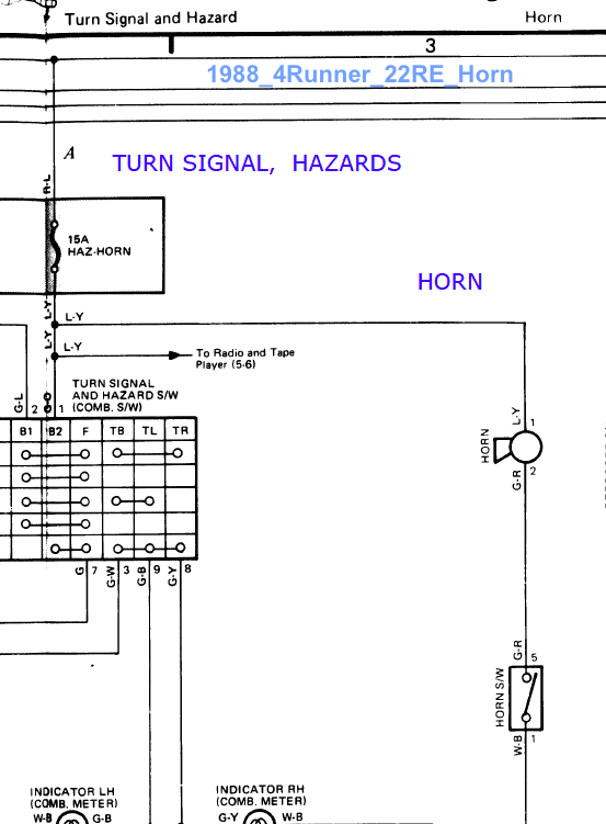
Because the current for the first gen pickup and first gen 4Runner runs from battery, to horn, TO CABIN, TO HORN BUTTON ON STEERING WHEEL, back to engine compartment, to ground point on inner fender; No different from the convoluted path of headlight and starter relay current. This causes lots of voltage drops along the wiring and horn button, and subjects horn button to full load current; worse if one upgrades to higher power horn.
This mod will fix that, and allow us to put higher power horn(s) if we want.* I think this Horn Relay Retrofit will apply to all First-Gen and earlier which do not have horn relay. (I don't know about the 1989 pickup.)
Yes, I will still inspect/fix the sliding pin/contact in the steering column.
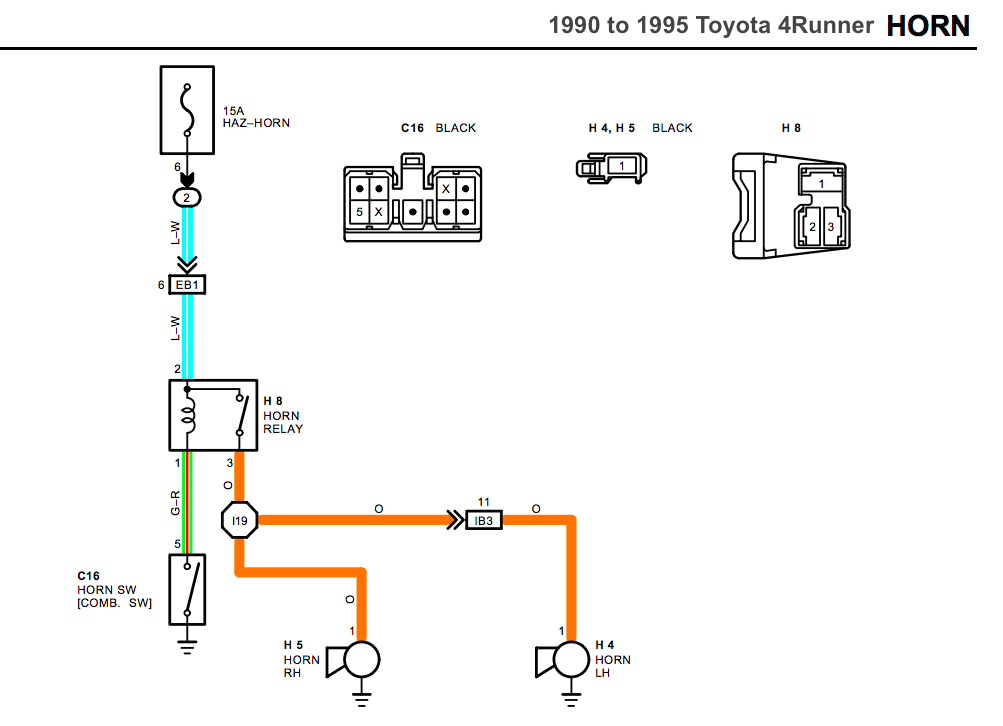
Second gen 4Runner has horn relay to carry horn load current:
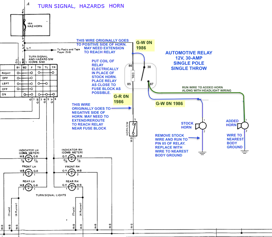
HERE'S HOW I WIRED MINE:
Schematic explains most details.
IF you want to add an outrageously loud and powerful horn, I suggest you power pin 30 of relay with separate fused line from battery.
OVERVIEW AND GENERAL WORK AREA IS UNDER RIGHT -SIDE FENDER, FRONT CORNER (BELOW):
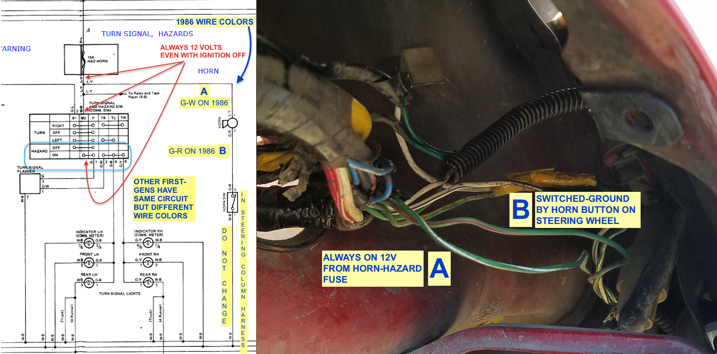
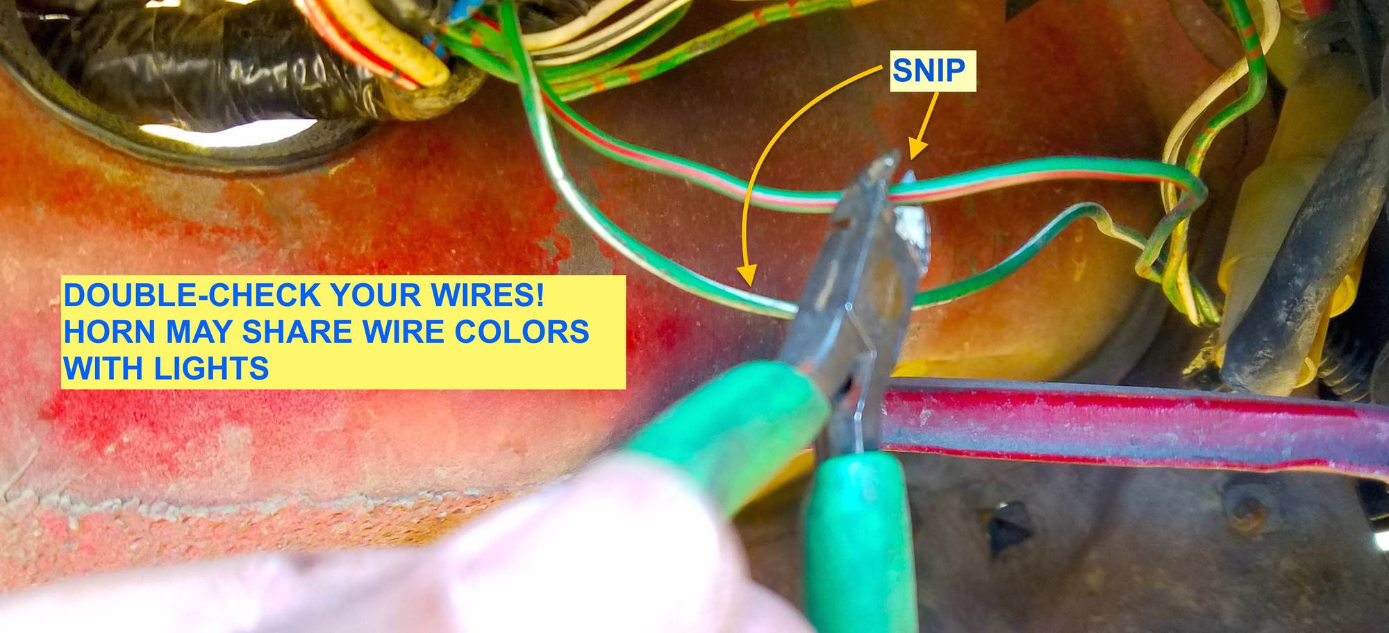
SNIP WIRES "A" AND "B" AT POINT WHERE IT WOULD BE EASY TO SPLICE / SOLDER.
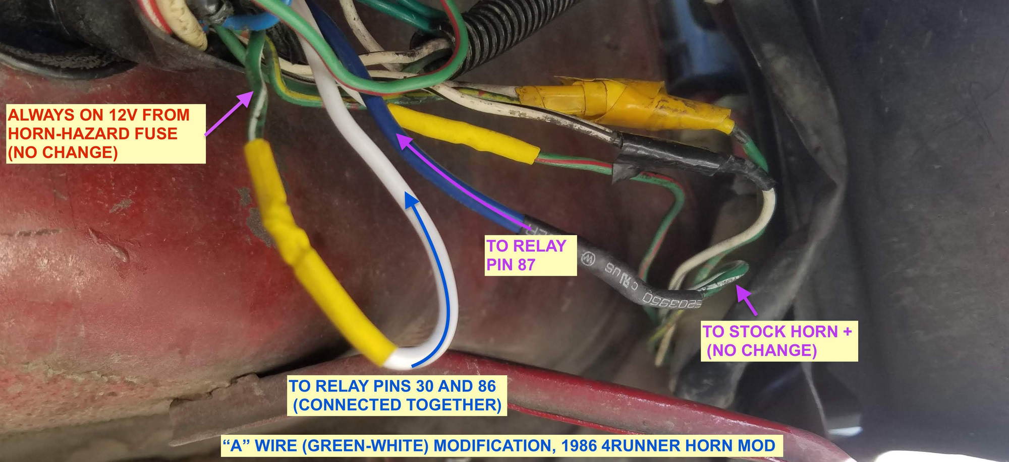
SPLICE EXTENSION WIRES TO REACH RELAY IN ENGINE COMPARTMENT:
I put mine forward of the fuel injector resistor bank. Two feet of wire per extension worked well for me.
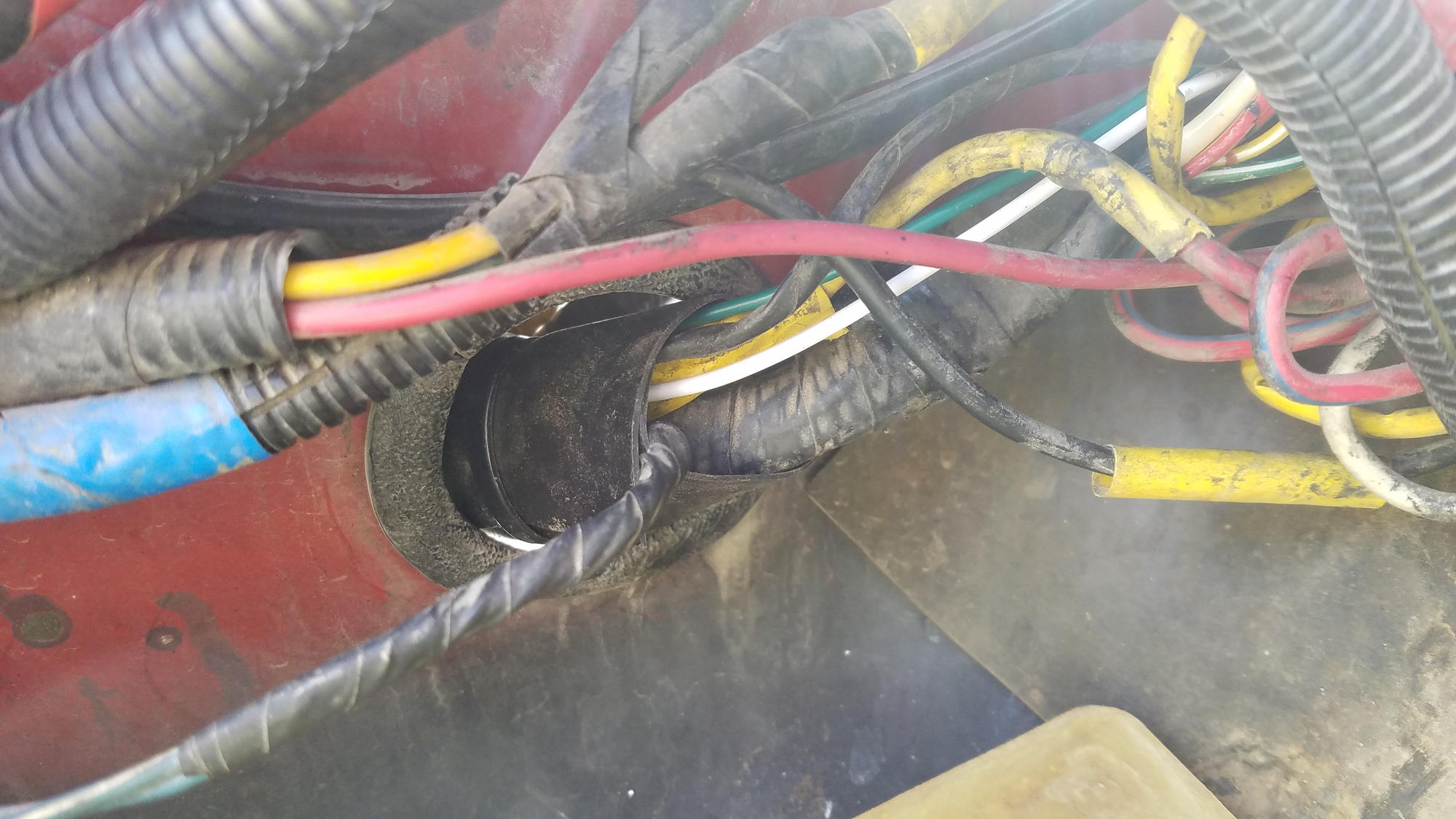
I LINED TOP SURFACE OF WHEEL-WELL WITH THIN RUBBER SHEET TO PROTECT WIRES.

I ALSO WRAPPED WIRE BUNDLE THROUGH THE GROMMET WITH SAME RUBBER SHEET FOR EXTRA PROTECTION.
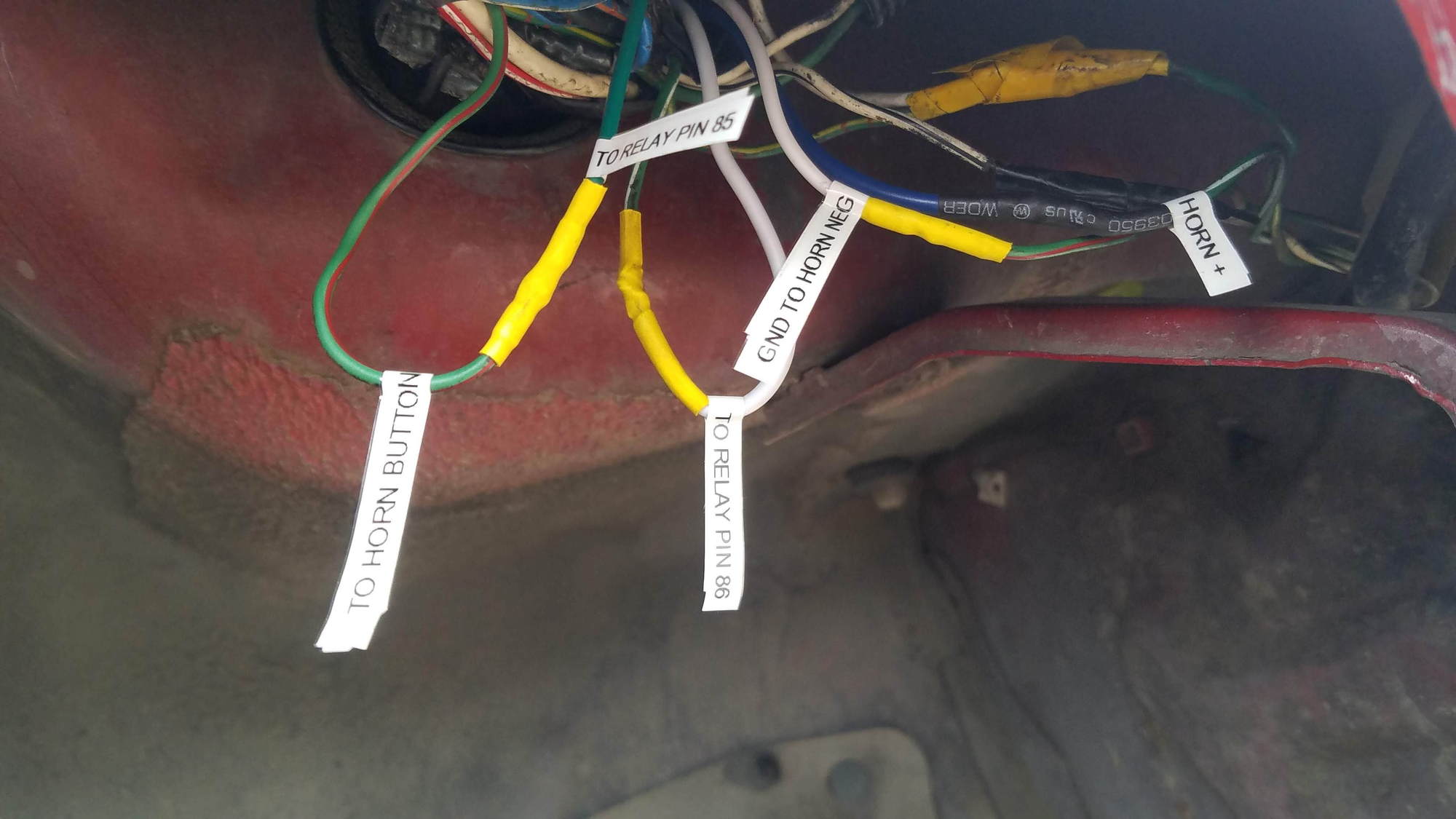
I did not bother buying wires with stock colors so i just labeled new wires
ALSO ON YOTATECH HERE
Why this mod?
Because my horn sounds like Mickey Mouse with his balls caught in a mouse trap - LOL!
Why?
Because the current for the first gen pickup and first gen 4Runner runs from battery, to horn, TO CABIN, TO HORN BUTTON ON STEERING WHEEL, back to engine compartment, to ground point on inner fender; No different from the convoluted path of headlight and starter relay current. This causes lots of voltage drops along the wiring and horn button, and subjects horn button to full load current; worse if one upgrades to higher power horn.
This mod will fix that, and allow us to put higher power horn(s) if we want.* I think this Horn Relay Retrofit will apply to all First-Gen and earlier which do not have horn relay. (I don't know about the 1989 pickup.)
Yes, I will still inspect/fix the sliding pin/contact in the steering column.
Second gen 4Runner has horn relay to carry horn load current:
HERE'S HOW I WIRED MINE:
Schematic explains most details.
IF you want to add an outrageously loud and powerful horn, I suggest you power pin 30 of relay with separate fused line from battery.
OVERVIEW AND GENERAL WORK AREA IS UNDER RIGHT -SIDE FENDER, FRONT CORNER (BELOW):
SNIP WIRES "A" AND "B" AT POINT WHERE IT WOULD BE EASY TO SPLICE / SOLDER.
SPLICE EXTENSION WIRES TO REACH RELAY IN ENGINE COMPARTMENT:
I put mine forward of the fuel injector resistor bank. Two feet of wire per extension worked well for me.
I LINED TOP SURFACE OF WHEEL-WELL WITH THIN RUBBER SHEET TO PROTECT WIRES.
I ALSO WRAPPED WIRE BUNDLE THROUGH THE GROMMET WITH SAME RUBBER SHEET FOR EXTRA PROTECTION.
I did not bother buying wires with stock colors so i just labeled new wires
ALSO ON YOTATECH HERE
Last edited:


