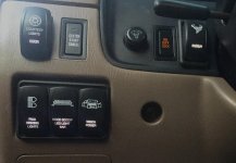
How Can i Wire the dash dim switch to AUX lights?

Using this type of switch, should hooking up wire #3 to the green and #4 to white/green yield the desired effect of having the switch LED dim along with the factory switches/dash lights? Thanks

If by Wire # 3 you mean the one labeled Red 2, then yes you are correct.
 
If by Wire # 3 you mean the one labeled Red 2, then yes you are correct.

Correct, as in, if it is going to work, that is how you do it. Dimming LED's is not always going to work, so if the switch is not designed to dim, it may not work well. I don't see anything on the wiring diagram that says the thing is meant to dim.
 
FWIW all of the switches with LEDs I have installed from OTRATTW dim just fine and are wired to the dimmer switch as previously discussed.
 

Attachments

  • image.jpg
    image.jpg
    136.4 KB · Views: 4,526
Green Wire

Hey All!

Been lurking here for over a year now, just recently started doing some work on my 1996 4Runner.. (Hope to post some of that work soon.)

Right now I'm putting in some AutoMeter gauges, and I've been reading this thread and every other thread I can find to see about how I can get the gauge lights hooked up to work with my factory dimmer. Nice thing about the AutoMeter gauges is that they have a separate bulb that isn't tied in to the common ground or anything on the gauge, so they should work fine with the factory dimmer, even though it sits on the negative side of the bulbs..

Anyways, to my question. I see that there are three wires to the factory dimmer, one is the ground, one is from the negative side of the dash lights, and then there is the solid green line that is power from the headlight switch. But I can't figure out why the switched power is run down to the dimmer. I mean the dash lights all pull power directly from the headlight switch, then their negative leads go down to the dimmer to get dimmed.. I can't see a reason why the dimmer needs the switched power to go to it.. Unless, maybe there is an optional dimmer that has it's own light or something and the wire is just there for that?

I'm thinking that I can just tie into the two wires in the dimmer to power the lights on my gauges. (And that is what the folks in this thread seem to be saying) But, I just wanted to understand the purpose of that green wire running to the dimmer before I start hacking into it. I mean does the rheostat somehow need power on one leg so that it can add resistance on the other leg? (I've never heard of that, but there is a lot I don't know)

Thanks!!
 
Hey All!

But, I just wanted to understand the purpose of that green wire running to the dimmer before I start hacking into it. I mean does the rheostat somehow need power on one leg so that it can add resistance on the other leg? (I've never heard of that, but there is a lot I don't know)

Thanks!!

I'm not 100% on this, but starting in the 80's OEM's starting using a sort of voltage divider in lieu of a rheostat. Since then I believe they are simply using a solid state type of rheostat which does require power to operate.
 
I'm not 100% on this, but starting in the 80's OEM's starting using a sort of voltage divider in lieu of a rheostat. Since then I believe they are simply using a solid state type of rheostat which does require power to operate.

Thanks for the quick reply! Based on what you said about a voltage divider, I did some more reading and see that the Toyota dimmer isn't a rheostat, it is a potentiometer, or as you said a "voltage divider".. I still have no idea why a potentiometer requires power, instead of just having two legs going through a variable resister.. But that is ok. Everyone on-line says that potentiometers work that way, and I trust the internet.. :)

Anyways, I feel more comfortable taping into the wires for my gauge lights now.. I like that I can grab the power right from the dimmer wiring. I was looking at grabbing the power from the wiring harness that is behind the gauge cluster, but I'd rather not tie in there if I don't have to.. One nice thing about the wiring to the dimmer switch is that the little modular plug uses spade connectors, so I think I'm going to make a very tiny set of male-female space connectors to go between the factory plug and the dimmer, and this is where I'll pull my power.. Which means I won't actually have to modify that section of my wiring harness..

I'll post some pictures once I've got it done.

Thanks again!

 
Thanks for the quick reply! Based on what you said about a voltage divider, I did some more reading and see that the Toyota dimmer isn't a rheostat, it is a potentiometer, or as you said a "voltage divider".. I still have no idea why a potentiometer requires power, instead of just having two legs going through a variable resister.. But that is ok. Everyone on-line says that potentiometers work that way, and I trust the internet.. :)

Anyways, I feel more comfortable taping into the wires for my gauge lights now.. I like that I can grab the power right from the dimmer wiring. I was looking at grabbing the power from the wiring harness that is behind the gauge cluster, but I'd rather not tie in there if I don't have to.. One nice thing about the wiring to the dimmer switch is that the little modular plug uses spade connectors, so I think I'm going to make a very tiny set of male-female space connectors to go between the factory plug and the dimmer, and this is where I'll pull my power.. Which means I won't actually have to modify that section of my wiring harness..

I'll post some pictures once I've got it done.

Thanks again!

It has always bothered me that Toyota calls the dimmer a rheostat when it is obviously a pot (potentiometer). The only relevant difference is that they have a better idea of the brightness scaling with a pot compared to a rheostat as the actual exact load can be uncertain. In other words, a pot will always give you 6 volts (assuming 12V total) at 50% position, with a rheostat it depends on the load and the resistance of the rheostat. At only ONE given total load resistance, will the rheostat also pass half the input voltage at the half point on the dial.
 
Last edited:
The 3rd gen Rheostat is a 3 terminal switch. The are as follows

Power to Terminal 1
Ground to Terminal 3
Negative side of light to Terminal 2

The lights have 12V all the time the headlight switch is on park or headlights. The Rheostat varies the resistance to ground.

Could you tell me which pins go where? what is pin1, 2, and 3? possibly a labeled drawing/picture would be nice!
 

Members online

Forum statistics

Threads
278,316
Messages
3,554,113
Members
248,016
Latest member
Advally Service

Trending content

Back
Top