

MTD
New member
AEM F/IC-6 Install & Tuning
By: MTD (2015)

By: MTD (2015)
TLDR: This is a new, cheaper, and more efficient way to tune the 5VZFE that has the TRD Supercharger. The guide currently covers install, but will be expanded to cover tuning and other related topics as well.
INTRO:
Alright guys before we get started with the install and how to tune this I wanted to give a brief overview of why someone would select this over the other options there are on the market currently. I may have jumped the gun and alienated some people to the idea of this tuning system and I would like to apologize for that. What I will attempt to do now is lay out the facts in a clear and organized manner and allow you (the end user) to make the choice for yourself.
What- The AEM F/IC-6 is a all in one tuning computer that allows you to tune your vehicle with either stock, larger injectors, meth, or any other form of fuel enrichment (race gas). I has an on board MAP (manifold absolute pressure) sensor that reads the absolute pressure that your engine see's. You then use the F/IC-6 to skew o2 and AFR values entering your stock computer and add fuel for both part throttle, and WOT boost enrichment. This system is an excellent choice to be used with the TRD Supercharger, and is much more flexible and affordable than other systems that are available on the the market for our trucks.
Why- So why would you use this system instead of the other 'tried and true' products for our vehicles? There are many reasons, the first is being:
- Compatibility - The AEM F/IC 6 has the capability to provide both open and closed loop enrichment to all model years of the 5VZFE. Which is critical for engine life and longevity
- Ease of Use - There is a large following in every facet of motorsports for the AEM brand and because of that there is a ton of 3rd party support.
- Software - AEM has done a great job of laying out the software for the F/IC and making it intuitive for the beginner to the pro
- Datalogging - On top of this the F/IC works as a datalogger which is invaluable for creating and modifying tunes when working alone. You can then import your log file into AEMdata, which is an immensely powerful program to read and track data logs.
- Tuning Control - Allows you to retard timing effectively, in addition to controlling fuel delivery, maf, and o2 skewing.
- Price - The Final point and the icing on the cake. A AEM F/IC install can be done for the relatively low cost of $380 for a BRAND NEW unit. No more need to pick up someone's sloppy seconds to tune your truck!
Overview video:
How- This is the fun part, and the reason you are here. I have spent the last couple months researching, and about 2 days of puttzing I have the process for installing the AEM down. This thread after the process is laid out will serve as my tuning journal as well as a place for people who are installing and tuning to ask questions that are AEM specific. The process is fairly easy, first will be a resource section that helps the end user determine what vehicle they have and what install procedure they will need to follow. Following that will be the optional step of building your own piggy back or jumper harness. Next will be install followed close after by the tuning section. Enjoy!
Compatibility:
The F/IC-6 is compatible with every fuel injected car on the market(up to 6 cylinders). There are some exceptions to every rule, but the 5VZFE is not one of them. This section will help sort out the small caveats that Toyota has built into the different model years of the 5VZ and help you to figure out which install procedure to follow. This tutorial will lay out any deviations from the F/IC install manual, and will include some tips, but will not walk through each wire step by step. The reason for this that Toyota changed wire colors and pinouts during the model years.
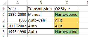
There are 2 important changes in the install process based on the model year and features. The wiring harness and the O2 sensor types changed over the years and bellow is a matrix to determine which you have on your Runner. Make sure that you are positive on what your vehicle is equipped with otherwise it will cause problems further into the install.
Wiring Harness- The wiring harness type was mainly model year dependent, but early on there were some variations between the auto’s and the manuals. I don’t have an experience with the harness listed as type B, and I don’t think the AEM harness works for the model years that are different.
I am working on a tutorial to go along with the instal that tells you how to make a piggyback harness from an old ecu and plugs. It's about $50 in parts and then it just costs time to solder it up. This is what I am running now.
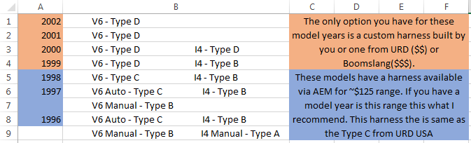
Need to confirm that AEM Harness is compatible ^^^^ You can check HERE.
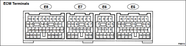
Type C
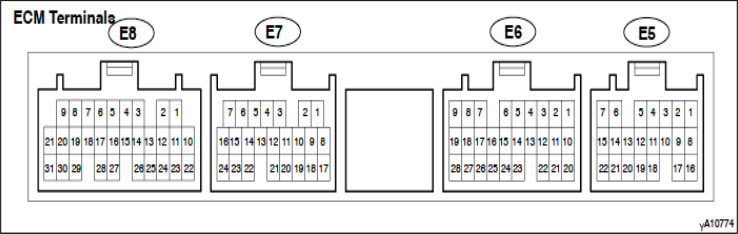
Type D
O2 Sensor Type- If you don't confirm the o2 type before instal there is a chance that you won't be able to tune the 4Runner because O2 skewing will not work. For those of you with the AFR style O2 the AEM is especially appealing when compared to the URD 7th because you can tune closed loop and part throttle boost with it.
3rd Gen 4Runner:
What you need:
I will do my best in this section to lay out everything that you will need and will want to install and tune this properly.
Reference:
- TIS Subscription - This isn't an optional thing, pay the $15 and download all of the manuals for your year. For installing the F/IC it is a requirement since Toyota changed pinouts so many times over the years. I have looked for free wiring diagrams on the internet and didn't find anything for my year (2000) there may be something out there for your year, but save yourself the trouble having these diagrams is wonderful for any electrical project. You can access the TIS page here.
- AEM F/IC Instal manual - I will let you know what you can ignore in it. It can be found here.
Parts:
- 30-1910 AEM F/IC-6 Universal - Don't get any other part number otherwise it may not work. It has to be the universal model.
- 30-4110 AEM UEGO Wideband Gauge - Can be any wideband, but this is the one that I am using and it works great.
- 1/4W 2.2K Resistor - For signal filtering on the cam circuit. This is a requirement, If you don't install this the truck will through a code for the cam circuit.
- 1/4W 10K Resistor - This is needed for O2 skewing for the narrow band trucks, if you have a 00+ you can disregard this. Also do not go on the AEM instructions for the 1k resistor, it will not work.
- 1/4" Heat Shrink
- Solder
- Zip Ties
- Donor ECU
- Matching ECU Plugs
__
OR
__
- Boomslang/URD/Other Extension Harness
Tools:
- Soldering Iron
- Wire Strippers
- Heat gun
- Propane torch
- Screw drivers
- Razor Blade
- E-Tape
- 8mm, 10mm, 12mm Sockets
- Helping hands (optional)
- Molex depin tool (sorta optional)
Basic Install:
The basic install is what you follow if you will be wiring this up directly to your stock wiring. This method is the cheapest and can be the least time consuming because there is no expensive harness to buy, and you won't be spending time building a harness. That being said I don't recommend it because if there is an issue with you wiring job, you can't go back to stock by simply unplugging the extension/piggyback harness. The AEM does come with a bypass plug that would allow you to remove the unit if you have problems, but depending on which wire is the culprit there is no guarantee that it will bypass it correctly.
- Get your F/IC manual.
- :rtfm: Learn it, read and become familiar with it, and if you have any questions consult the glossary in the back of the manual. Then if you still have questions feel free to ask them here.
- Now that you are all up to speed on the manual I will lay out the install process for you starting with what sensor type you should be wiring for. I suggest depinning the AEM Wiring harness so that there isn't just a bunch of wires flopping around that are not being used. Be careful if you attempt to depin the unused wires though because you could potentially wreck your harness. Here is a list of wires that are commonly mistanken:
A. MAG Crank and Cam sensors - All HAL sensor wires can be eliminated from the AEM harness. We will only need the MAG style sensor wires.
B. MAF sensor only - The 5VZFE doesn't have a MAP sensor so the wires for that can be eliminated
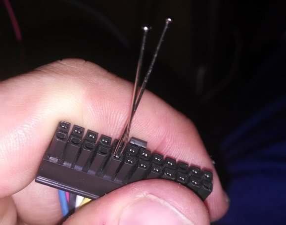
Here is a good video on how to depin the molex connector that AEM uses. If you have experience with computers this is the same process as depinning a mobo header.
Being the cheap a$$ I am I of course did not buy the depinning tool that they recommend, instead I just took a dremel and flattened horizontally the end of two pins and it worked like a charm.
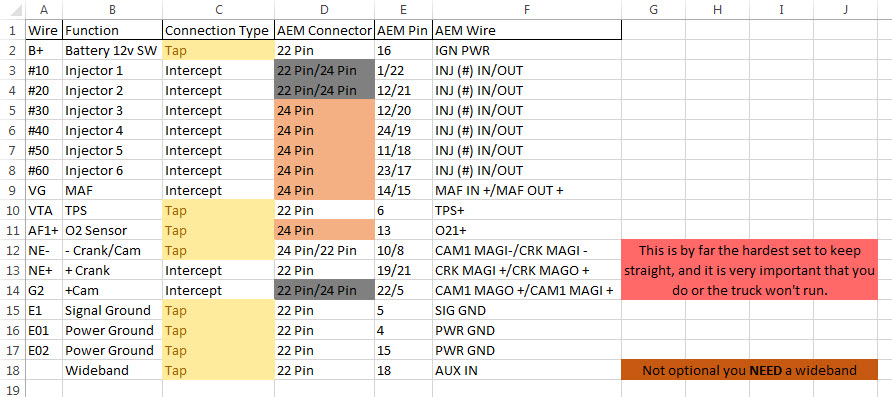
- For specific pins you will need to be looking at your "Engine Control" wiring diagram. The letters in the blue box are the function of each wire, the letter in the bubble is the connector, and the number beside it is the pin number. Below is a list of the abbreviations that designate wires that you will need to send to the AEM:
(Updated 8/18/15)
[*] Now the resistors can be done at the same time as the above step, but it isn't really important that it is since they are pretty independent of the actual wiring.
Cam Sensor Resistor: (Updated 12/25/15)
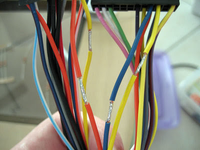
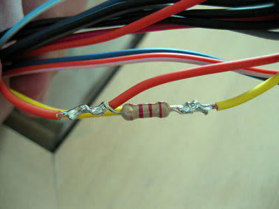
Toyota has a reputation of getting by with a very dirty signal with their sensor circuits, it could be to save cost or just because they can. Regardless to the reason because of this we need to add a low pass filter otherwise when we hook up the AEM the dirtiness (excuse my lack of knowledge on this I am not an EE lol) of the signals will be amplified and the truck will throw a code. Luckily this LPF can be simply taken care of by a 1/4W 2.2k resistor. You will need to bridge the CAM MAGI - and the CAM MAGI + with this resistor.
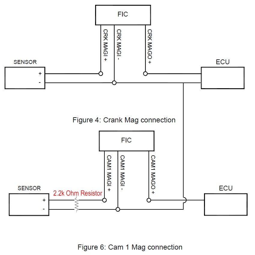
(Diagram Courtesy of Garret Curry)
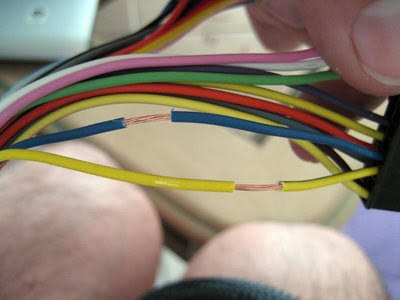
To bridge these I followed the method (Just the method use the wires and resistors I tell you) of this gentleman.
These next two pics show how the wires were carefully stripped with the razor blade. Take your time on this.
You now want to tin the bare wires. This means you want a coat of solder on the wires. Here's how they look:
Next you want to take the resistor and wrap the ends on each wire... and snip off the excess. Then solder the connection.
Now all you need to do is wrap this up with electrical tape and you're done!
O2 Sensor Resistor: Skip if you have a AFR Style O2 sensor truck. See the chart in the reference section if you are unsure.
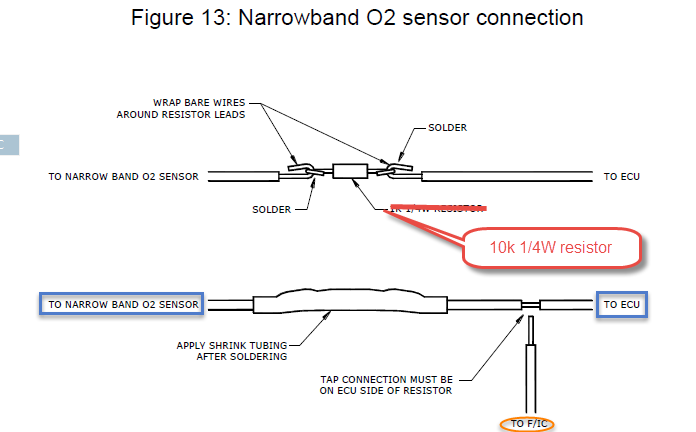
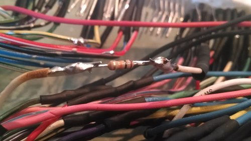
If you have a narrow band O2 4Runner you will need to do this step otherwise the O2 skewing will not work. Do not use the 1k resistor that AEM recommends in the install manual, for toyotas a 10K resistor is what we need. Make sure to solder it in on the sensor side of the harness ahead of the tap for the O2 skewing from the AEM. Here is a diagram of where to put it:
Here is what it looks like on the harness:
Last edited:

 arty:
arty:


