
neurotictim
New member
Okay, so I had a lot of response to this on one of the Facebook 4Runner groups, and I’ve finally found time to do a write up. This is not a difficult mod to do, it just requires patience and a reasonably steady hand with a soldering iron.
First thing you should know: If you do this, you will not be able to put normal light bulbs back in, as this mod requires permanent modification to the boards of the switches.
Second: These lights are wired to be “on” when the parking lights or headlights are on. This means that the LCD and switches will NOT be lit with the exterior lights off, and that’s how I wanted it. To do any more than this would require a lot more time and engineering than I wanted to put into this project, but you are welcome to jump off from here if you want. I feel like having the backlighting on when it’s bright outside is pointless anyway, but ymmv.
Third: This is an afternoon project, but plan for extra time because it’s always a good idea, and your 4Runner will be out of commission while you’ve got the HVAC out. Don’t try to start the truck without the HVAC plugged in – since the airbag indicator is located in the HVAC assembly, there’s a possibility starting it while unplugged will trip the airbag light, which (to my knowledge) has to be reset at the dealership.
Disclaimer: This writeup is intended as a guideline for modifying interior lights so that they are RGB LED driven. I am not claiming anything more than that this is the process I used, shortened for brevity, and that results may vary. Don’t blame me if you burn yourself, get flux in your eyes, etc., and don’t blame me if it doesn’t turn out exactly right the first time.
Things you’ll need:
Soldering iron / solder / flux and solder wick strongly recommended / heat shrink (especially small)
Screwdrivers / Dremel / black paint / cloth or electrical tape recommended
You’re going to need to order a few parts online.
First, you’ll need an RGB controller of some sort. Whether it’s IR remote controlled or via Bluetooth/WiFi, it needs to be 12v driven. I’ve used both of these and they work well.
https://www.amazon.com/gp/product/B01JS0KEBW/ - Wifi/App controlled
https://www.amazon.com/gp/product/B00AF5YOK2/ - IR remote, no app.
Second, you’ll need some LEDs and wire.
https://www.amazon.com/gp/product/B07FDW4M89/ - You won’t use 100 feet, but it’s nice to have on hand.
https://www.amazon.com/gp/product/B0777BQC1P/ - These aren’t strictly necessary, but nice to have handy as well.
https://www.amazon.com/gp/product/B01AUI4VR4/ - These are the LEDs I used to replace the orange triangle lights in the switches. I used white, but you could theoretically use any color you can want, as long as it’s 3mm. These are 3V and work just fine.
https://www.amazon.com/gp/product/B01C19ENFK/ - These are the RGB LEDs used to light up the rest. Note that they’re common anode, that’ll be important when we wire em up.
https://www.amazon.com/gp/product/B06Y5GC3VY/ - These are the resistors that regulate the voltage to the LEDs. I bought a big variety pack, but really you only need the 100 ohm, 150 ohm, and 180 ohm resistors, at 1W power. If you buy a variety pack you can experiment, but make sure they’re at least 1W rated.
https://www.amazon.com/UTP-Circuit-Adapter-Circuit-Accessories/dp/B07FKWRV48/ - Always handy to have fuse taps around.
https://www.amazon.com/gp/product/B079RBL339/ - when you’re DIYing 12V projects, these are always a good thing to have on hand.
Step-By-Step
Start off by pulling the HVAC panel out. It’s super simple – remove the cubbie thing by opening and then pulling up on it, remove the 10mm bolt from the bottom of the HVAC panel, and pull it out.

Now you have the HVAC panel free, unplug the one plug in the back and take it to your work area.
We’re gonna pull the lights first off. Just take a flathead screwdriver and give them a counterclockwise twist, they’ll come right out.

Next we’ll remove some screws. The top part will flip up, and the cover on the bottom cover piece will lift right off.

Now we’ve got that stuff open, time for a little test solder. Unscrew these two screws:

Flip it over and you’ll see the LEDs. Go ahead and heat up your soldering iron, use your solder wick and flux, then go ahead and swap out those LEDs for a pair from what you bought online. Pay attention to the polarity of the LEDs. Look close at the LEDs before you replace them, make sure the new ones are oriented the same.
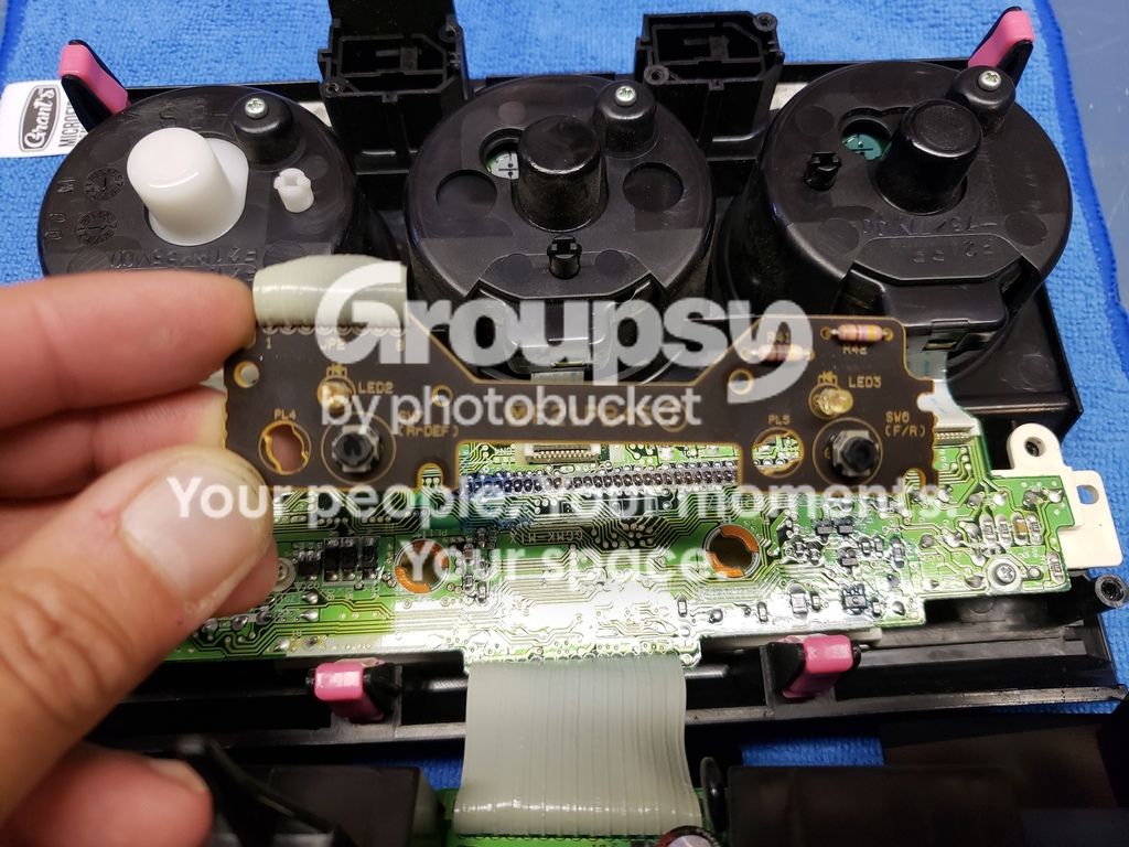
Now that you’re warmed up on soldering, we’re gonna pull apart the switches and replace those LEDs. This part is tricky only because the pads (copper runs with holes for the LEDs) tend to lift if they get even a little too much heat.
REMEMBER: Use only as much heat as you need, and apply it only as long as you need to.
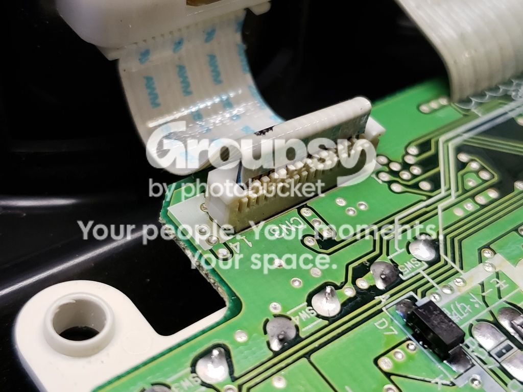
These switches come out surprisingly easily. Lift up on the ribbon cable holder catches. Be careful at this point, just use a screwdriver blade and sort of pull directly up. Do each side, then gently pull the ribbon cable free.
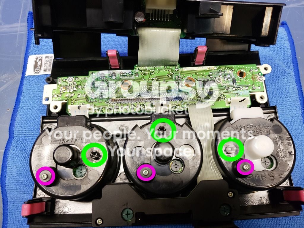
Then it’s just one screw each (in purple), and then you just have to squeeze these little posts (circled in green), and out pops each switch.
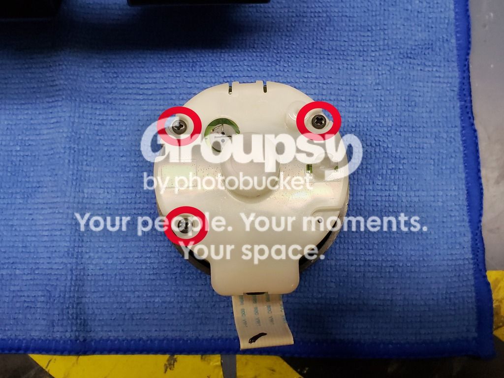
On the back of each switch there are three screws. Go ahead and remove these to get to the circuit board inside.
Once you’ve unclipped the circuit boards, you’ll see that the LEDs are clearly labeled on both sides. Just like with the recirc/defrost button LEDs, you’ll use solder wick and flux to remove and replace the existing LEDs. Pay attention to polarity!
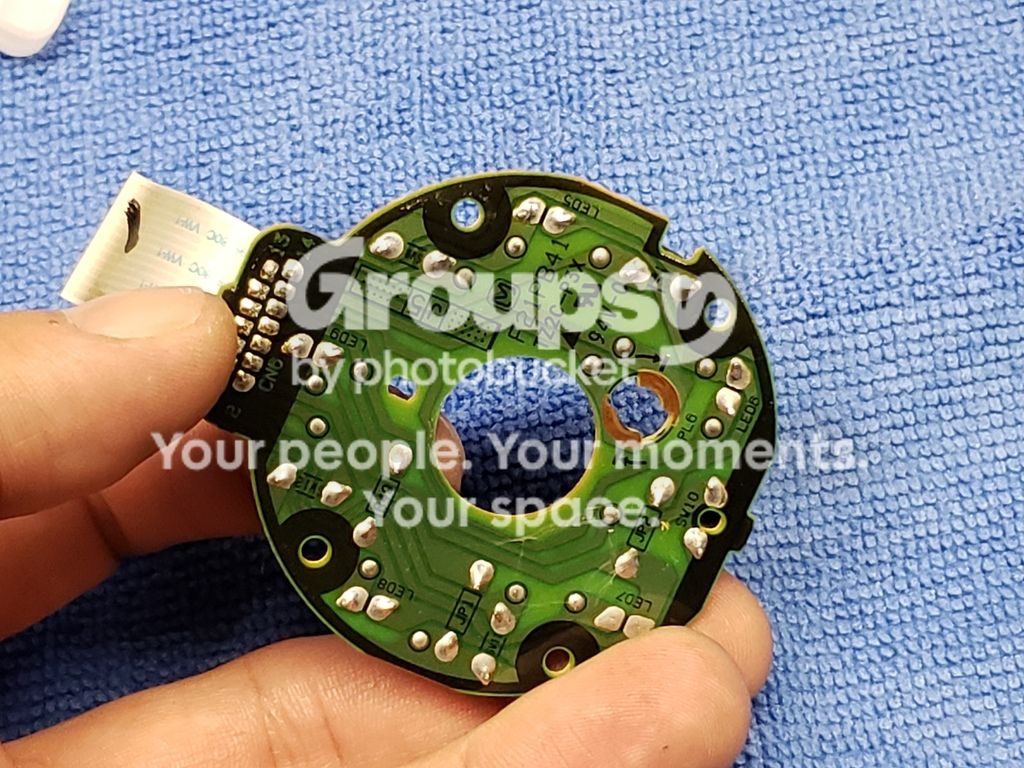
Now, do that again about a dozen times or so. These LEDs will be super bright when the parking lights/headlights are off, so fair warning, you may want to dab a little black paint on the top of the dome to lessen their brightness. They WILL dim when you turn lights on.
**THIS IS THE DO OR DIE PART**
This next step will ruin the switch, at least as far as OEM lighting. If you’re not comfortable with that, go ahead and reassemble everything.
Still here? Awesome.
Use your Dremel and a suitable bit (I use the cone grind stone bit) to widen the hole where the light bulb normally goes. It needs to be big enough for your RGB LED to pass through without getting hung up. Should look something like this when it’s correct:
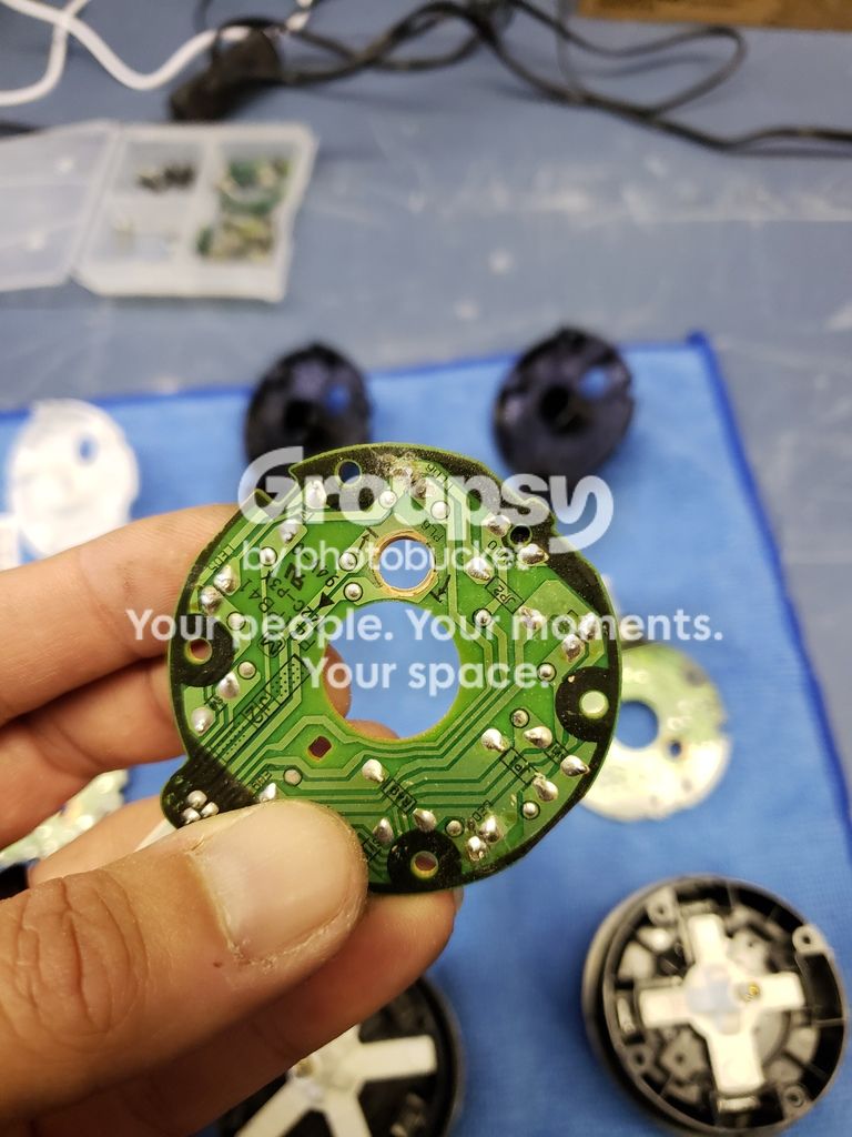
Now, do this for all three switches. Once that’s done, go ahead and replace the circuit board in the backing, but don’t reassemble the switch just yet. One more step.
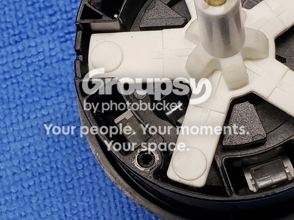
If you look into the other half of the switch, you’ll see where the light bulb normally goes, and how there’s a clear plastic ring inset. This allows the light from one bulb to light up all the different sections of the switch, but for our purposes we need to darken it a bit. So you’re going to take some paint on a small brush – I used my touch up paint, kind of like a fingernail polish brush – to drop some black paint in there. You’ll see what I mean when you look. You’re welcome to take this half apart – there’s a screw underneath the front cover, but it’s a real pain to get off without scratching it to hell – but you don’t need to. Just carefully lower the brush down until you get resistance.
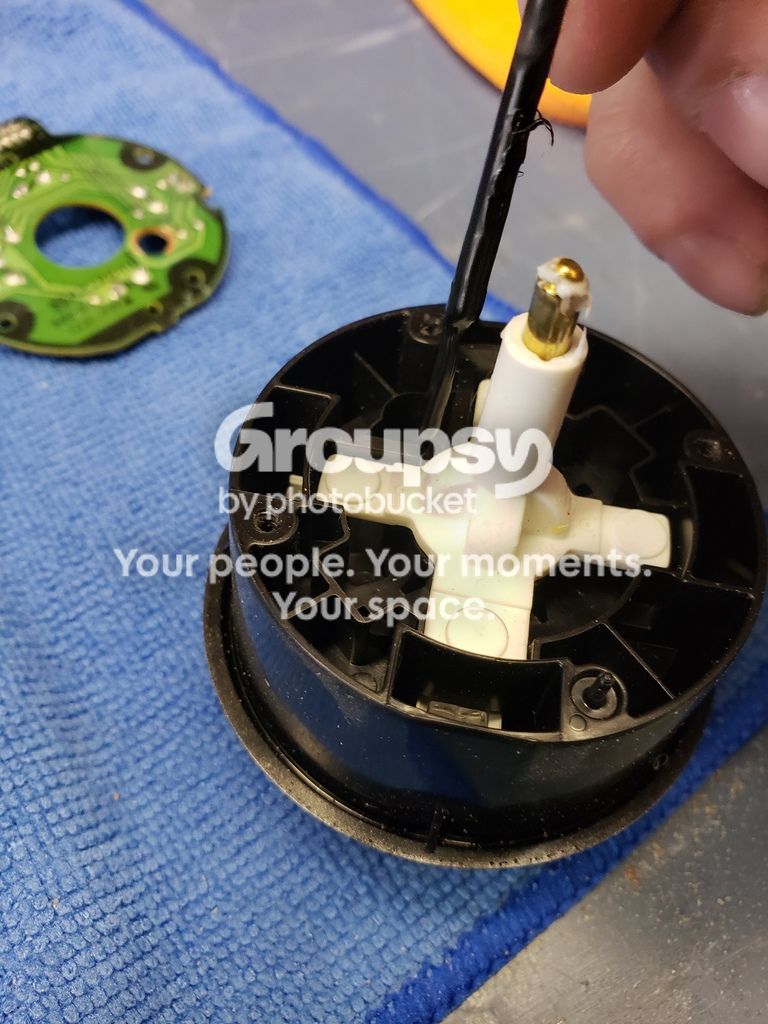
Let that dry and you can reassemble the switches, and even replace them in the panel.
First thing you should know: If you do this, you will not be able to put normal light bulbs back in, as this mod requires permanent modification to the boards of the switches.
Second: These lights are wired to be “on” when the parking lights or headlights are on. This means that the LCD and switches will NOT be lit with the exterior lights off, and that’s how I wanted it. To do any more than this would require a lot more time and engineering than I wanted to put into this project, but you are welcome to jump off from here if you want. I feel like having the backlighting on when it’s bright outside is pointless anyway, but ymmv.
Third: This is an afternoon project, but plan for extra time because it’s always a good idea, and your 4Runner will be out of commission while you’ve got the HVAC out. Don’t try to start the truck without the HVAC plugged in – since the airbag indicator is located in the HVAC assembly, there’s a possibility starting it while unplugged will trip the airbag light, which (to my knowledge) has to be reset at the dealership.
Disclaimer: This writeup is intended as a guideline for modifying interior lights so that they are RGB LED driven. I am not claiming anything more than that this is the process I used, shortened for brevity, and that results may vary. Don’t blame me if you burn yourself, get flux in your eyes, etc., and don’t blame me if it doesn’t turn out exactly right the first time.
Things you’ll need:
Soldering iron / solder / flux and solder wick strongly recommended / heat shrink (especially small)
Screwdrivers / Dremel / black paint / cloth or electrical tape recommended
You’re going to need to order a few parts online.
First, you’ll need an RGB controller of some sort. Whether it’s IR remote controlled or via Bluetooth/WiFi, it needs to be 12v driven. I’ve used both of these and they work well.
https://www.amazon.com/gp/product/B01JS0KEBW/ - Wifi/App controlled
https://www.amazon.com/gp/product/B00AF5YOK2/ - IR remote, no app.
Second, you’ll need some LEDs and wire.
https://www.amazon.com/gp/product/B07FDW4M89/ - You won’t use 100 feet, but it’s nice to have on hand.
https://www.amazon.com/gp/product/B0777BQC1P/ - These aren’t strictly necessary, but nice to have handy as well.
https://www.amazon.com/gp/product/B01AUI4VR4/ - These are the LEDs I used to replace the orange triangle lights in the switches. I used white, but you could theoretically use any color you can want, as long as it’s 3mm. These are 3V and work just fine.
https://www.amazon.com/gp/product/B01C19ENFK/ - These are the RGB LEDs used to light up the rest. Note that they’re common anode, that’ll be important when we wire em up.
https://www.amazon.com/gp/product/B06Y5GC3VY/ - These are the resistors that regulate the voltage to the LEDs. I bought a big variety pack, but really you only need the 100 ohm, 150 ohm, and 180 ohm resistors, at 1W power. If you buy a variety pack you can experiment, but make sure they’re at least 1W rated.
https://www.amazon.com/UTP-Circuit-Adapter-Circuit-Accessories/dp/B07FKWRV48/ - Always handy to have fuse taps around.
https://www.amazon.com/gp/product/B079RBL339/ - when you’re DIYing 12V projects, these are always a good thing to have on hand.
Step-By-Step
Start off by pulling the HVAC panel out. It’s super simple – remove the cubbie thing by opening and then pulling up on it, remove the 10mm bolt from the bottom of the HVAC panel, and pull it out.

Now you have the HVAC panel free, unplug the one plug in the back and take it to your work area.
We’re gonna pull the lights first off. Just take a flathead screwdriver and give them a counterclockwise twist, they’ll come right out.

Next we’ll remove some screws. The top part will flip up, and the cover on the bottom cover piece will lift right off.

Now we’ve got that stuff open, time for a little test solder. Unscrew these two screws:

Flip it over and you’ll see the LEDs. Go ahead and heat up your soldering iron, use your solder wick and flux, then go ahead and swap out those LEDs for a pair from what you bought online. Pay attention to the polarity of the LEDs. Look close at the LEDs before you replace them, make sure the new ones are oriented the same.

Now that you’re warmed up on soldering, we’re gonna pull apart the switches and replace those LEDs. This part is tricky only because the pads (copper runs with holes for the LEDs) tend to lift if they get even a little too much heat.
REMEMBER: Use only as much heat as you need, and apply it only as long as you need to.
These switches come out surprisingly easily. Lift up on the ribbon cable holder catches. Be careful at this point, just use a screwdriver blade and sort of pull directly up. Do each side, then gently pull the ribbon cable free.

Then it’s just one screw each (in purple), and then you just have to squeeze these little posts (circled in green), and out pops each switch.

On the back of each switch there are three screws. Go ahead and remove these to get to the circuit board inside.

Once you’ve unclipped the circuit boards, you’ll see that the LEDs are clearly labeled on both sides. Just like with the recirc/defrost button LEDs, you’ll use solder wick and flux to remove and replace the existing LEDs. Pay attention to polarity!

Now, do that again about a dozen times or so. These LEDs will be super bright when the parking lights/headlights are off, so fair warning, you may want to dab a little black paint on the top of the dome to lessen their brightness. They WILL dim when you turn lights on.
**THIS IS THE DO OR DIE PART**
This next step will ruin the switch, at least as far as OEM lighting. If you’re not comfortable with that, go ahead and reassemble everything.
Still here? Awesome.
Use your Dremel and a suitable bit (I use the cone grind stone bit) to widen the hole where the light bulb normally goes. It needs to be big enough for your RGB LED to pass through without getting hung up. Should look something like this when it’s correct:

Now, do this for all three switches. Once that’s done, go ahead and replace the circuit board in the backing, but don’t reassemble the switch just yet. One more step.

If you look into the other half of the switch, you’ll see where the light bulb normally goes, and how there’s a clear plastic ring inset. This allows the light from one bulb to light up all the different sections of the switch, but for our purposes we need to darken it a bit. So you’re going to take some paint on a small brush – I used my touch up paint, kind of like a fingernail polish brush – to drop some black paint in there. You’ll see what I mean when you look. You’re welcome to take this half apart – there’s a screw underneath the front cover, but it’s a real pain to get off without scratching it to hell – but you don’t need to. Just carefully lower the brush down until you get resistance.

Let that dry and you can reassemble the switches, and even replace them in the panel.


