How to: Wiring Aux Reverse Lights

TKinstler

New member
I know this subject has been beaten to death, but for some reason I am still struggling with it. Appreciate any help, just want to do it right the first time.

I just purchased two Bean LED Industries, 16w, LED, 6" Flood Lights and his double wire harness. (Thanks macoyle) I want to hook these up so they light up when in reverse and also to a switch that I can turn them on whenever for exterior lighting. How exactly should I wire this and what do I need? Thanks!
 
Register to hide this ad
a DPDT switch, one side labeled "auto" and the other side labeled "on", when the switch is in the "neutral" position they are off. pull a wire from the hot side of the reverse circuit from under the dash for the auto side of the switch and a constant hot for the on side. Then you will need a diode when you bring the two hot wires into the lights, to keep from back feeding the hot leg of the other side of the switch. I will post a sketch in a bit.
 
I used a wireless system so I didn't have to run any new wires and switches. I did all my connections under the vehicle connecting it to the trailer hitch harness and added a relay so I could have them come on when in reverse, or anytime with the remote. I left them tied into the Aux power of the harness as I wanted them to automatically turn off when the key was removed as I did not want to accidentally leave them on.

 
SAR_RUNNER, I believe what you are describing is exactly what I am looking for and need to do. If you could get me a simplified diagram that would be a huge help. Also best place to get these items?

Morphious, I appreciate the information and that definitely seems like a simpler hookup, but I have enough remotes on my key ring already and would most likely loose it if kept it inside somewhere.
 
Morphious, I appreciate the information and that definitely seems like a simpler hookup, but I have enough remotes on my key ring already and would most likely loose it if kept it inside somewhere.

No worries, I keep my remote in the overhead sun glass storage as that is where I keep my garage door opener too. Good luck on your install.
 
a DPDT switch, one side labeled "auto" and the other side labeled "on", when the switch is in the "neutral" position they are off. pull a wire from the hot side of the reverse circuit from under the dash for the auto side of the switch and a constant hot for the on side. Then you will need a diode when you bring the two hot wires into the lights, to keep from back feeding the hot leg of the other side of the switch. I will post a sketch in a bit.

Actually, there should be a relay(s) in between the switch and lights. It is good practice to keep the switch inside the vehicle isolated from the powered device. Also, with relays, you don't have to worry about power back feeding as only one contact will be closed at any given time...if wired up properly.

A little of the topic...but here is a good site to learn about relays (12Vdc)...and some creative ways to use them (logic circuits)...

http://www.the12volt.com/relays/relays.asp
 
Last edited:
Shouldnt need a relay if running LEDs, low enough amp draw. If it was a couple of KC Daylighters running 165W bulbs... I run LED Bars all the time off of a good quality 20-25A switch.
 
I know this subject has been beaten to death, but for some reason I am still struggling with it. Appreciate any help, just want to do it right the first time.

I just purchased two Bean LED Industries, 16w, LED, 6" Flood Lights and his double wire harness. (Thanks macoyle) I want to hook these up so they light up when in reverse and also to a switch that I can turn them on whenever for exterior lighting. How exactly should I wire this and what do I need? Thanks!

easy...look here
http://www.toyota-4runner.org/4th-g...5s-03-sport-4-7l-v8-build-14.html#post1504119
 
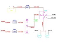
So last night I put this together. Its kind of a mix of what everyone has said and from all the articles I have read on it. Does everyone feel this would work correctly and be safe? [MENTION=95673]SAR_Runner[/MENTION], [MENTION=3958]jwyshrek[/MENTION], [MENTION=93434]gshadow325[/MENTION]
 

Attachments

  • LIGHTS (2).jpg
    LIGHTS (2).jpg
    26.2 KB · Views: 1,362
questions?

-what is the sp/dt?
-10amp fuse might be too small depending on the load on the lights.
-16ga wire is going to be too small
-12ga is going to be too big
-where are you doing your connections?
-if you doing this in the rear, might as well run a larger gauge wire like 8 or 4 so in the future you have it ran already.
-if you doing it in the back then wiring will be a little different and you should run another wire too. but this is only after you answer the other questions.

here is a picture of my corrections
 
Shouldnt need a relay if running LEDs, low enough amp draw. If it was a couple of KC Daylighters running 165W bulbs... I run LED Bars all the time off of a good quality 20-25A switch.

personally, and professionally. I do not like running current thru switches. using switches as ground switches, where no load goes thru them. why? switches always say they rated at blah blah blah. well you know what? they always melt soon or later. they rated to, lets say "X" switch @ 10amps, but 10amps for how long? 5 minutes, 10,20 1 hour? there lies your problem. time, time with that load creates heat, heat on plastic=melting. over time that melting turns into a burned switch/problems.
 
personally, and professionally. I do not like running current thru switches. using switches as ground switches, where no load goes thru them. why? switches always say they rated at blah blah blah. well you know what? they always melt soon or later. they rated to, lets say "X" switch @ 10amps, but 10amps for how long? 5 minutes, 10,20 1 hour? there lies your problem. time, time with that load creates heat, heat on plastic=melting. over time that melting turns into a burned switch/problems.

I think you mentioned this in another thread, but i'm confused. Isn't it just 20A or whatever of ground current instead of + current running through it and is thus equally likely to melt the switch? :confused: I could see the advantages of switching ground to clean up the wiring, shorter runs, etc. but I thought the current was the same?
 
I think you mentioned this in another thread, but i'm confused. Isn't it just 20A or whatever of ground current instead of + current running through it and is thus equally likely to melt the switch? :confused: I could see the advantages of switching ground to clean up the wiring, shorter runs, etc. but I thought the current was the same?

no the ground is to only latch a relay.
 
SPDT = Single Pole Double Throw Switch. I figured I needed this to be able to turn the lights on if I am just sitting in park or whatever? Then put it back to the "REV" side to allow them to come one whenever in reverse.
You right about the wire size I had those reversed by accident. Should of been 12 off the battery and 16 to the switch. My bad.
My thought is I would do as much as possible under the dash then just do the long run of wire to the lights. So I could tap the reverse line by the fuse box and then grab a ACC at the fuse box.
I looked at your write up on momos build. Arent you still running current threw that switch as well?
I am open to any layout for this, just want it to be safe and correct. So if you feel I should do it a different way I am listening. Like I said I am a rookie at this wiring misc.. My lights are only 16 watts so figured the amperage to be real low.
 
no the ground is to only latch a relay.

But if you use a + current to trigger the relay and a + output for the relay isn't it the same thing? I just don't understand why the amount of current is different whether or not it's ground or +? I think [MENTION=50591]gaterose[/MENTION] and I talked about this once?
 
First thing I see is the fact that you are using 16ga from the battery to the relay and should be using 12ga. the 12 ga that you are using on the switch can be down sized if you are running to a relay. if it is a 20A load you should be 12 ga or thicker, anything running through a 5A fuse can be pretty small.

Not the best page, but I have used it in the past as a resource for sizing wire commercially and to find the cross-sectional area.
American Wire Gauge (AWG) Cable Conductor Size Chart / Table

you will need a DPDT (Double Pole Double Throw) to have two different power sources coming in and then going out. otherwise it is the reverse of your drawing. one power source and two outputs. Here is the Diagram from OTRATTW, Jim is a great resource if you have questions or need to know the right switch to buy.
http://www.otrattw.com/wiring/JD66B.pdf
 
To the OP...your drawing conceptually looks okay, but you do need some fine tuning and slight changes as mentioned by others on this thread.
 
But if you use a + current to trigger the relay and a + output for the relay isn't it the same thing? I just don't understand why the amount of current is different whether or not it's ground or +? I think [MENTION=50591]gaterose[/MENTION] and I talked about this once?

same thing. yes. electricity likes path of least resistance. there is a physical latch that happens when you turn on a switch. it litterally arcs inside the switch. thus making a burn mark on the brass inside the switch. eventually the resistance is high enough it starts to create heat. with heat come melting plastic. then eventual failure. this does not happen with using it as a ground switch. plus side to this is if ever the wire gets pinched it will only turn on the relay. with a positive, it will burn and burn and burn till something melts, fuse wire ect.

you dont need the spdt, just two diodes 3 amps is fine
 
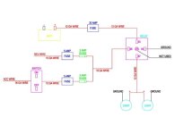
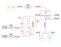
Ok, so if I am following everyone correctly I can do it two ways? Are these now correct and if so which one is the better of the two? See revised sketches below.
 

Attachments

  • LIGHTS1 (2).jpg
    LIGHTS1 (2).jpg
    22.5 KB · Views: 1,683
  • LIGHTS2 (2).jpg
    LIGHTS2 (2).jpg
    28.3 KB · Views: 2,893
The second one looks good...but you don't need that diode with that particular type of switch since you'll only have one 'hot' going to the relay at a time.
 

Members online

Forum statistics

Threads
278,309
Messages
3,554,075
Members
248,016
Latest member
Advally Service

Trending content

Back
Top