
You are using an out of date browser. It may not display this or other websites correctly.
You should upgrade or use an alternative browser.
You should upgrade or use an alternative browser.
I found "The One", 2001 Sport Ed. TRD SC'd
- Thread starter BigFishAllDay
- Start date


BigFishAllDay
New member
Those limit straps look so cool!
Always good to see the less than common mods being done, and you are the king of those!
I'm itching to hear how that valve body works for you, sure looks like its ready for some power! I think you found the only salvageable part on that 4runner at the yard haha.
Thanks, Jim! I've always thought that limit straps looked pretty cool as well. In this case they were definitely needed, and the looking cool was a bonus, so it worked out well. I'm hoping to get the VB installed either this week or next. I'll definitely post a review once I've got some time on the pedals.
Did you go check out that 2002? Man that thing was toasted, wasn't it? Fire is by far the worst thing that can happen to a vehicle, IMO.
thanks for the write-up on the limit straps
how did you know where to locate the brackets on the frame before you welded them; did Steve include detailed instructions? do you also have a complete parts list for any extra hardware you had to purchase?
There are instructions as to where they should be located in the SS kit. Basically you want to mock up the entire setup, then place the bracket on the frame and locate the angle at which the bracket is in line with the strap from top to bottom, and across the frame. Then you just center it between the coil bucket and the bracket for the ABS sensor wires.
As far as the list of items needed, refer to Dirtco's post in the "front end noise" thread. I'm running the exact same setup that he's got.
Dirtco's Limit Strap List
Dang the luck on no snow! I can't even drive to my shop to play with the rig, due to snow!! Great work, makes me want to pick up the welding rods this Summer, but my welds are piss poor to say the least!!
Excellent work on the project, they look great!!!
Thanks, man! We finally got some snow down here, so the skiing has been great, but there are not alot of options for snow wheeling up in the mountains. I did some research on that road, and found several snow wheeling trip reports, so I figured it would be open. I guess maybe the U.S.F.S. is short staffed with the Fed budget cuts or something. I figured they closed it because they don't have the manpower to patrol it and/or go up there to recover people who go unprepared.
You'll love the VB upgrade. Although the install sucks!
Good to hear, Dous. You're one of the only other guys on the forum running one of these things, IIRC. I'm planning to lay some plastic sheeting down on the garage floor rather than trying to catch the fluid in a pan. When I pulled this VB it was a mess. I've watched IPT's install video a dozen times, and between that and the experience I got in removing this VB, I think it will go pretty smoothly.
Damn nice runner man... well done
Thanks for the compliments, Skidmarcx.

LittleCaesar
New member
Good luck with the VB install. I have done two (not on an A340) and they went well, but make sure you have zero distractions when you put it in. Zero.
I have to ask if your solenoids are marked Denso or Aisin. Just for a parts query plus I think my 1st/2nd gear solenoid may be on its last leg (no code though, and have not ohmed it out).
Once one gets to welding, I began asking myself why I did not get one earlier. Nice job with the straps.
The baby is growing. You must be giving her an extra jar of Gerbers each day.
I have to ask if your solenoids are marked Denso or Aisin. Just for a parts query plus I think my 1st/2nd gear solenoid may be on its last leg (no code though, and have not ohmed it out).
Once one gets to welding, I began asking myself why I did not get one earlier. Nice job with the straps.
The baby is growing. You must be giving her an extra jar of Gerbers each day.

Dous
New member
Good luck with the VB install. I have done two (not on an A340) and they went well, but make sure you have zero distractions when you put it in. Zero.
I have to ask if your solenoids are marked Denso or Aisin. Just for a parts query plus I think my 1st/2nd gear solenoid may be on its last leg (no code though, and have not ohmed it out).
Once one gets to welding, I began asking myself why I did not get one earlier. Nice job with the straps.
The baby is growing. You must be giving her an extra jar of Gerbers each day.
I think the worst part was the transmission fluid dripping onto my face while I was trying to install! I let the freaking transmission drip for hours before I even began working too
LittleCaesar
New member
Dous brings up a good point.
I used one of these, in fact I use one all the time when working under an auto while on my back and fluid is present. Get the ratcheting one in order to have the shield tilted at an angle without it moving so you can breath and not fog the darn thing up:
Amazon.com: 3M Professional Faceshield: Home Improvement
I used one of these, in fact I use one all the time when working under an auto while on my back and fluid is present. Get the ratcheting one in order to have the shield tilted at an angle without it moving so you can breath and not fog the darn thing up:
Amazon.com: 3M Professional Faceshield: Home Improvement
BigFishAllDay
New member
Good luck with the VB install. I have done two (not on an A340) and they went well, but make sure you have zero distractions when you put it in. Zero.
I have to ask if your solenoids are marked Denso or Aisin. Just for a parts query plus I think my 1st/2nd gear solenoid may be on its last leg (no code though, and have not ohmed it out).
Once one gets to welding, I began asking myself why I did not get one earlier. Nice job with the straps.
The baby is growing. You must be giving her an extra jar of Gerbers each day.
I agree with you on the zero distractions, and I made that clear to my Wife. I'll be taking pictures as much as I can, and taking it slow to make sure I don't miss anything. I don't want to have to drop the transmission pan more than once. RE the solenoids, there is a total of 4 on the VB, and 3 of them are stamped AISIN. The other one is unmarked. I took macro pictures of the entire VB from every possible angle, just for future reference. If you're curious, I can set you up to view the pictures... there are close to 100 of them.
I'm very happy to own a welder, and like you said, I wish I had bought one years ago. I'd probably have made my own F/R bumpers had I bought one at the first inkling.
Our little girl is getting very big. She's already over 14lbs (born at 7). She's still breastfeeding, so all that growth is thanks to Mama's good stuff.
I think the worst part was the transmission fluid dripping onto my face while I was trying to install! I let the freaking transmission drip for hours before I even began working too
I bet. I had it all in my hair, on my neck, face, shirt, etc. after the removal. My hands and forearms were soaked with trans fluid, but I dropped the pan and pretty much attacked it, so it was still draining while I was pulling it.
Dous brings up a good point.
I used one of these, in fact I use one all the time when working under an auto while on my back and fluid is present. Get the ratcheting one in order to have the shield tilted at an angle without it moving so you can breath and not fog the darn thing up:
Amazon.com: 3M Professional Faceshield: Home Improvement
Actually I already own one of those. I use it as a secondary layer of facial protection in front of my safety goggles whenever I'm using the angle grinder. I had a cutting wheel jump on me and go through my glove awhile back. After that I decided to up the amount of safety gear.
Good idea on using it for the VB install. I'll try that out.

4-Ripcord
New member
Thanks, Jim! I've always thought that limit straps looked pretty cool as well. In this case they were definitely needed, and the looking cool was a bonus, so it worked out well. I'm hoping to get the VB installed either this week or next. I'll definitely post a review once I've got some time on the pedals.
Did you go check out that 2002? Man that thing was toasted, wasn't it? Fire is by far the worst thing that can happen to a vehicle, IMO.
Yeah I went with a friend because they told them they got a tacoma. You weren't kidding, that thing was toasted.
LittleCaesar
New member
BFAD,
Thanks for confirming that the 4wd's solenoids are Aisin. No need for access to the pic gallery. I think the 340Es uses ones made by Denso. I have a couple of things I want to do before I drop the pan on mine again for a possible solenoid replacement.
I thought there are only three solenoids total; I don't know about the 4th one. I will look forward to a pic of it. Maybe it is the mysterious electrical connector that prevents shifting from 2nd to 3rd until the ECT reaches 130F.
Thanks for confirming that the 4wd's solenoids are Aisin. No need for access to the pic gallery. I think the 340Es uses ones made by Denso. I have a couple of things I want to do before I drop the pan on mine again for a possible solenoid replacement.
I thought there are only three solenoids total; I don't know about the 4th one. I will look forward to a pic of it. Maybe it is the mysterious electrical connector that prevents shifting from 2nd to 3rd until the ECT reaches 130F.

DGO-SR5
New member
I have the same issue with shifting from 2nd to 3rd until the trans warms up a bit. I can however get it to shift if I hit 2500rpm in 2nd. It pains me a bit to run it that high when its cold but otherwise its 26mph until it warms up enough to shift. Is this something that happens from the factory? It's pretty annoying really especially when the speed limit is 35
LittleCaesar
New member
Just another tip to add BFAD: use a tiny dab of Vaseline or better yet assembly goo (such has a low disintegration/melting point) to keep the check balls in place on the VB.
My buddy is putting in a shift kit in a C4 at the moment and even with outlining the VB on cardboard and putting everything where it is supposed to go, he lost a check ball in his garage by not using any goo. It took him two days to find it.
My buddy is putting in a shift kit in a C4 at the moment and even with outlining the VB on cardboard and putting everything where it is supposed to go, he lost a check ball in his garage by not using any goo. It took him two days to find it.

smkd13
New member
After wheeling it a little bit that day, it became apparent to me that the front end was now too low due to the added weight of the ARB/Winch. I was going to have to do something about it because it was rubbing pretty badly on the pinch weld on both sides.
old post but just what i was looking for!!! and if I am ever down your way gotta go fishing with ya.
BigFishAllDay
New member
IPT Valve Body Upgrade… DONE!
NOTE: If you have no interest in Transmission Valve Bodies, feel free to just move along down the road.
From the very first day I bought this 4Runner, I’ve wanted to upgrade the valve body. The primary goal in doing so is to ensure that the transmission can reliably handle the extra power from the supercharger on a long term basis. I hope this upgrade will take the transmission “to the finish line”, but at the very least I know it will help the transmission last as long as possible. While reliability is the primary goal, there are fringe benefits… most notably the increase in acceleration.
Before diving into this write up, I would suggest you read this EXCELLENT article by John @ IPT, which fully explains the ideas behind upgrading the VB, and the modifications that IPT performs.
Toyota Modified Valve Body | Toyota Shift Kit | AW4 Shift Kit
Link to IPT’s web page for this service
Toyota A340 Series Modified Valve Body
The “kick in the pants” that set this plan in motion was a lucky find at the local U-Pull-It yard. They had a 2002 Sport Edition on their lot with severe fire damage. Luckily, the VB was housed safely in a bath of transmission fluid under the vehicle, where it suffered no damage. The really lucky part was that this vehicle contained the same type of VB as my ’01.
3rd Gen 4Runners with 4WD and automatic transmissions all use the A340F. 2WD models use the A340E. Throughout the 3rd gen production run, Toyota used THREE different VB configurations inside the A340F’s. I can only guess as to what the cutoffs were, so if anyone knows for sure feel free to correct my guesses below.
The early model years (1996-1998?) used a VB like the one below. Notice the overall length, which is shorter than the later versions, and the presence of the tubes (there should be two tubes, one has been removed in this photo) on the left hand side. The tubes are transmission fluid paths that were integrated into the actual VB on later versions. Also note the connection for the transmission kick-down cable @ bottom center. The other end of that cable connects to the throttle body and controls line pressure in the transmission @ various throttle positions. Last, notice that there are only three electronically controlled shift solenoids. Two along one edge and the third at the end near the tube.
Photo Courtesy of Texas_Ace on YT, click the username to view a profile.
The mid generation model years (1998-2000?) used a VB like the one below. Notice the increase in overall length, and that the VB now encompasses the fluid paths that were previously separate tubes. Also, notice that there is still a connection for the transmission kick-down cable to control transmission line pressure. Finally, there are still three electronically controlled shift solenoids, but their position on the VB has changed. All three solenoids are now aligned on one side of the VB.
Photo Courtesy of Texas_Ace on YT, click the username to view a profile.

Last but not least you have the late model VB (I know for sure this one is found on 2001-2002 model years). This version retains the overall shape and size of the previous version, but there are changes to the hydraulic controls. Where line pressure was controlled manually by a kick-down cable on prior versions, it is now controlled electronically by the ECU using a 4th solenoid, the SLT solenoid. This goes hand in hand with the drive-by-wire feature found on the 01-02 models. Take a peek under the hood of a ’01-’02 and you’ll notice that there is only one cable connected to the throttle body, which is a failsafe throttle cable. The transmission kick-down cable is eliminated on these model years. This version also gets a 5th solenoid, which is the Shift Control Solenoid, however it is not electronically controlled. The two new solenoids are visible at bottom center, where the cam and kick down cable were located on previous models.

I was waiting to do the upgrade until I could get my hands on a spare VB because I wanted to keep my stock VB (just in case), and I didn’t want to have the 4Runner down for 2+ weeks. Now that I’d found a compatible VB, it was finally time to do the upgrade. I pulled the VB from the parts truck, took it home, and gave it a close inspection. Everything looked like it was in good shape, so I boxed it up and sent it off to IPT. I only took one picture of it before it left my hands.

After a conversation with John (owner of IPT), I shipped the VB out on Friday 2/1. IPT received the VB on Friday the 8th, and had it re-worked and shipped back out before noon on Tuesday the 12th. I had it back in my hands on Monday 2/18. Considering that the VB arrived at IPT late on Friday, they basically did a one day turnaround, which I thought was impressive. If you plan on doing this upgrade and sending in your own VB, plan on the vehicle being down for 2 weeks unless you want to pay through the nose for expedited shipping.
The VB, as I received it from IPT… nice and clean and ready for action.
I edited this picture to include identifiers showing the layout of the accumulator pistons as they relate to the VB.

Just for reference, the diagram below shows the layout of the solenoids on the 01-02 VB’s. You can compare to the pictures above and see exactly which solenoids the diagram is referencing. The solenoid references should be the same for the earlier versions of the VB as well, minus the “SLT” solenoid. However, as I mentioned earlier, the solenoid locations are slightly different on earlier versions.

One of the notable upgrades to the valve body is the new springs that IPT includes for the accumulator pistons. These springs are longer and have a higher spring rate than the factory springs. This puts more pressure on the pistons, and affects the amount of fluid pressure that must build behind them to engage/disengage the clutches in the transmission. The operation of the transmission is controlled via the various combinations of actions between the accumulator pistons, the opening/closing of the solenoids, and the position of the gear selector/OD switch.
The B-0 accumulator piston (overdrive brake), with upgraded spring from IPT

The C-2 accumulator piston (direct clutch), the larger spring is upgraded by IPT, the small spring remains stock

The B-2 accumulator piston (3rd brake), with upgraded spring from IPT

The C-0 accumulator piston (overdrive direct clutch), which retains the stock springs

There are many other springs contained within the VB and the SLT Solenoid, and the Shift Control solenoid. I’m not sure whether or not IPT makes changes to any of those springs, and I didn’t feel like taking the upgraded VB apart so I could find out.
After doing some research, I found that Toyota used two suppliers for the solenoids on the 01-02 models, and the part numbers are interchangeable. When I checked Toyota part catalogs for the solenoids I found that under each part number they listed an option for either an Aisin part or a Denso part. The VB that I removed from the ’02 parts 4Runner had Aisin solenoids on it.
The “SL” solenoid

The “S1” and “S2” solenoids

Last but not least, IPT throws in a new pan gasket to use in place of RTV, and a small container of transmission assembly lube. This stuff has a low melting/disintegration point, and can be used to hold things in place while installing the VB. Once the vehicle is started and the transmission fluid begins to warm up, the assembly lube dissolves and blends with the transmission fluid.

IPT was kind enough to make a video of the installation process, found here:
IPT Toyota A340 Valvebody Installation Instructions - YouTube
The written instructions can be downloaded here, just click “Toyota 4x4 and RWD Valve Body Instructions”:
IPT | Installation Instructions | Transmissions | Valve Body | Torque Converter
After taking some time to familiarize myself with the process, I started by dropping the pan and filter. The pan and the magnets inside of it were cleaner than I’d hoped. There was a very fine dark gray paste on the magnets, but there were no metal shavings, either steel or brass, to indicate bearing/clutch/bushing wear and tear.

I had a look inside the transmission filter (more of a screen) and it was pretty clean, too. There were some very fine particles present on the screen, but no major debris or clogging of the screen.

The filter is retained by four bolts of three different lengths, so as I removed them, I made a template to remind me where they went at re-assembly time.

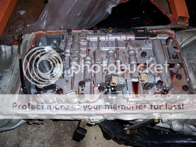
After the filter came down, I was staring at my stock VB.

If you ever attempt this job, I highly recommend making yourself a template of the bolt locations. As you remove the 20 bolts, of which there are 3 different lengths, simply stick them in the cardboard where they belong. When it comes time to re-assemble everything, you will know exactly where each bolt belongs.

NOTE: If you have no interest in Transmission Valve Bodies, feel free to just move along down the road.
From the very first day I bought this 4Runner, I’ve wanted to upgrade the valve body. The primary goal in doing so is to ensure that the transmission can reliably handle the extra power from the supercharger on a long term basis. I hope this upgrade will take the transmission “to the finish line”, but at the very least I know it will help the transmission last as long as possible. While reliability is the primary goal, there are fringe benefits… most notably the increase in acceleration.
Before diving into this write up, I would suggest you read this EXCELLENT article by John @ IPT, which fully explains the ideas behind upgrading the VB, and the modifications that IPT performs.
Toyota Modified Valve Body | Toyota Shift Kit | AW4 Shift Kit
Link to IPT’s web page for this service
Toyota A340 Series Modified Valve Body
The “kick in the pants” that set this plan in motion was a lucky find at the local U-Pull-It yard. They had a 2002 Sport Edition on their lot with severe fire damage. Luckily, the VB was housed safely in a bath of transmission fluid under the vehicle, where it suffered no damage. The really lucky part was that this vehicle contained the same type of VB as my ’01.
3rd Gen 4Runners with 4WD and automatic transmissions all use the A340F. 2WD models use the A340E. Throughout the 3rd gen production run, Toyota used THREE different VB configurations inside the A340F’s. I can only guess as to what the cutoffs were, so if anyone knows for sure feel free to correct my guesses below.
The early model years (1996-1998?) used a VB like the one below. Notice the overall length, which is shorter than the later versions, and the presence of the tubes (there should be two tubes, one has been removed in this photo) on the left hand side. The tubes are transmission fluid paths that were integrated into the actual VB on later versions. Also note the connection for the transmission kick-down cable @ bottom center. The other end of that cable connects to the throttle body and controls line pressure in the transmission @ various throttle positions. Last, notice that there are only three electronically controlled shift solenoids. Two along one edge and the third at the end near the tube.
Photo Courtesy of Texas_Ace on YT, click the username to view a profile.
The mid generation model years (1998-2000?) used a VB like the one below. Notice the increase in overall length, and that the VB now encompasses the fluid paths that were previously separate tubes. Also, notice that there is still a connection for the transmission kick-down cable to control transmission line pressure. Finally, there are still three electronically controlled shift solenoids, but their position on the VB has changed. All three solenoids are now aligned on one side of the VB.
Photo Courtesy of Texas_Ace on YT, click the username to view a profile.
Last but not least you have the late model VB (I know for sure this one is found on 2001-2002 model years). This version retains the overall shape and size of the previous version, but there are changes to the hydraulic controls. Where line pressure was controlled manually by a kick-down cable on prior versions, it is now controlled electronically by the ECU using a 4th solenoid, the SLT solenoid. This goes hand in hand with the drive-by-wire feature found on the 01-02 models. Take a peek under the hood of a ’01-’02 and you’ll notice that there is only one cable connected to the throttle body, which is a failsafe throttle cable. The transmission kick-down cable is eliminated on these model years. This version also gets a 5th solenoid, which is the Shift Control Solenoid, however it is not electronically controlled. The two new solenoids are visible at bottom center, where the cam and kick down cable were located on previous models.
I was waiting to do the upgrade until I could get my hands on a spare VB because I wanted to keep my stock VB (just in case), and I didn’t want to have the 4Runner down for 2+ weeks. Now that I’d found a compatible VB, it was finally time to do the upgrade. I pulled the VB from the parts truck, took it home, and gave it a close inspection. Everything looked like it was in good shape, so I boxed it up and sent it off to IPT. I only took one picture of it before it left my hands.
After a conversation with John (owner of IPT), I shipped the VB out on Friday 2/1. IPT received the VB on Friday the 8th, and had it re-worked and shipped back out before noon on Tuesday the 12th. I had it back in my hands on Monday 2/18. Considering that the VB arrived at IPT late on Friday, they basically did a one day turnaround, which I thought was impressive. If you plan on doing this upgrade and sending in your own VB, plan on the vehicle being down for 2 weeks unless you want to pay through the nose for expedited shipping.
The VB, as I received it from IPT… nice and clean and ready for action.
I edited this picture to include identifiers showing the layout of the accumulator pistons as they relate to the VB.
Just for reference, the diagram below shows the layout of the solenoids on the 01-02 VB’s. You can compare to the pictures above and see exactly which solenoids the diagram is referencing. The solenoid references should be the same for the earlier versions of the VB as well, minus the “SLT” solenoid. However, as I mentioned earlier, the solenoid locations are slightly different on earlier versions.
One of the notable upgrades to the valve body is the new springs that IPT includes for the accumulator pistons. These springs are longer and have a higher spring rate than the factory springs. This puts more pressure on the pistons, and affects the amount of fluid pressure that must build behind them to engage/disengage the clutches in the transmission. The operation of the transmission is controlled via the various combinations of actions between the accumulator pistons, the opening/closing of the solenoids, and the position of the gear selector/OD switch.
The B-0 accumulator piston (overdrive brake), with upgraded spring from IPT
The C-2 accumulator piston (direct clutch), the larger spring is upgraded by IPT, the small spring remains stock
The B-2 accumulator piston (3rd brake), with upgraded spring from IPT
The C-0 accumulator piston (overdrive direct clutch), which retains the stock springs
There are many other springs contained within the VB and the SLT Solenoid, and the Shift Control solenoid. I’m not sure whether or not IPT makes changes to any of those springs, and I didn’t feel like taking the upgraded VB apart so I could find out.
After doing some research, I found that Toyota used two suppliers for the solenoids on the 01-02 models, and the part numbers are interchangeable. When I checked Toyota part catalogs for the solenoids I found that under each part number they listed an option for either an Aisin part or a Denso part. The VB that I removed from the ’02 parts 4Runner had Aisin solenoids on it.
The “SL” solenoid
The “S1” and “S2” solenoids
Last but not least, IPT throws in a new pan gasket to use in place of RTV, and a small container of transmission assembly lube. This stuff has a low melting/disintegration point, and can be used to hold things in place while installing the VB. Once the vehicle is started and the transmission fluid begins to warm up, the assembly lube dissolves and blends with the transmission fluid.
IPT was kind enough to make a video of the installation process, found here:
IPT Toyota A340 Valvebody Installation Instructions - YouTube
The written instructions can be downloaded here, just click “Toyota 4x4 and RWD Valve Body Instructions”:
IPT | Installation Instructions | Transmissions | Valve Body | Torque Converter
After taking some time to familiarize myself with the process, I started by dropping the pan and filter. The pan and the magnets inside of it were cleaner than I’d hoped. There was a very fine dark gray paste on the magnets, but there were no metal shavings, either steel or brass, to indicate bearing/clutch/bushing wear and tear.
I had a look inside the transmission filter (more of a screen) and it was pretty clean, too. There were some very fine particles present on the screen, but no major debris or clogging of the screen.
The filter is retained by four bolts of three different lengths, so as I removed them, I made a template to remind me where they went at re-assembly time.
After the filter came down, I was staring at my stock VB.
If you ever attempt this job, I highly recommend making yourself a template of the bolt locations. As you remove the 20 bolts, of which there are 3 different lengths, simply stick them in the cardboard where they belong. When it comes time to re-assemble everything, you will know exactly where each bolt belongs.
Last edited:
BigFishAllDay
New member
I carefully lowered the valve body, and stopped to take a good look at the insides of my A340F

VBs are sensitive components, and I wanted to make sure that my stock VB was not exposed to any dust/contamination once removed from the vehicle. To ensure that it was protected, I purchased a large Tupperware container, lined it with shop towels, and stored the stock VB and associated parts inside.

At that point, I had to stop for the day with the transmission wide open. To prevent contaminants from getting inside the transmission, I used some bungee cords and a trash bag to cover it up for the night.

The next day I decided to compare the stock VB and the 02 IPT upgraded VB side by side to ensure that they were 100% identical. I inspected every square inch of both VBs and the only differences that I could find between the two were
1. The 02 VB had stampings on it that read “T5” and “T3”, and the 01 VB had stampings in the same locations that read “T2”. I imagine this was simply a variance in the manufacturing process from year to year, and probably denotes a place of production or other manufacturing detail.
2. The 02 VB had Aisin shift solenoids, while the 01 VB had Denso solenoids. I wasn’t sure about the interchangeability of the Denso and Aisin solenoids, so I swapped the stock Denso shift solenoids from the 01 VB onto the IPT upgraded 02 VB. I kept the Aisin solenoids for spares, and now that I’ve confirmed that they are interchangeable, I can install them down the road if I ever have a solenoid failure. For now, they have been installed onto the stock 01 VB. I did NOT swap the SLT line pressure control solenoid. I suspect that IPT may have modified this solenoid to adjust the line pressure in the transmission, based on the fact that I observed what appeared to be a non-OEM spring loaded in the tip of the solenoid.
Here are a couple shots of the Denso solenoids for reference
The “SL” solenoid


You can barely see the “Denso” stamping on the SL solenoid in this pic

The “S1” and “S2” solenoids


The 02 IPT upgraded VB, with Denso solenoids swapped over, ready for install


While I had the solenoids out, I decided to remove the SLT line pressure control solenoid, just to have a look at it. This is the 4th solenoid that was added on the latest version of the A340F VB.


Next, it was time to clean up the mating surfaces of the transmission pan and the transmission itself. I used a razor blade to trim off the majority of the excess RTV. To get it nice and clean, I first tried scraping with a hard plastic scraper, but that was ineffective. I went to a razor blade, but it was not only dangerous to me, but the mating surfaces as well, and tended to try and gouge the metal. Finally I got a 3M abrasive pad, dipped it in old transmission fluid, and used it to scrub the remainder of the old RTV off the mating surfaces. It took about an hour to get the pan nice and clean.

The hardest part of the whole job is putting the upgraded VB, check valve, accumulator pistons, and springs back into the transmission. The assembly lube that IPT sends with the VB will be your best friend here. I used generous quantities to hold the springs & pistons in place then carefully raised the VB and bolted it up. Before attempting to put the VB into place make sure to put the shifter for the transmission in “Neutral” so that the “rooster comb” on the transmission shifting assembly will engage the detent spring, along with the manual valve on the VB (see the IPT install instructions for details).
Whew!!! It’s in!

I’d like to add a hint here regarding the requirement to put the transmission in Neutral before installing the VB. In order to place the shifter in Neutral, you have to turn the key in the ignition, which will power up the ECU. When the ECU powers up, it will see that none of the transmission solenoids are connected and will trip the Check Engine Light (CEL), with a trouble code for EACH solenoid. I nearly crapped my pants when I went to start the 4Runner after the install and pulled FOUR trouble codes on my Scan Gauge. I looked them up and saw that they were all solenoid related codes and freaked out a little bit before I realized what had happened.
To avoid getting a CEL, there are two things you can do:
1. Use the shift lock override button located just in front of, and to the right of, the transmission shifter to place the shifter in Neutral WITHOUT turning the key in the ignition.
2. Put a bucket or some other type of support under the vehicle, and rest the VB on it, then plug in all the solenoids before turning the key in the ignition. If you go this route, you’ll have to get back under the vehicle and put the VB up with the wiring attached.
Option 2 would be a pain in the rear, so if I were to do this job again, I’d go with option 1 to avoid tripping the CEL. By the way, after I cleared the trouble codes I had no more issues.
Before you go on, make sure that you have securely plugged in all of the solenoids. CHECK!

I purchased a new transmission filter/screen, but ultimately chose to re-use my old one since it was clean and the gaskets were in good condition. The Toyota part number for the filter is 35330-60030 (Strainer Assy, Oil), and cost me $46 at my local dealership.

As I mentioned earlier, IPT includes a transmission pan gasket which makes life much easier compared to installing the pan with a bead of RTV sealant. I’ve been driving the 4Runner for over a week now, and I’ve been checking for leaks from the pan gasket every day… so far, so good.
BOOM!

When it came time to choose a transmission fluid, I couldn’t bring myself to choke down $9-15/quart for synthetics, so I ordered a case of Toyota T-IV. When I went to pick up the Toyota fluid, I asked them to double check the compatibility of T-IV with my transmission. The main reason that I asked is because the 3rd Gen 4Runner Owner’s Manual specifies ONLY Dexron-II, Dexron-III or equivalent fluids. The guys at the dealer told me that they showed the same info, and suggested that I use Dex-III rather than the Toyota T-IV. I asked if they stocked Toyota Dex-III fluid, and they did not. When I asked them what they used when they did a transmission service on the older vehicles calling for Dex-III, they told me that they used NAPA Dex-III ATF. So, I went to go see NAPA.
12 Quarts @ $4.69/quart

Throughout the job, I collected all of the old transmission fluid in a 5-gallon bucket that I had previously marked with graduated lines indicating the fluid level in the bucket, in quarts. The total amount that I drained off the transmission was 8 quarts, so exactly 8 quarts of new fluid went back in. A nice side benefit of upgrading the VB is that you end up replacing the majority of your ATF with fresh fluid.
A long necked funnel with a narrow spout is extremely useful when it comes time to re-fill the transmission.

If anyone wants to see additional pictures of the VB, let me know. I took detailed macro shots of the entire (assembled) VB before installation.
Well friends, that’s about it for this novel. If you made it this far, thanks for reading and good luck if you decide to have this upgrade performed on your own VB.
VBs are sensitive components, and I wanted to make sure that my stock VB was not exposed to any dust/contamination once removed from the vehicle. To ensure that it was protected, I purchased a large Tupperware container, lined it with shop towels, and stored the stock VB and associated parts inside.
At that point, I had to stop for the day with the transmission wide open. To prevent contaminants from getting inside the transmission, I used some bungee cords and a trash bag to cover it up for the night.
The next day I decided to compare the stock VB and the 02 IPT upgraded VB side by side to ensure that they were 100% identical. I inspected every square inch of both VBs and the only differences that I could find between the two were
1. The 02 VB had stampings on it that read “T5” and “T3”, and the 01 VB had stampings in the same locations that read “T2”. I imagine this was simply a variance in the manufacturing process from year to year, and probably denotes a place of production or other manufacturing detail.
2. The 02 VB had Aisin shift solenoids, while the 01 VB had Denso solenoids. I wasn’t sure about the interchangeability of the Denso and Aisin solenoids, so I swapped the stock Denso shift solenoids from the 01 VB onto the IPT upgraded 02 VB. I kept the Aisin solenoids for spares, and now that I’ve confirmed that they are interchangeable, I can install them down the road if I ever have a solenoid failure. For now, they have been installed onto the stock 01 VB. I did NOT swap the SLT line pressure control solenoid. I suspect that IPT may have modified this solenoid to adjust the line pressure in the transmission, based on the fact that I observed what appeared to be a non-OEM spring loaded in the tip of the solenoid.
Here are a couple shots of the Denso solenoids for reference
The “SL” solenoid
You can barely see the “Denso” stamping on the SL solenoid in this pic
The “S1” and “S2” solenoids
The 02 IPT upgraded VB, with Denso solenoids swapped over, ready for install
While I had the solenoids out, I decided to remove the SLT line pressure control solenoid, just to have a look at it. This is the 4th solenoid that was added on the latest version of the A340F VB.
Next, it was time to clean up the mating surfaces of the transmission pan and the transmission itself. I used a razor blade to trim off the majority of the excess RTV. To get it nice and clean, I first tried scraping with a hard plastic scraper, but that was ineffective. I went to a razor blade, but it was not only dangerous to me, but the mating surfaces as well, and tended to try and gouge the metal. Finally I got a 3M abrasive pad, dipped it in old transmission fluid, and used it to scrub the remainder of the old RTV off the mating surfaces. It took about an hour to get the pan nice and clean.
The hardest part of the whole job is putting the upgraded VB, check valve, accumulator pistons, and springs back into the transmission. The assembly lube that IPT sends with the VB will be your best friend here. I used generous quantities to hold the springs & pistons in place then carefully raised the VB and bolted it up. Before attempting to put the VB into place make sure to put the shifter for the transmission in “Neutral” so that the “rooster comb” on the transmission shifting assembly will engage the detent spring, along with the manual valve on the VB (see the IPT install instructions for details).
Whew!!! It’s in!
I’d like to add a hint here regarding the requirement to put the transmission in Neutral before installing the VB. In order to place the shifter in Neutral, you have to turn the key in the ignition, which will power up the ECU. When the ECU powers up, it will see that none of the transmission solenoids are connected and will trip the Check Engine Light (CEL), with a trouble code for EACH solenoid. I nearly crapped my pants when I went to start the 4Runner after the install and pulled FOUR trouble codes on my Scan Gauge. I looked them up and saw that they were all solenoid related codes and freaked out a little bit before I realized what had happened.
To avoid getting a CEL, there are two things you can do:
1. Use the shift lock override button located just in front of, and to the right of, the transmission shifter to place the shifter in Neutral WITHOUT turning the key in the ignition.
2. Put a bucket or some other type of support under the vehicle, and rest the VB on it, then plug in all the solenoids before turning the key in the ignition. If you go this route, you’ll have to get back under the vehicle and put the VB up with the wiring attached.
Option 2 would be a pain in the rear, so if I were to do this job again, I’d go with option 1 to avoid tripping the CEL. By the way, after I cleared the trouble codes I had no more issues.
Before you go on, make sure that you have securely plugged in all of the solenoids. CHECK!
I purchased a new transmission filter/screen, but ultimately chose to re-use my old one since it was clean and the gaskets were in good condition. The Toyota part number for the filter is 35330-60030 (Strainer Assy, Oil), and cost me $46 at my local dealership.
As I mentioned earlier, IPT includes a transmission pan gasket which makes life much easier compared to installing the pan with a bead of RTV sealant. I’ve been driving the 4Runner for over a week now, and I’ve been checking for leaks from the pan gasket every day… so far, so good.
BOOM!
When it came time to choose a transmission fluid, I couldn’t bring myself to choke down $9-15/quart for synthetics, so I ordered a case of Toyota T-IV. When I went to pick up the Toyota fluid, I asked them to double check the compatibility of T-IV with my transmission. The main reason that I asked is because the 3rd Gen 4Runner Owner’s Manual specifies ONLY Dexron-II, Dexron-III or equivalent fluids. The guys at the dealer told me that they showed the same info, and suggested that I use Dex-III rather than the Toyota T-IV. I asked if they stocked Toyota Dex-III fluid, and they did not. When I asked them what they used when they did a transmission service on the older vehicles calling for Dex-III, they told me that they used NAPA Dex-III ATF. So, I went to go see NAPA.
12 Quarts @ $4.69/quart
Throughout the job, I collected all of the old transmission fluid in a 5-gallon bucket that I had previously marked with graduated lines indicating the fluid level in the bucket, in quarts. The total amount that I drained off the transmission was 8 quarts, so exactly 8 quarts of new fluid went back in. A nice side benefit of upgrading the VB is that you end up replacing the majority of your ATF with fresh fluid.
A long necked funnel with a narrow spout is extremely useful when it comes time to re-fill the transmission.
If anyone wants to see additional pictures of the VB, let me know. I took detailed macro shots of the entire (assembled) VB before installation.
Well friends, that’s about it for this novel. If you made it this far, thanks for reading and good luck if you decide to have this upgrade performed on your own VB.
Last edited:
BigFishAllDay
New member
-Summary & Initial Product Review-
Initial impressions are VERY GOOD. I immediately took the 4Runner for an easy drive to make sure that I hadn't missed a step or screwed something up, and to let the assembly lube disintegrate. To my great pleasure, everything worked as intended. Upshifts at light throttle were barely discernable from stock, engine braking remained unchanged, and the transmission otherwise felt great. I could already tell from the little kicks I was getting at low-mid throttle that the new VB was going to be fun.
I finished the install last Friday, and I've been driving the '01 everyday since. The main ECU is still in learning mode from a recent battery disconnection (limit strap install/welding), so the truck is still learning to be its normal self. However, that being said, I can already feel a marked increase in accelleration thanks to the rapid gear changes. At medium to full throttle, the gears change like a rifle bolt chambering a new round. Gear changes are fast, positive, and give you a little kick in your seat. I have also observed that the torque converter is locking up more quickly than it was before, especially on hills and freeway on-ramps. I haven't had a good opportunity to compare operating temperatures, since the weather around here has been in flux. I've been driving it pretty hard to test out the valve body, so that has it running warmer than normal as well. The best part is that I can now use the upper end of the RPM range in every gear, without worrying about my transmission. I've finally had the opportunity to drive this thing "like I stole it", and it has performed even better than I expected.
As far as my experience with IPT, I was totally satisfied. John was accessible and helpful whenever I called and was willing to put up with my barrage of questions. IPT honored their commitments for product turnaround and shipping times, and held up their end of the bargain 100%. They have a bunch of support media available to help customers with their installations, and their YouTube video alone makes the process almost idiot-proof. I highly recommend John and his team @ IPT Transmissions, and their Valve Body Upgrade service, for 3rd Gen 4Runner owners who are looking for better performance out of their A340 transmission.
If I could go back and choose again, would I still spend the $550 for this upgrade?
Hell. Freakin. Yes. It should have been one of the first things I did so I could have felt what this 4runner would do on stock size wheels/tires and without all the extra weight.
Long term review is pending... stay tuned.
:ranger:
-Reference Articles-
Great link for disassembly/reassembly instructions of the newest version of the A340F valve bodies
AutoTransTech: Getting a better look at the Toyota A340E Valve Body (Author: Mike Brown, Gears Magazine)
Good thread with general info on the A340
A340 Transmission issues and FAQs - Pirate4x4.Com : 4x4 and Off-Road Forum
Link to a write up from TTORA member SAR Squid79 about his IPT VB experience, and the ensuing discussion about shimming a VB versus doing the IPT upgrade, with input from John @ IPT
IPT Valve Body Upgrade - TTORA Forum
Initial impressions are VERY GOOD. I immediately took the 4Runner for an easy drive to make sure that I hadn't missed a step or screwed something up, and to let the assembly lube disintegrate. To my great pleasure, everything worked as intended. Upshifts at light throttle were barely discernable from stock, engine braking remained unchanged, and the transmission otherwise felt great. I could already tell from the little kicks I was getting at low-mid throttle that the new VB was going to be fun.
I finished the install last Friday, and I've been driving the '01 everyday since. The main ECU is still in learning mode from a recent battery disconnection (limit strap install/welding), so the truck is still learning to be its normal self. However, that being said, I can already feel a marked increase in accelleration thanks to the rapid gear changes. At medium to full throttle, the gears change like a rifle bolt chambering a new round. Gear changes are fast, positive, and give you a little kick in your seat. I have also observed that the torque converter is locking up more quickly than it was before, especially on hills and freeway on-ramps. I haven't had a good opportunity to compare operating temperatures, since the weather around here has been in flux. I've been driving it pretty hard to test out the valve body, so that has it running warmer than normal as well. The best part is that I can now use the upper end of the RPM range in every gear, without worrying about my transmission. I've finally had the opportunity to drive this thing "like I stole it", and it has performed even better than I expected.
As far as my experience with IPT, I was totally satisfied. John was accessible and helpful whenever I called and was willing to put up with my barrage of questions. IPT honored their commitments for product turnaround and shipping times, and held up their end of the bargain 100%. They have a bunch of support media available to help customers with their installations, and their YouTube video alone makes the process almost idiot-proof. I highly recommend John and his team @ IPT Transmissions, and their Valve Body Upgrade service, for 3rd Gen 4Runner owners who are looking for better performance out of their A340 transmission.
If I could go back and choose again, would I still spend the $550 for this upgrade?
Hell. Freakin. Yes. It should have been one of the first things I did so I could have felt what this 4runner would do on stock size wheels/tires and without all the extra weight.
Long term review is pending... stay tuned.
:ranger:
-Reference Articles-
Great link for disassembly/reassembly instructions of the newest version of the A340F valve bodies
AutoTransTech: Getting a better look at the Toyota A340E Valve Body (Author: Mike Brown, Gears Magazine)
Good thread with general info on the A340
A340 Transmission issues and FAQs - Pirate4x4.Com : 4x4 and Off-Road Forum
Link to a write up from TTORA member SAR Squid79 about his IPT VB experience, and the ensuing discussion about shimming a VB versus doing the IPT upgrade, with input from John @ IPT
IPT Valve Body Upgrade - TTORA Forum
Last edited:
BigFishAllDay
New member
Last, and least....
I got my hands on a new E-Locker ECU to replace the one I damaged so carelessly.

The damaged resistor on the old ECU was so burned up, I couldn't see the color coded stripes well enough to make a positive ID on the rating. I suspected it was a 680 ohm resistor, but now that I've seen this one, I'm thinking that it's more like a 6.8 ohm +/-5% rated resistor. The bands look like blue/grey/gold/gold to me. I'm glad I didn't stick a 680 ohm resistor on the old ECU's circuit board... 100X the resistance might have caused some issues.

I got my hands on a new E-Locker ECU to replace the one I damaged so carelessly.
The damaged resistor on the old ECU was so burned up, I couldn't see the color coded stripes well enough to make a positive ID on the rating. I suspected it was a 680 ohm resistor, but now that I've seen this one, I'm thinking that it's more like a 6.8 ohm +/-5% rated resistor. The bands look like blue/grey/gold/gold to me. I'm glad I didn't stick a 680 ohm resistor on the old ECU's circuit board... 100X the resistance might have caused some issues.
LittleCaesar
New member
Nice BFAD. I am curious if you will notice a change in ATF temps (higher or lower), the range in ATF temps while driving, etc. The valve body looks 10x easier to install than the ones I have played with from Chevy and Ford.
Gadget from URD loved his IPT transmission. I think that John had recommended in the past (via a YT thread maybe) the use of Lubegard black after his transmission rebuild. I don't know about the VB upgrade though.
Being on uncle duty at the moment, I am bookmarking this thread to read for the weekend.
Gadget from URD loved his IPT transmission. I think that John had recommended in the past (via a YT thread maybe) the use of Lubegard black after his transmission rebuild. I don't know about the VB upgrade though.
Being on uncle duty at the moment, I am bookmarking this thread to read for the weekend.

Similar threads

- Replies
- 2
- Views
- 3K

- Replies
- 0
- Views
- 294
- Replies
- 8
- Views
- 6K

- Replies
- 0
- Views
- 3K
- Replies
- 4
- Views
- 8K


