Johns06yota
Member
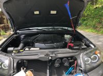
As some of you know I already have a "build" thread but to me I mostly did cosmetic things as apposed to an actual build. That is why I am starting this thread as I want to document and explain the entire process of me Turbo Charging my 4.0 4Runner. To my knowledge this will be the first one in existence and I intend to show you all how I'm going about this. Through my extensive research and gaining helpful knowledge from multiple people I have a general list of everything I am going to need. The plan is to utilize a t3/t4 turbo with a .63 A/R. On top of this to start I will be running no more than 5 PSI of boost to slowly see how the engine is going to handle this along with making sure the wideband readings are within a tolerable range. All of which will be in a rear mount setup. I will be running AN 4 braided line from the oil filter housing to the turbo feed with bolt on hose connections and AN 6 line from the turbo drain to a scavenge pump then back to the oil fill neck with multiple one way check valves in line. There are many other parts that are going into this but heres what I have done so far today.
Now to begin:
I today started with 2 components that in my mind are extremely important. Those components being a boost gauge and a wideband gauge. I did not want to cheap out of either of these so I went with AEM ones.
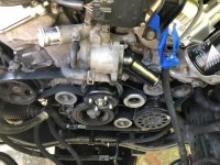
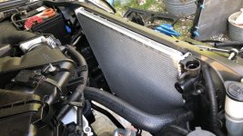
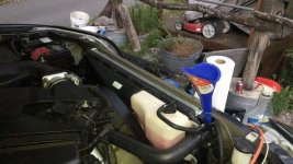
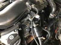
I started with finding a viable port after the throttle body to gain an accurate boost reading (for now only vacuum) I settled on a blocked off port and drilled the center out to be able to feed the line through. I then routed it down following factory vacuum lines and then terminating at the amp fuse holder I built.
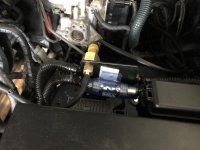
Here I drilled and bolted in place the electronic boost sensor and put on the vacuum line. Once I found this was secure I moved onto the next step of routing wires. For ease of access I decided to run the boost gauge wires and wideband wires at the same time.
To do this I cut a hole just big enough in the factory grommet and fed both sets of wires through. I left enough slack inside the vehicle and then zip tied the engine bay lines in place. I put the wideband wire to the side for now.
Next I went inside the vehicle and used an add a circuit to run these gauges when the vehicle is turned on. The positive wires were soldered and shrink wrapped and the negative was terminated on a body bolt.
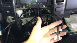
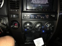
I next routed these cables up behind the center console trim for placement.
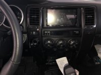
Lucky for me I found that the 4wd switch is the exact same size as the gauges so once these are finally installed, the boost gauge will be placed in that location, a second hole will be drilled on the other side for the wideband gauge and for now the plan is to mount the 4wd switch in the overhead console.
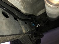
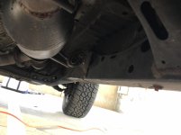
once this was tested I moved onto routing the wideband wires. For obvious reasons the cable is not long enough so I ended up extending it 6 feet. Is this overkill? Yes, but I wanted to have extra room incase I needed it. This was then routed around the frame and zip tied on place next to my muffler (future turbo location with wideband being placed after)
This is everything I was able to get done today. The rest of the parts need to be ordered but hope to do that within a few weeks.
Now to begin:
I today started with 2 components that in my mind are extremely important. Those components being a boost gauge and a wideband gauge. I did not want to cheap out of either of these so I went with AEM ones.
I started with finding a viable port after the throttle body to gain an accurate boost reading (for now only vacuum) I settled on a blocked off port and drilled the center out to be able to feed the line through. I then routed it down following factory vacuum lines and then terminating at the amp fuse holder I built.
Here I drilled and bolted in place the electronic boost sensor and put on the vacuum line. Once I found this was secure I moved onto the next step of routing wires. For ease of access I decided to run the boost gauge wires and wideband wires at the same time.
To do this I cut a hole just big enough in the factory grommet and fed both sets of wires through. I left enough slack inside the vehicle and then zip tied the engine bay lines in place. I put the wideband wire to the side for now.
Next I went inside the vehicle and used an add a circuit to run these gauges when the vehicle is turned on. The positive wires were soldered and shrink wrapped and the negative was terminated on a body bolt.
I next routed these cables up behind the center console trim for placement.
Lucky for me I found that the 4wd switch is the exact same size as the gauges so once these are finally installed, the boost gauge will be placed in that location, a second hole will be drilled on the other side for the wideband gauge and for now the plan is to mount the 4wd switch in the overhead console.
once this was tested I moved onto routing the wideband wires. For obvious reasons the cable is not long enough so I ended up extending it 6 feet. Is this overkill? Yes, but I wanted to have extra room incase I needed it. This was then routed around the frame and zip tied on place next to my muffler (future turbo location with wideband being placed after)
This is everything I was able to get done today. The rest of the parts need to be ordered but hope to do that within a few weeks.
Attachments
-
 IMG_1966 (1).jpg129.9 KB · Views: 3,207
 -
 IMG_1967 (1).jpg123.7 KB · Views: 3,081
 -
 IMG_1982.jpg129.5 KB · Views: 2,972
 -
 IMG_1965 (1).jpg127.4 KB · Views: 3,001
 -
 IMG_1970 (1).jpg133.6 KB · Views: 3,047
 -
 IMG_1972 (1).jpg125.7 KB · Views: 2,968
 -
 IMG_1973 (1).jpg128.6 KB · Views: 2,975
 -
 headlight.jpg124.7 KB · Views: 3,149