McCand's Build Thread

mccand

New member
########
Table of Contents:
########

I intend to keep this top post updated with the abbreviated history of why I did things, then detailed discussion for particular mods will be in their own post below.

As is usually best, let's start at the beginning, the backstory:

This all started when my sister backed my Subaru Outback into an I-beam in a parking garage. It wasn't totaled, and it ran fine, but it was never going to pass another safety inspection. A new (or new-used) car was needed, and I was moving to Hawaii shortly thereafter. A bit of research indicated that the 4Runner was going to be a good fit for what I needed, and a tiny bit more research indicated that it was a better choice for than most of the alternatives.

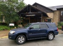
A lot of stalking the local car dealers finally found me my car: A 2006 blue 4Runner, with 114k miles, but in pretty good shape. The price was right, and a deal was struck.
IMG_20150708_094016.jpg

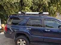
I promptly dubbed it "Bilbo", packed it with children, a German exchange student (long story), enough camping gear for a month or two, and took off for California. :lookout:

G1640825.jpg
(There are two children back there, I swear!)

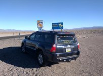
My only deadline was that I had to get to the Matson Shipping office in Oakland, CA in order to make sure it got on the boat. We had a couple of weeks to burn. Off we went!
IMG_20150716_181525.jpg

We made it, fortunately. It was a pretty epic trip - but that's a story for another post.

Once we got to Hawaii (and waited a couple weeks for the ship to bring Bilbo), we started doing all the Big Island fun things. As we became more comfortable, we realized that with a small amount of work, we could have a truckload more fun. I spent a while lurking on the forums, and started plotting what I was up against.

One of the driving reasons to get modding was 4X4 access to one of the really nice local beaches. The stock vehicle could do it, with care and periodic grinding noises from the giant chunks of lava rock that made the "road". I was pretty desperate to avoid needing a tow out of there ($$$$), and figured it was time to up my game.

The first step was writing a wishlist, then turning it into a plan.

The wishlist covers the high-level systems and everything I could think of that fell under that heading. I've listed the status for each entry so its obvious what parts are still wishful thinking.

  • Mechanical Upgrades
    • Suspension - Complete
    • Armor
    • Tires
  • Electrical
    • Second battery
    • Rear jump point
    • Better power access from rear compartment
  • Add-ons
    • Compressor with rear Air chuck - Functional, still needs some polish
    • Radio - Functional, still needs some polish
    • Winch
    • Charging Ports - Functional, still needs some polish
    • Bluetooth Integration - Functional, still needs some polish
    • Better Roof Rack
  • Accessories
    • Water Tank/Shower - Complete
    • Hi-lift - Complete
    • Shovel - Complete
    • Awning
    • Factory service manuals - Partially complete (Still need Vol 2 & 3)

I'm sure there's plenty of people here who have longer, better lists, but this one is mine.
 

Attachments

  • IMG_20150708_094016.jpg
    IMG_20150708_094016.jpg
    140.6 KB · Views: 1,960
  • G1640825.jpg
    G1640825.jpg
    130.3 KB · Views: 1,945
  • IMG_20150716_181525.jpg
    IMG_20150716_181525.jpg
    138.7 KB · Views: 1,890
Last edited:
Register to hide this ad
Air Compessor - Part 1

My first project was to put in an air compressor. My thinking was that this would be a relatively simple mod, and it would take care of one of my biggest worries - getting stuck with a flat tire. It has significant secondary benefits in that it can also be used to inflate the beach toys, get a camp fire going, or as I later realized, pressurize my water tank.

I ended up springing for the ARB CKMTA12. It's got a 100% duty cycle, is a reasonable form factor, I knew of at least three places I could fit it, and it has a pretty good reputation for reliability. Finally, I can order it from Amazon (Free shipping!)

It does have a disadvantage in that I could not find anywhere that sells a pre-fab bracket for 4th Gen T4Rs. Oh well. Now seems like a good time to mention that I used to live in Pittsburgh, where I had access to a Techshop that had all the tools that I'd have needed to make an awesome bracket. Now, I live on an island in the pacific, which has many positive aspects, but no Techshop. I have a hammer, saw, drill press and a vice, how hard can it be?

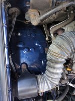
Since there was no preexisting bracket to dictate where this thing went, I got to pick my own spot. I decided to put it in the engine compartment, passenger side, just aft of the engine air intake.
IMG_20160814_093352.jpg
This spot has plenty of attachment points, and lots of space. the compressor could probably be mounted here in several ways:
  1. Flat
  2. Vertically along the side of the compartment
  3. Vertically along the rear firewall of the compartment.
Option 3 would probably be my preferred choice, but making a bracket for that was going to be relatively difficult given that it was going to be a tight fit. Option 1 was going to be pretty easy though, so that's what I went with.

Other locations that were considered and discarded were:
  • Next to the power steering fluid reservoir - Discarded because this is where I intend to put a second battery (someday...)
  • In the trunk - discarded because I like having extra trunk space, and the thing is pretty loud - plus it was going to be a pain to run the wiring that far.
  • Under the passenger seat. Discarded because I enjoy being married.

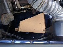
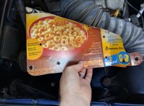
Now that I had a spot and orientation picked out, I broke out my two favorite sheet metal prototyping tools: Scissors and a box of Honey Nut Cheerios. After I'd eaten all the Cheerios, I started cutting up the box to fit what I had in mind.
IMG_20160814_093452.jpg

Figure out what holes I want to fasten to, add a couple of flanges for strength, test fit . . .
IMG_20160814_093448.jpg
. . . and we've got it.

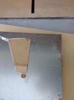
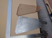
The next step is to turn the cardboard template into metal. First, copy over the pattern:
IMG_20160814_094808.jpg

Then some work with a saw:
IMG_20160814_102404.jpg

A fancy bending jig helps:
IMG_20160814_102836.jpg
When the jig won't do it, then I just put it in a vice and hammer on it until it looks right.

Finally:
IMG_20160818_183815.jpg

A couple passes with Rustoleum Undercoating paint and a compressor later:
IMG_20160819_092504.jpg

UPDATE: I've posted a scan of the cardboard template I used , should you want to try something similar. Keep in mind that after I had this all sketched out in metal, I added a couple of flanges, and once everything was built out, I trimmed a few spots to make sure there was no metal-to-metal contact with the body of the truck.

Click here to go to Part 2 of the compressor install.
 

Attachments

  • IMG_20160814_093352.jpg
    IMG_20160814_093352.jpg
    133.5 KB · Views: 1,902
  • IMG_20160814_093452.jpg
    IMG_20160814_093452.jpg
    132.8 KB · Views: 1,879
  • IMG_20160814_093448.jpg
    IMG_20160814_093448.jpg
    131.6 KB · Views: 1,877
  • IMG_20160814_094808.jpg
    IMG_20160814_094808.jpg
    139 KB · Views: 1,871
  • IMG_20160814_102404.jpg
    IMG_20160814_102404.jpg
    137.4 KB · Views: 1,862
  • IMG_20160814_102836.jpg
    IMG_20160814_102836.jpg
    132.9 KB · Views: 1,885
  • IMG_20160818_183815.jpg
    IMG_20160818_183815.jpg
    138.1 KB · Views: 1,919
  • IMG_20160819_092504.jpg
    IMG_20160819_092504.jpg
    135.5 KB · Views: 1,817
Last edited:
Suspension Upgrade

The great conjunction occurred, which many of you may be familiar with:

  1. I got a bit of a bonus from work
  2. A group buy for shocks opened up
  3. The good wife had a weak moment

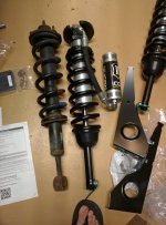
A couple of weeks later (shipping things to HI takes forever) I have a couple of Icon coilovers and UCAs sitting in my garage.
IMG_20160912_120609.jpg

  • Front coilovers (Icon 58745)
  • upper control arms (Icon 58451)

A week or two after that, my buddy Chris comes over and we start installing these suckers.

These were installed one Sunday afternoon/evening/late night while my wife was at work. As I recall, I started about 1 o'clock in the afternoon and finished at about 11 PM. Everything was done according to the included instructions, and occasionally, we referred to a youtube video that showed some of the little tricks that make life easier. We didn't permanently break anything (yay!), but it certainly took a while longer than I expected. I am reasonably certain that I fed the children and put them to bed at an appropriate time, but that's not really important, right?

Here are some "in process" pics:

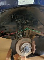
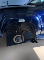
The old hardware, sans wheel. (The line on the tape is the distance to the ground before the upgrade)
IMG_20160924_145434.jpg

Getting the upper control arm in was pretty easy. The only tricky part was loosening (and later, tightening) the main bolt that holds it in place.
IMG_20160924_161155.jpg

Swapping the shocks was trickier.
IMG_20160924_175752.jpg
Getting at the bolts that secure the shock from above is tricky, the metal bathtub around the engine gets in the way. I ended up using some pliers to (gently) bend the offending flange just enough to allow the socket to access the bolt head. Also, connecting the lower control arm to the shock required some judicious use of force to get it into place. As everyone says, make sure you put the bottom bolt in the same way that it came out - if you turn it around it can tear the boot on the CV joint.
[I don't currently have a picture showing the new shocks with the wheel removed. I'll post one later - if I remember.]

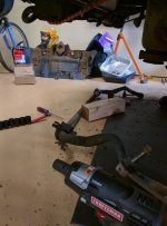
The thing that was the hardest from the perspective of two-handed people was getting the sway bar back in place. My free labor had left for the evening at that point, and it just took a lot of finagling to get all the bolts to line up.
IMG_20160924_172423.jpg

Also, once it's relocated, it rubs against the stock skid plate. Annoying, but pretty low on the list of things I want to take care of. If it starts making the wife mad, then maybe I'll get that new skidplate sooner . . .

All of the excitement came afterwards, though. The last step in the instructions for the shocks is to “get the vehicle professionally aligned”. A week or three later, I took the car to Firestone for exactly this purpose, and they called me back and said that the alignment bolts were all seized and this needed to be fixed by the dealer - and that it’s badly out of alignment. Things take time here, so I made a Friday appointment with the dealer to see what could be done.

The best case scenario was that the rust penetrant I soaked those things with worked, and that would be the end of the problems. Worst case, I spend a couple thousand dollars on getting the LCRs replaced, which would not make me happy. Did I mention that I just ordered the rear suspension upgrade parts the previous day? Nice timing!

Friday, the dealer got back to me: they managed to unstick two of the four alignment bolts. Unfortunately, it was one bolt on each LCA, and the other bolt doesn’t allow sufficient adjustment to fix the alignment, so I’m still stuck. They said the only thing to do was replace the entire LCA assembly, and they wanted $2K to do it. I said I’d think about it, and off we go. A friend of mine called around and one of his buddies who works on Toyotas exclusively said that it was possible to saw those suckers out then replace the bushings but it was hard, and might not be worth the effort compared to replacing the LCAs. I called around and one of the local shops offered to do the work for ~$900 - which sounds about 1100x better than the dealer. The guy there, Darren, says that they’ll reuse the ball joints, but replace the LCA, bushings, and cams. In case anybody asks, this is a great example of how a suspension upgrade gets more expensive fast!

A couple of days later, Darren called back and said that it was going to be more like $1,800, because parts are more expensive than he expected. (LCAs $400 each, bolt kit $300, rest is labor.) At least he told me before he had the thing in parts in his shop. The price was still better than from the dealer, so I went with it. It's probable that I could have got a better deal somewhere else, but I was out of energy to deal with it. :yield:

In the mean time, I put on the back shocks and springs:
  • Rear shocks (Icon 57810)
  • Rear springs (Icon 52700)
  • Shin guards (Icon 56100)

This was blissfully straightforward - follow the directions, and everything works well.

Anyhow, the car was then taken in to Darren, and wonder of wonders, he fixed it, in exchange for sufficient quantities of cash.

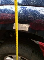
Interesting note: this was intended to be a 2 inch lift, but it ended up raising the front of the car 5 inches, and the rear 4 inches, which says something about how bad the existing suspension was. Hmmm.
IMG_20161012_173339.jpg

I've since taken the car down the Makalawena road (a nearby 4x4 trail to cool places), and the difference in performance was incredible. The extra inches of clearance eliminate essentially all scraping, and the ride is so much nicer. I submit to the record: the good wife said "This is way better, that shock upgrade was totally worth it!"
 

Attachments

  • IMG_20160912_120609.jpg
    IMG_20160912_120609.jpg
    128.3 KB · Views: 1,962
  • IMG_20160924_145434.jpg
    IMG_20160924_145434.jpg
    123.7 KB · Views: 1,865
  • IMG_20160924_161155.jpg
    IMG_20160924_161155.jpg
    130.8 KB · Views: 1,862
  • IMG_20160924_172423.jpg
    IMG_20160924_172423.jpg
    129.9 KB · Views: 1,848
  • IMG_20160924_175752.jpg
    IMG_20160924_175752.jpg
    133.6 KB · Views: 1,877
  • IMG_20161012_173339.jpg
    IMG_20161012_173339.jpg
    130.8 KB · Views: 1,836
Last edited:
I had the exact same problem. Put a lift on and went to align it to find out the lower bushing were ripped and bolts were seized. I would have just ordered all new LCAs because it comes with the bushings and replaces the ball joints and installed it myself but needed the rig back right away. The shop ended up cutting out the seized bolts and took a whole day getting the old bushings out but they did it at the original quote of about $900 luckily for me. But Moog bushings and bolts were used and now i think my left side has too much play. So I'll be replacing the bushings again with OEM. But yeah with all the research I did before hand I didn't hear about the LCA bushings and seized bolt problem being something I should have considered in my price of a lift. Now I see this problem everywhere.
 
Air Compressor - Part 2

Click here to go to Part 1 of the air compressor install.

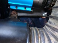
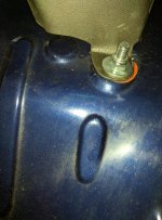
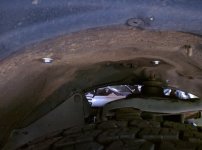
Anyhow, I now had a bracket and a compressor that attaches nicely to it. The next step was to bolt it into place. As I'd metioned earlier, one of the goals was to use existing features wherever possible and avoid drilling holes. Fortunately, there are lots of little bolt holes in this area.

Here's some pictures:

A plastic spacer and some rubber washers keep things level and rattle-free:
IMG_20160819_095333.jpg

The rubber washer on the other side:
IMG_20160819_095342.jpg

From underneath:
IMG_20160819_095410.jpg
One of these bolts used to have a weld-nut on it. While I was trying to clean out the rusty threads, the tack welds holding it in place broke off. Oh well. One more locknut goes in the shopping basket . . .

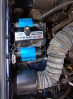
And voila! A compressor, mounted in my truck. Of course, it's not going to work until I get the wiring dealt with.
IMG_20160819_095324.jpg

Routing the wiring was pretty straight-forward. ARB supplies a pretty nice set of wire harnesses that are quite easy to handle. Using plenty of zip-ties, I ran everything along the front of the engine compartment, then back along the driver's side of the compartment to the huge gasket that everything passes through. Once through there, all the wiring was right by the fuse panel and the control switch panel. I used an "Add-A-Circuit" to get power to the control switch. Speaking of switches, ARB provides a nice big switch that doesn't fit anywhere in my car - or match any of the other switches. Instead, I ordered a switch from Cruiserheads that fit right into the existing panel. I then added few spade connectors to the switch's wiring, which let it plug right into the ARB harness. In the end, I didn't have to alter the ARB wiring at all.

Finally, the test - everything was plugged in, the appropriate wires were connected to the appropriate side of the battery, and then it worked!
IMG_20160820_080913.jpg
 

Attachments

  • IMG_20160819_095333.jpg
    IMG_20160819_095333.jpg
    126.7 KB · Views: 1,870
  • IMG_20160819_095342.jpg
    IMG_20160819_095342.jpg
    137.3 KB · Views: 1,838
  • IMG_20160819_095410.jpg
    IMG_20160819_095410.jpg
    131.7 KB · Views: 1,841
  • IMG_20160819_095324.jpg
    IMG_20160819_095324.jpg
    134.5 KB · Views: 1,810
  • IMG_20160820_080913.jpg
    IMG_20160820_080913.jpg
    128.5 KB · Views: 1,940
Last edited:
I've been wanting to add an air compressor to my 4Runner too but the lack of a mounting plate had me stumped. I really like what you did, looks great!
 
4th Gen ARB Air compressor bracket

Here's a scan of the cardboard template, if anyone wants to do the same sort of thing. If you are going to print it out, make sure the scale is correct!

Keep in mind that after I had this all sketched out in metal, I added a couple of flanges, and once everything was built out, I trimmed a few spots to make sure there was no metal-to-metal contact with the body of the truck. I've indicated this in red ink on the scan, but you should feel free to tweak things to suit yourself.

I've been wanting to add an air compressor to my 4Runner too but the lack of a mounting plate had me stumped. I really like what you did, looks great!
 

Attachments

Last edited:
Water Tank

I decided that I wanted a water tank for use in hosing down the children and, to a significantly lesser extent, sandy outdoor gear. Many of the local beach parks have outdoor showers, but the best beaches (and dive sites) are hard to get to and/or have no facilities. Children, of course, love to soak themselves then roll in any available sand when told to get in the car. :sigh:

========
A disclaimer: I tried a number of things in this build, a few of which turned out to be bad ideas. I'm not including pictures or links to items which didn't work for one reason or another, because I don't want someone who hasn't read this post closely enough to repeat my mistakes. I've described the build process as best I can, and I am happy to answer questions about the dumb stuff, but with one exception, what you see in the pictures is the final build.
========

There are a variety of off-the-shelf options out there, but shipping to Hawaii is a bear, and it's more fun to build something yourself.

I decided I wanted about 5 gallons of capacity, and I wanted to be able to pressurize it with my new handy-dandy air compressor. It should have a plain garden hose-compatible fitting.

It turns out that 4 inch diameter schedule 40 PVC pipe pipe is rated to 220 PSI. Most residential water service is between 40 and 80 PSI. Making this work seems quire reasonable.

The initial build went quite smoothly: I went to the hardware store, picked up some PVC pipe, pvc primer & cement, endcaps, air fittings, and a boiler spigot. I used about 6 feet of pipe, drilled a pair of holes in one endcap to thread in the spigot and air fittings, cut some rubber washers out of scrap material, and put it all together exactly as you would imagine it. And it worked!

The problem is that I can't leave well enough alone. I filled the thing as full as possible with water, pressurized it

This is a good time have a quick safety talk: PVC is a "notch sensitive" material. Any defect in the material (a notch) acts as a stress concentrator, which reduces the load that the material can withstand, and the failure is relatively unpredictable. Once failure occurs, it tends to propagate quickly - that is to say that the initial crack will tend to grow quickly, fragmenting the part. Thus, a slightly damaged PVC pipe that is pressurized with air becomes an item of terror. Should it fail, you will spray the surrounding area with shards of plastic. So, if you are going to pressure test pvc, you fill it with an incompressible fluid then pressurize it. That way if it fails, there's no immense volume of air bursting out of it and spraying the area with the aforementioned plastic shards - instead, the pipe just falls in a couple of pieces and you just get wet. If you value your marriage or any other personal belongings, don't do this inside your house.

Anyhow . . .

This seemed to work fine . . . except . . . well, the endcaps flexed noticeably when I pressurized the system. And all the holes were drilled in one of the endcaps. And because of the system geometry, I couldn't really drain the last little bit of water out of the system. And the check valve was a female air fitting, which meant that I was going to need a male-male adapter to pressurize this thing, which is dumb. And there was no service port, so if one fitting failed, I was going to have to scrap the tank anyways.

Really, there was no choice except to try it all again. (Pretty crummy for an item that ACTUALLY WORKED RIGHT THE FIRST TIME, eh?) So I cut the endcaps off, and ordered a couple of beefy endcaps and a reducing tee that will fit a 3 inch plug, into which I can thread all the fittings. That way, the tank itself has no penetrations. I also tracked down a check valve so I could put a male air fitting on the tank, which meant the air hose would connect directly - no more dumb male-male adapter.
(Incidentially, PVC threaded joints need to be coated with "pipe joint compound" to seal correctly. Don't forget.)

So I assembled this thing exactly as you would expect, and then hooked it up to my garden hose to fill it up, and pressurize it to whatever my house water pressure is (which is "normal", by-the-way. Showers are a pleasant experience in my house.) So now it's mostly full of water, but about 1/5 full of pressurized air. At this point, the internal pressure is the same as that of the water supply, so water stops moving, and I turn off the spigot. I turned around, and hear: "BOOM"

A quick check demonstrated that all my personal parts were accounted for, and there were surprisingly no gaping bloody wounds. I was fortunate in that I was standing next to the middle of the pipe, and all that had happened was that one of the end caps exploded. (I'm still finding plastic bits in the garden, BTW.)

IMG_20160915_105356.jpg
Don't let PVC shards happen to you!

Failure investigation is something that everyone should take seriously. So I went through everything I could think of: I checked pressure ratings on the cap. I called the manufacturer to see if they'd heard of other similar failures at low pressures. (The thing's rated to 220 PSI, remember?) I reassembled all the pieces I could find to see if there was some pattern to the failure that might suggest why it failed.

And that did the trick - it looked like the failure began in the center of the domed cap, and when I had been assembling the thing, I had banged this cap against the floor as I pressed it into place. (It made such a wonderful thunking noise . . .) I'm not positive, but I suspect that this created a pattern of stress fractures in the part that were not able to withstand even the minimal pressure I had subjected it too. It was not what I would describe as a glorious moment.

So now what? Well, where there's life, there's hope. I cleaned up the end of the pipe by cutting off a couple of inches, ordered another cap, and tried again - no pounding this time. I also added a system that allowed air to be vented while the tank was filling, and picked up a cheap air regulator, and put some fittings on it so that I could keep the tank at a relatively low pressure.

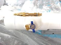
In this picture, you can see the final set up. The top fittings, from left to right, are: male air attachment, check valve, T-fitting (screws into cap), and vent (opened while filling, closed otherwise). On the bottom, you can see the drain valve.
IMG_20160925_134553.jpg

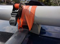
And that was it - the tank was done, and worked perfectly! So I painted everything gloss white (People in canada paint tanks black. If I did that here, I'd scald someone to death.) Now, since I want it to stay with the car while I'm driving it around, I needed to figure out how to mount it. This turned out to be pretty simple: I acquired a pair of canoe gunwale pads and cut them so that the tank sat securely in them, then hacked a couple of ratchet straps to fasten everything in place.
IMG_20170128_153014.jpg

A nice NSF grade 10 foot hose and a hose sprayer were procured from amazon, and now we are in business!
IMG_20170128_153331.jpg
I keep a small in-line regulator in the car, and I use it to limit the air pressure inside the tank to 40 PSI.

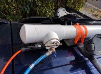
Here's the whole system, mounted:
IMG_20170128_153048.jpg

User testing is a success! Another successful build!
 

Attachments

  • IMG_20160915_105356.jpg
    IMG_20160915_105356.jpg
    141.9 KB · Views: 1,940
  • IMG_20160925_134553.jpg
    IMG_20160925_134553.jpg
    117.6 KB · Views: 1,971
  • IMG_20170128_153014.jpg
    IMG_20170128_153014.jpg
    127.4 KB · Views: 1,984
  • IMG_20170128_153331.jpg
    IMG_20170128_153331.jpg
    129.9 KB · Views: 1,979
  • IMG_20170128_153048.jpg
    IMG_20170128_153048.jpg
    142.6 KB · Views: 2,029
Last edited:
GoPro Self-spotting

This is kind of a weird one, and might not really deserve to be called a "mod", but here it goes.

Some of my friends and I were about to head out on a two day trip around Mauna Kea, and I decided that I wanted to make a time-lapse video of the whole trip. I've got a GoPro, and a couple of spare batteries, so the only real question was how I was going to mount the thing so that it looked good.

There's lots of nice mounts out there that clamp onto roof racks, etc, but I was leaving now. The quick and dirty solution: use one of the standard GoPro stick-on flat surface mounts.
IMG_20170212_161220-800.jpg
There we go!

The time-lapse was kind of meh - but I should have done every 2 seconds, rather than every 5.

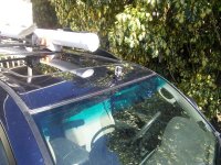
But this got me thinking: What if I wanted to see whatever my tires were about to hit? This should be easy to do with a GoPro - they can connect to a mobile device and give you a live view of what is going on. All I have to do is put the camera in the right place:
IMG_20170212_161326-800.jpg

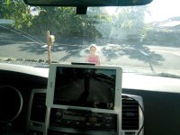
And then connect it to my el cheapo tablet:
IMG_20170212_162255-800.jpg

And here's what the tablet sees:
Screenshot_2017-02-12-16-23-09.jpg
Modern technology in action! Wireless for the win!

Note that a little configuration in the settings reduces general aggravation: activate developer mode, then setting "stay awake" while charging to on will ensure that the tablet keeps things from powering down while I'm focusing on other things.

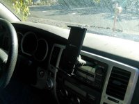
The car mount is a Satechi Universal Mount that actually grips the slot of the CD player. I don't use the CD player at all (More on that in a future post!) but you can actually use a loaded CD while the mount is in place:
IMG_20170212_161241-800.jpg

To Do: I still want to figure out a way to power the camera so that I don't have to change batteries, but that's a project for another day.
 

Attachments

  • IMG_20170212_161220-800.jpg
    IMG_20170212_161220-800.jpg
    83.1 KB · Views: 1,767
  • IMG_20170212_161326-800.jpg
    IMG_20170212_161326-800.jpg
    66.3 KB · Views: 1,745
  • IMG_20170212_161241-800.jpg
    IMG_20170212_161241-800.jpg
    50.8 KB · Views: 1,736
  • IMG_20170212_162255-800.jpg
    IMG_20170212_162255-800.jpg
    51.3 KB · Views: 1,729
  • Screenshot_2017-02-12-16-23-09.jpg
    Screenshot_2017-02-12-16-23-09.jpg
    82.3 KB · Views: 1,871
Last edited:
Hi-Lift Jack Handle Keeper

After this weekend's off-road trip, I decided that I was finally sick enough of listening to the Hi-Lift jack rattle to do something about it. Hi-lift sells a retainer, but I decided that charging $17 for a single plastic piece was a mere finger's-breadth from qualifying as highway robbery.

Yes, I know you can buy these, but what's the fun of having a 3d printer if you can't use it?

Anyhow, I could print my own for $1.84 in materials.* Plus, I wanted something that was a bit easier to attach and remove, so I made my own. The first attempt was a bit loose, but Rev 2 was just about perfect.

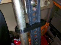
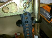
Here's the final item:
IMG_20170213_202935-800.jpg
IMG_20170213_202950-800.jpg

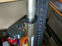
Here you can see the geometry that keeps the clip from sliding up or down the beam once engaged.
IMG_20170213_203012-800.jpg

And, for those of you who are obsessed and have your own printers, here's the files:
View attachment Hi-Lift Jack Clip R2.zip

* For the record, if you count the cost of my time and the machine time, it was a total loss. But "anything worth doing is worth over-doing" as I love to say.

P.S. On the off chance that any of you decide to print your own, there's print info available on my thingiverse.com page, and I'd appreciate reviews that people are willing to share.
 

Attachments

  • IMG_20170213_202935-800.jpg
    IMG_20170213_202935-800.jpg
    46.2 KB · Views: 1,724
  • IMG_20170213_202950-800.jpg
    IMG_20170213_202950-800.jpg
    52.5 KB · Views: 1,722
  • IMG_20170213_203012-800.jpg
    IMG_20170213_203012-800.jpg
    45.6 KB · Views: 1,716
  • Hi-Lift Jack Clip R2.zip
    Hi-Lift Jack Clip R2.zip
    108.4 KB · Views: 323
Last edited:
HAM Radio Install - Part 1: That "planning" thing

Before I sold the Subaru Outback, I pulled out the HAM radio that I'd painstakingly wired in, "saving it for later". That radio has been sitting in my garage for two years now, waiting for me to figure out how to get it into the 4Runner. It's time.

For the record: I'm not a fan of hacking big holes in a car to mount new equipment - With the exception of things that can't possibly be hidden, like roof racks and suspension/tire upgrades, I want the car to look stock from without. I also want to be able to remove things in the future without leaving gaping holes or other damage anywhere. Drilling holes in the exterior surfaces is only an option of last resort.

So, before I did anything to install the radio, I wanted a good idea of how the wiring was going to run, where each bit was going to live, and how I was going to get it that way.

So here's what I need to get mounted:
  • Radio head unit, to which the mic attaches,
  • Radio body unit, which has connections for power, antenna, and external speakers.
  • Antenna
A note about the Radio head and body units: These can be mounted together, but with an RJ45 cable, you can mount the head unit remotely, perhaps on your dash, and have the body located somewhere else, like under a seat. The result is a much lower profile install.

Let's start with the antenna:
I have a Comet CA-2X4SR. This is a dual-band antenna that is designed for use with most common VHF and UHF Search and Rescue frequencies.

I want this to be located in a place that maximizes my ability to transmit and receive, which means higher is better, and if I can mount it above a flat metal surface that will act as a ground plane, so much the better! That would be the roof. I also don't want to be ripping it off every time drive into a parking garage or under some tree branches, so it better have a "stowed" position, ideally one that allows for normal transmit and receive operation, even if the radiation pattern isn't ideal. The easy solution: A Diamond K550 mount. This mount attaches nicely to the stock roof rails (someday I will have a "real" roof-rack, someday . . .), and offers lots of adjustability, and easy raising and lowering of the antenna.

Resolved: The Comet CA-2X4SR will be mounted on the roof rails using a Diamond K550 mount. The exact location will be determined based on cable lengths. Off we go.

The next step is figuring out where the radio body unit will be mounted. This is the heart of the install - all the other parts connect to this component. The options for this are:
  • Attached to the head unit, wherever that may be (in a footwell, or something like that) - I'm not a fan of this option - all the possibilities here have a serious downside - putting things on the dash is ugly, and can't be hidden, in the footwell results in equipment that is hard to reach (except with my shins), or is so bulky that it impedes normal use of other features.
  • In the center console - Again, not a fan, I keep lots of useful crap in the console armrest container, and if it's not something I want to be able to pull out and use frequently, I don't want to put it in there if I can possibly put it somewhere else.
  • Under a seat - This could work. The one downside is that the body has a speaker in it, and there are some advantages to having a speaker in the rear of the car. Let's keep this in mind.
  • Exposed in the rear cargo area - No likey. Exposed equipment will be abused, and if I have any other option, I'd rather use it. On the other hand, there is a power port back here that I can tap.
  • Behind one of the rear cargo panels - The left-hand panel is filled with the jack, tire kit, an air line, etc, which works well and I don't want to mess with, but the right-hand (larger) panel has really potential. It's large enough, and the accessory power circuit is in that panel, so I wouldn't have to run new wire all over creation (yet. Actually, it's recommended that radios not be powered off of the accessory circuits, since they tend to be noisy. However, I'm going to put a second battery into the truck at some point, and I think I'll run a large power line to a fusebox in this cargo panel anyway, so I can re-wire the radio power then.) In addition, there's a wiring harness that runs from behind this panel under the door sills on the passenger side, which leaves plenty of room for me to run the head unit's RJ45 cable to the front of the car. We have a winner!

Finally, that leaves the head unit.
As I said at the beginning of this post, I like mods to be hidden from the casual eye.
I don't like having things mounted on the dash, so that'll only happen as a last resort.
I've also never been impressed with mounts where the head unit is on the side of the front console (near the foot well). I always felt like things would get caught, or the unit would get kicked, or my shins would hate me.
There's not sufficient space in the radio stack
Putting in a passenger-side gooseneck certanily keeps things accessible, but would not be so good for my marriage.
I could put it in the cupholder that so many people hate, except that I like that thing. It fits my Nalgene and hydroflask bottles perfectly!
So, by process of elimination, the head unit is going inside the center console storage area. Bonus: there's an AUX jack here - I can probably plug the radio into the whole vehicle's sound system!

Okay, now I know where everything is going. It's time to do the work.
 
HAM Radio Install - Part 2: The main radio body

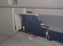
The radio body unit is the central component to the whole system. Everything (the antenna, power, head unit) hooks into it. As discussed previously, I'm going to install it in the right-hand rear cargo panel.

The first step is figuring out power. As I mentioned earlier, built-in accessory power circuits tend to be noisy, and are generally not recommended for powering radios. Too bad. I'm using it anyways until I have a second battery installed and can run some REAL POWER back there.

The first step is to take the whole back end apart. Apparently this panel is installed early in the assembly process, which means that I have to take out a ton of stuff before I can get it off. I've got to take out the cargo deck, the tie-down points, the rear hatch sill, and the seatbelt. Then, I have to extract the little cargo pocket over the wheel-well. It's a total PITA, but whetever.

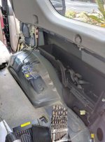
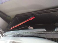
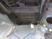
In the lower right corner, you can see the connector that powers the rear accessory power port. In the upper right, you can see the wiring harness that goes around this cargo pocket, then heads down under the door frame towards the front of the car. I'll be running my remote head unit cable, and an audio cable that will hook into the truck's AUX input.
IMG_20161011_131244-800.jpg

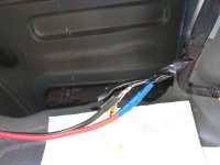
I cut a notch in the remaining plastic "bathtub" to pass the cables through. The black cable toes to the remote head unit, and some zip-wire with a set of PowerPoles (Best electrical connector for hackers, possibly ever. To know them is to love them. Also, if you are into Amateur Radio, there's really no excuse not to be familiar with them.) I'll also run a 10 ft audio cable through the notch, which will follow the black cable.
IMG_20161011_133425-800.jpg

Here I've exposed some of the wiring for the accessory port.
IMG_20161011_133435-800.jpg

Solder things together, cover them with electrical tape, and we're good to go!
IMG_20161011_135406-800.jpg
The power port will still function as advertised, but I probably shouldn't TX on high power while running high-drain stuff . . .

The future battery system will solve all those problems, I am sure!

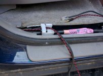
A little finagling gets the cables all into the cable run under the rear passenger-side door sill, then on to the front.
IMG_20170120_085322-800.jpg

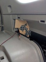
Now all the cables are in place, so the next problem is actually mounting the body unit. Screwing into panels is a measure of last resort, so I decided to build 3D print a bracket that held the radio nice and securely in there. Some double-sided foam tape holds it in quite firmly, no screws required.

Some cardboard scraps and duct tape help make a template for the space, which I can then measure and model up in CAD.
IMG_20170120_144939-800.jpg
Batman duct tape is obviously superior to ordinary duct tape, for all the reasons that you might imagine.

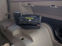
The printed bracket snaps right onto the existing mounting bracket.
IMG_20170121_072103-800.jpg

And finally, here's everything back in place. The foam tape, which you can't see in this picture, holds everything in quite firmly.
IMG_20170121_072134-800.jpg

While I've tested all the wiring, I'm leaving things unplugged until everything is assembled.
 

Attachments

  • IMG_20161011_131244-800.jpg
    IMG_20161011_131244-800.jpg
    53.2 KB · Views: 1,669
  • IMG_20161011_133425-800.jpg
    IMG_20161011_133425-800.jpg
    32.3 KB · Views: 1,647
  • IMG_20161011_133435-800.jpg
    IMG_20161011_133435-800.jpg
    40.4 KB · Views: 1,678
  • IMG_20161011_135406-800.jpg
    IMG_20161011_135406-800.jpg
    29 KB · Views: 1,681
  • IMG_20170120_085322-800.jpg
    IMG_20170120_085322-800.jpg
    52.2 KB · Views: 1,682
  • IMG_20170120_144939-800.jpg
    IMG_20170120_144939-800.jpg
    27.8 KB · Views: 1,667
  • IMG_20170121_072103-800.jpg
    IMG_20170121_072103-800.jpg
    30.4 KB · Views: 1,651
  • IMG_20170121_072134-800.jpg
    IMG_20170121_072134-800.jpg
    24.5 KB · Views: 1,725
HAM Radio Install - Part 3: Head unit

As discussed in the first post in this series, I decided to put the head unit in the center console storage. This keeps things neatly contained, out of the way most of the time, and keeps people from deciding that my cheapo radio is worth breaking a window for.

I had originally envisioned a complicated mechanism that would lever out the the console storage and make the radio accessible when the lid was closed, but I decided in the end that it would be too complex, too expensive, and take too long, so I've moved on. For now. I've still got all the CAD design files, so it may happen someday, but don't hold your breath.

Instead, I decided to go with something a bit simpler that only requires a single additional part, and I can make that part with my 3D printer.

The first step was to get the cables (remote head unit and audio) up into the center console. This, of course, requires taking the whole console apart. Other people have covered how to do this, so I'm going to skip those details here.

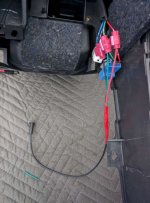
As you may recall from Part 2, I'd already run these up the cable run under the door sills on the passenger side. The next step was to run them under the carpet up into the center console area. A fishtape and some string solved this problem quite nicely.
View attachment 241832

The only cable that really matters is the RJ45 remote head unit cable - the radio will work fine with only it connected. But, since I can't leave well enough alone, I decided that I wanted to tie the radio into the truck's audio system. To do this, the "speaker out" port on the main radio body is getting connected to the AUX input using the long audio cable I've previously referred to. I have other plans for the AUX jack (just you wait!) so the solution is to tap the audio lines and add in another jack that will stay hidden inside the center console. I went down to the local Auto-Audio store, and asked what they had, and the guy rummaged around in the back for a while before finding this random pigtail. It apparently came from an aftermarket system designed for Jeeps, so I performed a ritual of purification and put it in a bag of sage for 24 hours before using it.
IMG_20170120_124349-800.jpg
Note that it's important to get all the wires connected correctly. I went through with a multimeter several times before I actually tapped into any lines. I also found out something interesting: the AUX jacket has an activation circuit (which is why you can't open AUX on the built-in radio unless there's something plugged into the AUX jack). I haven't spent the time to bypass this since I leave something plugged into the jack all the time anyhow. No worries.

The sound cables are going to stay out of the user-accessible areas, but the RJ45 needs to come into the console storage area. I could drill a hole, or just pop off the little cover that isn't being used to provide a USB power port. (Did I mention that I have an SR5? No worries, I have plans for a super-duper USB solution. Come back soon for more details!) This gives me a nice clean entry point for the RJ45.

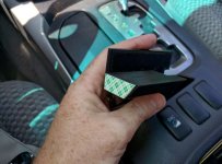
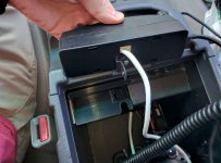
With the cabling all dealt with, it's time to get the head unit mounted. I need to be able to remove the head periodically to reprogram the radio, but I want things to be secure under normal use. The solution was to print a bracket that sits in the right place (again secured with double-stick tape).
IMG_20170303_122034-800.jpg

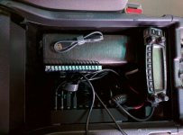
It fits right in to the console storage box. You can also see how the radio bracket fits in.
IMG_20170303_122537-800.jpg

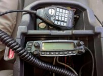
Here's the final fit:
IMG_20170303_122602-800.jpg

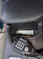
If desired, I can pull out the speaker/mic and close the console lid - there's enough of a gap that the cable doesn't get crunched.
IMG_20170303_122645-800.jpg

There we have it! Next, and final, step: the Antenna!
 

Attachments

  • IMG_20170120_124349-800.jpg
    IMG_20170120_124349-800.jpg
    55.7 KB · Views: 1,667
  • IMG_20170303_122034-800.jpg
    IMG_20170303_122034-800.jpg
    39.9 KB · Views: 1,659
  • IMG_20170303_122537-800.jpg
    IMG_20170303_122537-800.jpg
    45.3 KB · Views: 1,694
  • IMG_20170303_122602-800.jpg
    IMG_20170303_122602-800.jpg
    59 KB · Views: 1,666
  • IMG_20170303_122645-800.jpg
    IMG_20170303_122645-800.jpg
    54.3 KB · Views: 1,636
Last edited:
HAM Radio Install - Part 4: Antenna

The final chunk of getting this whole shebang on the air is getting the antenna mounted. As I mentioned earlier, I'm using a Comet CA-2X4SR antenna and a Diamond K550 luggage rack antenna mount.

The antenna mount comes with a limited amount of coaxial cable, and splicing in the antenna feeds opens a whole can of worms in terms relating to how well your radio transmits, as opposed to heating things up, so I'm not doing it. (I could calculate the proper base cable length based on the frequencies that I'm operating in, then cut a multiple of that, but I'm not that bored yet)

What this means is that I'm putting the mount in the best place that the cable can reach to. Bear with me for a minute.

The radio body is located behind the right cargo panel (on the right-hand side of the vehicle, in the rear). Ideally, I'd have the antenna mount right over the driver's window (on the left-hand side of the vehicle, in the front), as then I could just reach out the window and raise or lower the antenna without getting out of the vehicle. This is the configuration that requires the absolute maximum amount of cable, and more cable than I have available. Oh well.

Given that I can't reach that far and still be lazy about this project. My second choice is that the antenna mount be on the driver's side of the vehicle. There are two reasons for this:
  1. I want the antenna mount to be as close as possible to the driver when they get out of the vehicle.
  2. I move a kayak around on the roof frequently, and it gets loaded from the passenger's side of the vehicle. Loading a heavy kayak over the antenna sounds like a couple sort of bad planning.
So, the best I can do at the moment is to have the the antenna mount over the driver's side door for the second row sets. (Just in front of the rear cross-bar.)
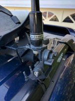
IMG_20170305_101126-800.jpg

The downside of this is that when the antenna is in the lowered position, it points forward, which means that there's the potential for things to get caught in it easily, which would probably destroy the antenna. It also rattles something awful when I'm going over rough spots.

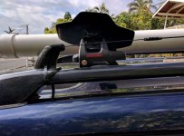
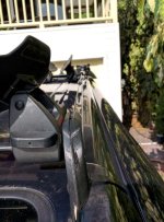
I'm going to forestall all of this by making a bracket that holds the tip of the antenna captive and acts as a guide to prevent things from getting caught under the antenna. A bit more time in Solidworks and on the 3D printer, glue the two halves together, and we're set!

The view from the side:
IMG_20170305_155530-800.jpg

The view from the front:
IMG_20170305_155601-800.jpg

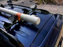
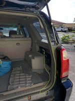
At this point, all that's left is getting the cable routed. Here's a view from the top. The cable path is highlighted in green.
IMG_20170305_160949 - Edited-800.jpg

Here's the view from the back, with the hatch open.
IMG_20170305_161053 - Edited-800.jpg

Finally, we're done! Hook up the antenna, power, audio, and the whole thing actually works! Hurrah!
IMG_20170305_161116-800.jpg

And . . . that's it! Mod done!
 

Attachments

  • IMG_20170305_155530-800.jpg
    IMG_20170305_155530-800.jpg
    50.4 KB · Views: 1,009
  • IMG_20170305_155601-800.jpg
    IMG_20170305_155601-800.jpg
    54.1 KB · Views: 1,008
  • IMG_20170305_101126-800.jpg
    IMG_20170305_101126-800.jpg
    44.4 KB · Views: 1,373
  • IMG_20170305_160949 - Edited-800.jpg
    IMG_20170305_160949 - Edited-800.jpg
    59.5 KB · Views: 1,009
  • IMG_20170305_161053 - Edited-800.jpg
    IMG_20170305_161053 - Edited-800.jpg
    51.2 KB · Views: 1,012
  • IMG_20170305_161116-800.jpg
    IMG_20170305_161116-800.jpg
    32.1 KB · Views: 1,062
HAM Radio Install - 3D printer files

For those that want them, here are the files that I used to print parts for installing my Ham Radio.

I couldn't compress the Mounting block enough that I can upload it here to the forum, but here's a link to the file on thingiverse.
 

Attachments

Last edited:
Periodic Maintenance

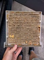
I guess these "cabin air filters" should be changed occasionally, yeah?
IMG_20170309_123629-800.jpg
 

Attachments

  • IMG_20170309_123629-800.jpg
    IMG_20170309_123629-800.jpg
    69.2 KB · Views: 909
All your USB are belong to us

Like any 21st century technophile, I have a mobile phone. So does my wife. I also have a tablet, and a GoPro, and a few other things that charge via USB. Off the top of my head, I can think of 8 items that I would reasonably expect might come on a long trip that charge via USB. My truck (SR5), on the other hand, has zero built in USB charging ports. :(

Yes, I know about the cigarette plugs. :deadhorse:

Yes, I know you can get a little gizmo that plugs in there and charges things. The problem is that there are two power ports, one in the console, and one in the cargo compartment. The former makes a mess of cords in the front seat, and the latter is d@mn near inaccessible when I need it.

What I REALLY need* is a bunch of USB ports in an easily accessible spot where all the charging gizmos are conveniently contained, and are accessible form the front seat. Bonus points if:
  • Includes several high-power charging ports
  • Includes LOTS of ports
  • Does not require drilling or other permanent damage to the car
  • Does not require extensive rewiring of anything
See, I'm easy to please.

* My wife suggests therapy. :loco:

There's a bunch of REALLY EXPENSIVE USB hubs that are specifically designed for automotive use. Lots of them use words like "ruggedized" and "Mil-spec" are frequently mentioned, which are synonymous for $$ and $$$, respectively.
Call me crazy, but I wasn't ready to drop $300+ for some of these units.

As it turned out, the item I wanted in the car has been sitting on my desk for nearly a year. Anker makes a 7 port USB hub that has three additional high-power charging ports. The one on my desk had a 12V wall wort, which got me thinking: many DC electronics are actually designed to accept a fairly wide range of voltages. This gizmo might be able to be wired directly to the vehicle's power system!

This sounded like it might possibly work, but of course nothing like this is listed in the manual or tech specs. What to do? Call Anker's customer support to ask them!

They did not understand (could not wrap their brains around) what I was asking at first, which is always good for a laugh. :wacko: Once they realized I was serious :nod:, they realized that they didn't know :confused:, so they suggested that I send an email to the support team, which might include actual engineers :nerd:.

After some back in forth with the support team ("We don't recommend using this device in cars!" and "I know this isn't "recommended", look, can you answer the voltage question?") they told me that the A7515 model is designed to accept voltages from 9V to 20 V. Which is PERFECT. It conveniently covers the 11 - 14.5 volts that I expect to find in an automobile, and gives me a bit of breathing space as well. We're in business! There was one little hiccup: It was a bit disappointing that Anker wouldn't ship to Hawaii at all (you know that Hawaii is a US state, right?), but there's always Amazon Prime!

Two weeks later . . . . (Seriously, Hawaii ain't all paradise. Getting goodies shipped here, even by Prime, is a real drag.)

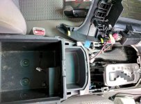
By the time the Hub got here, I had figured out where I wanted it to go: in the center console storage area. This meets all of my requirements from above, and lets me take advantage of the wire routing I used for the radio (see earlier posts).

ACTUAL BUILD STARTS HERE!

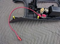
So seeing as I want to hook it up to 12V power, but don't want to run lots of wires around, I simply pulled off the trim piece with the power port in it, tapped into the power lines for the port and wired in some PowerPoles. Easy!
IMG_20170120_125929-800.jpg

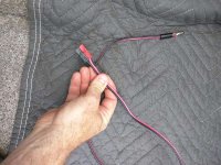
Then I wired up a wiring harness with a 5.5 mm DC jack on one end, and a set of PowerPoles on the other.
IMG_20170120_121246-800.jpg

This was run alongside the same path that I used for wiring the radio head unit, and viola! it is done.
IMG_20170120_130314-800.jpg
Further, it works!

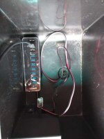
I spent a while with the unit just bouncing around at the bottom of the center console storage, but after a while, some double-sided foam tape was used to fasten it in a convenient location.

Before:
IMG_20170120_131649-800.jpg

After:
IMG_20170416_133551-800.jpg

Done!

Interesting note:
This unit is designed to be used as a USB hub - that is, it's normally used while connected to a computer. When used this way, all the devices in the 7 full-function ports then do their thing, and charge at normal rates. However, according to the USB specification, if the hub is not connected to a computer, all devices should STILL CHARGE THE WAY THEY ARE INTENDED TO. Interestingly, there are a fair number of devices, especially cell phones, that don't implement the USB spec in exactly this way. Some devices will realize that no computer is connected, then shut down the connection, and won't even charge (which is stupid). These devices will usually charge fine on dedicated charging ports, though. :shrug: So if you do this, just test things out and make sure that devices are actually charging.
 

Attachments

  • IMG_20170120_121246-800.jpg
    IMG_20170120_121246-800.jpg
    77.6 KB · Views: 877
  • IMG_20170120_130314-800.jpg
    IMG_20170120_130314-800.jpg
    61.3 KB · Views: 892
  • IMG_20170120_131649-800.jpg
    IMG_20170120_131649-800.jpg
    41.6 KB · Views: 884
  • IMG_20170120_125929-800.jpg
    IMG_20170120_125929-800.jpg
    62.2 KB · Views: 889
  • IMG_20170416_133551-800.jpg
    IMG_20170416_133551-800.jpg
    49 KB · Views: 876
Last edited:
Bluetooth Audio Integration

Well, I was installing a bunch of other electronics, and I came across this little gem: the Anker "SoundSync Drive" Bluetooth Adaptor
A3351011_TD01.jpg


Now that I have the USB ports, right in the console where the AUX in port is located, it's hardly worth calling this a mod - I simply plugged the thing in.

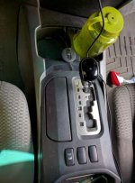
The only real question was where to mount the puck. After some thinking, I ran the wire under the center console and have the puck sitting right on the center divider for the cupholder.
IMG_20170416_135854-800.jpg

A little configuration of my Android phone and we're in business. Here's what I've got going on:
Now, the phone connects whenever I start the car, and plays through the AUX setting on the radio.

There is some alternator whine on the line, which I'm going to have to take care of, but that's a project for another day. (I'm open to suggestions if you have an easy to deal with it!)
 

Attachments

  • IMG_20170416_135854-800.jpg
    IMG_20170416_135854-800.jpg
    53.5 KB · Views: 1,065

Members online

Forum statistics

Threads
278,307
Messages
3,554,054
Members
248,016
Latest member
Advally Service

Trending content

Back
Top