McCand's Build Thread

I've run through a tank of gas since they've been installed, and my gas mileage has definitely taken a bit of a hit. The new KO2s are also substantially heavier than the old tires, so there's a noticeable change in the handling (acceleration in particular) of the car. It's not a problem, just noticeably different.

Anyhow, we'll see how things go: I've got a off-road camping trip this weekend...
Fwiw, when I switched to my new tires I saw quite a hit too. Then someone asked if I was still running them at 35 psi, which I was. He suggested increasing the psi to 40 and my mileage is now almost the same as it was before. Apparently, you have to run higher psi for e rated tires.
 
Mine were all set to 45 psi when they were installed, so I'm not sure what the deal is. I guess this is why we say "Your Mileage May Vary"...
 
Rear Storage System - Part 3 - Drawer Build

Well, I've been delaying work on this project for one reason or another for too long, but I had a 4x4 camping trip come up that finally spurred me to get things done.

As I've said earlier, I want to impose some level of organization on the huge pile of stuff that winds up in the rear of my 4Runner.

I also want a sleeping platform. Since that will help get the wife out on camping adventures. The Centipedes here are really amazing.

Oh, I also want it to look good.

So in a previous post, I had worked up a design for a system that I though met my requirements.

After letting things turn over in my mind for a while. I've made a plan, which includes some changes to the design shown previously.
  1. I'm changing the cabinet sites to be sheet metal
  2. I'm revising the sleeping platform design from hinged panels to lift-away panels.
  3. I've adjusted some material thicknesses.

Changing cabinet sides from wood sides (1/2" thick) to metal (1/16" thick) actually increases the storage volume significantly. (It allows each drawer to be 7/8" wider inside. The dimensions of the drawer side are 10.25 x 35.5. There are 2 drawers. Multiply all these number together, and you get 637 cubic inches of space back. That's about 2.75 gallons of space.)

The hinged panels were not really a great solution. In theory, they would have been able to be folded into place directly, but in practice it would be difficult to make them move nicely around the roof, C pillars, and various hardware while still making a nice wide platform. Moving away from the hinged panels reduces complexity, and reduces the need for additional structure to prevent the joint from failing when loaded. It also reduces hardware cost!

So, Here's a general list of parts and quantities:
  • Starboard-side (large)
    • Large Cabinet
      • 1 x Left side (metal)
      • 1 x Right side (metal)
      • 2 x 36" drawer sliders
      • 1 x Back panel (1/2" wood)
      • 1 x Top panel (3/4" wood)
      • 1 x Starboard platform wing panel (3/4" wood)
      • 1 x Starboard wheel well panel (3/4" wood)
      • 3 x "Sewing machine" hinges
      • 1 x Long mounting flange
    • Starboard side drawer
      • 1 x Drawer Face panel (3/4" wood)
      • 1 x Bottom panel (3/4" wood)
      • 1 x Rear panel (1/2" wood)
      • 2 x Side panel (1/2" wood)
      • 2 x Drawer Face mounting blocks (3/4" wood)
    • 1 x Starboard Extension panel
  • Port-side (small)
    • Small Cabinet
      • 1 x Left side (metal)
      • 1 x Right side (metal)
      • 2 x 36" drawer sliders
      • 1 x Back panel (1/2" wood)
      • 1 x Top panel (3/4" wood)
      • 1 x Port platform wing panel (3/4" wood)
      • 1 x Port wheel well panel (3/4" wood)
      • 3 x "Sewing machine" hinges
      • 1 x Short mounting flange
    • Small drawer
      • 1 x Drawer Face panel (3/4" wood)
      • 1 x Bottom panel (3/4" wood)
      • 1 x Rear panel (1/2" wood)
      • 2 x Side panel (1/2" wood)
      • 2 x Drawer Face mounting blocks (3/4" wood)
    • 1 x Port Extension panel

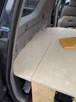
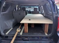
So the first decision was how HIGH to make the the drawers. I found that if I made the bottom side of the sleeping platform 12 inches up from the baseplate, it cleared the wheel wells with a bit to spare and the forward panels (sleeping platform extensions) would rest nicely on the folded up second-row seats, creating a level platform from front to back. This let me start cutting panels for the sleeping platform.

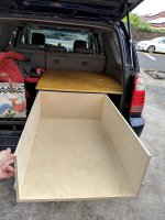
I started with the Starboard cabinet top pieces and bed extension panel:
2457992929559541300-800.jpg

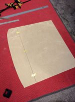
Being picky really makes life complicated. I had decided that I wanted the platform to extend neatly to the edges of the available space (so that things can't drop down into crevices). This meant that some parts, like the extension and wing panels are highly contoured. Of course, there's no pattern available for these, so I needed to do quite a few cycles of "Test fit, mark, sand" to get parts to fit right.

After getting these pieces cut, sanded, varnished, and hinges installed...
IMG_20171106_134815-800.jpg
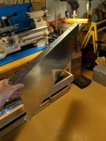
...I really couldn't do more (useful) work until I had the cabinet sides. As I mentioned before, I had decided to go with metal sides. So I went to a local shop that specializes in HVAC and architectural metal parts, and had them whip up four pieces out of 16 gauge galvanized steel. A few days and $250 later, I brought the parts home:
IMG_20180402_190314-800.jpg

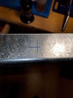
Marked them:
IMG_20180402_190333-800.jpg

Drilled them:
IMG_20180402_190340-800.jpg

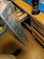
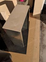
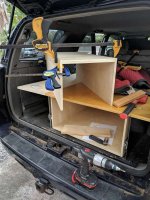
And then did some test assembly:
IMG_20180405_173609-800.jpg
IMG_20180406_153334-800.jpg

The next step was to get the drawer slides installed. This turned out to be more complicated than I thought. The drawer slides are designed to be attached to a wood or wood-like material, using wood screws. Since I was using a 1/16" thick steel panel, there wasn't room for much thread engagement, and I didn't want nuts or washers sticking out on the outside anyways. Plus, there wasn't much space on the inside either!

The solution: Solid rivets!

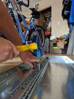
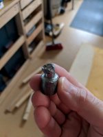
I'll be honest, I hadn't done much work with solid rivets before (I'm more used to pop rivets). I knew that you had to hammer them down some how, but how hard could that be. Combining this lack of practical experience with no restraint in material selection resulted in me having a box of Stainless Steel Rivets. It turns out that these are EXTREMELY hard to hammer down - most folks use a hydraulic press. So I want and talked to a guy at a local machine shop, who was willing to give this a try. There was the added complication that the tail end of the rivet was on the INSIDE, where the drawer slide is, so I was going to have to access this through the access holes in the drawer slide. So I made a little punch out of mild steel, which could be used to press down the rivets.

It didn't go well.
IMG_20180419_094538-800.jpg

The rivets were significantly harder than my punch, and quickly destroyed it. The solution was to use a more suitable material, so I ordered a pack of ALUMINUM rivets.

 

Attachments

  • 2457992929559541300-800.jpg
    2457992929559541300-800.jpg
    45 KB · Views: 359
  • IMG_20171106_134815-800.jpg
    IMG_20171106_134815-800.jpg
    36.6 KB · Views: 345
  • IMG_20180402_190314-800.jpg
    IMG_20180402_190314-800.jpg
    50.8 KB · Views: 351
  • IMG_20180402_190333-800.jpg
    IMG_20180402_190333-800.jpg
    37.9 KB · Views: 344
  • IMG_20180402_190340-800.jpg
    IMG_20180402_190340-800.jpg
    41.2 KB · Views: 341
  • IMG_20180405_173609-800.jpg
    IMG_20180405_173609-800.jpg
    42 KB · Views: 365
  • IMG_20180406_153334-800.jpg
    IMG_20180406_153334-800.jpg
    64.7 KB · Views: 332
  • IMG_20180419_094538-800.jpg
    IMG_20180419_094538-800.jpg
    27.5 KB · Views: 354
Rear Storage System - Part 4 - Cabinet Build (Continued) and Baseplate Modifications

So the new aluminum rivets were much easier to work with. They are certainly not as strong, but until proven otherwise, they seem strong enough.

The drawer sides had already been drilled and countersunk for the rivets, so the slides were set in place, then hammered over with a new punch.
IMG_20180418_140437-800.jpg

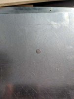
This worked much better, and I didn't need a hydraulic press! Here's what the rivets look like from the outside:
IMG_20180408_172157-800.jpg

Not too shabby!

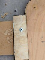
The next step was to make some modifications to the baseplate. I needed to add a way to mount the cabinets to the baseplate, so I marked out some desired screw locations, pulled it out, drilled the holes and installed some M8 hammer-in T-nuts.
IMG_20180425_101527-800.jpg
(I actually ended up using two sizes. most of the baseplate is 3/4" thick, but the aft edge was thinned out to rest on the existing trim. Refer to my baseplate build post for further information.)

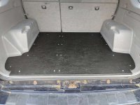
Once those were in place, I put a chamfer on the aft edge of the baseplate since that corner had been taking a lot of abuse, cut away some of the forward edge that had been catching on the second row seat, put a new coat of paint on, installed screws, and reinstalled it in the truck.
IMG_20180425_171646-800.jpg
 

Attachments

  • IMG_20180418_140437-800.jpg
    IMG_20180418_140437-800.jpg
    52.4 KB · Views: 333
  • IMG_20180408_172157-800.jpg
    IMG_20180408_172157-800.jpg
    34.1 KB · Views: 334
  • IMG_20180425_101527-800.jpg
    IMG_20180425_101527-800.jpg
    41.8 KB · Views: 339
  • IMG_20180425_171646-800.jpg
    IMG_20180425_171646-800.jpg
    52.1 KB · Views: 336
Rear Storage System - Part 5 - Drawers and Finishing Touches

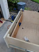
With the cabinets and baseplate all in their final forms, the next step was to put some drawers together, after measuring once and cutting twice (embarrassing, I know), I had the drawer frames ready to go. With some careful shimming, they were attached to the drawer slides:
IMG_20180419_135417-800.jpg
IMG_20180420_161559-800.jpg

The skeleton of the Port Cabinet was added in:
IMG_20180419_183101-800.jpg

In order to avoid screws visible on the drawer faces, I used mounting blocks to attach them to the rest of the drawer:
IMG_20180421_180220-800.jpg

With the drawers built, I finished cutting and sanding the remaining parts for the sleeping platform.
IMG_20180428_105406-800.jpg

Then a started varnishing things! Everything got at least two coats of varnish, and then the top surfaces of all the sleeping platform parts got an additional coat with some "Seal-krete(TM) Non-Slip Grit Additive". This adds a little bit of roughness to the parts and should make it so that things don't slide around too much.

Once the varnish was dried, I installed the battalion latches, and we were good to go!

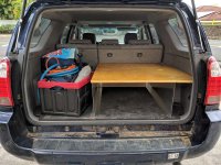
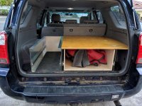
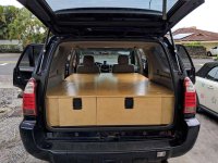
Here's the whole thing, in Bed configuration:
IMG_20180504_145907-800.jpg

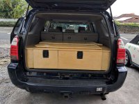
This shows the extension panels stowed in the back so that the rear seats can be up. I put some felt sliders on the bottom of these panels. Combined with the grit in the varnish, they stay right were I put them, which is pretty glorious.
IMG_20180504_153630-800.jpg

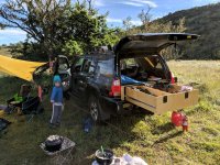
And the Final Test:
IMG_20180506_073513-800.jpg

It was awesome! They worked great over a two day trip. I'll keep 'em!

For day-to-day use though, I'm probably just going to leave the port (driver) side cabinet in place. That gives me plenty of space to store regular equipment and such. If I want to have the whole shebang, I can bolt the other cabinet in place in about 10 minutes - less with another set of hands to help.
 

Attachments

  • IMG_20180419_135417-800.jpg
    IMG_20180419_135417-800.jpg
    54.9 KB · Views: 349
  • IMG_20180419_183101-800.jpg
    IMG_20180419_183101-800.jpg
    59.9 KB · Views: 355
  • IMG_20180420_161559-800.jpg
    IMG_20180420_161559-800.jpg
    67.5 KB · Views: 358
  • IMG_20180421_180220-800.jpg
    IMG_20180421_180220-800.jpg
    52.5 KB · Views: 370
  • IMG_20180428_105406-800.jpg
    IMG_20180428_105406-800.jpg
    37 KB · Views: 349
  • IMG_20180504_145907-800.jpg
    IMG_20180504_145907-800.jpg
    61.4 KB · Views: 349
  • IMG_20180504_153630-800.jpg
    IMG_20180504_153630-800.jpg
    58.9 KB · Views: 350
  • IMG_20180506_073513-800.jpg
    IMG_20180506_073513-800.jpg
    94.7 KB · Views: 350
Rear Storage System: Part 6 - Future work

For all that I'm thrilled to have had these drawers done and in use, they aren't perfect . . . yet. I've got other things to work on right now, but there are some things that I'll probably change about this system over time. Here's a short list, in no particular order:
  1. The bed extensions require that the front seats be moved all the way forward. Add a hinged section to that they can be left in place while the car is being driven.
  2. Sand a few rough edges that catch on things.
  3. Add some flip-up handles (like these ones) to allow easy access to the wheel well compartments. Right now, it's hard to open them unless the rear hatch is open.
  4. the drawer faces interfere a bit on the bottom corners, sand and re-varnish them to fix that.
  5. Other things, as I think of them.
 
Why my next major upgrade is going to be Rock Sliders . . .

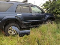
So, I worked like mad to get the rear drawers in place for the camping trip this last weekend. And while it was a great trip, there was one . . . incident.

While going down a hill, a large flat stone rolled over between the passenger side wheels, got caught in the rear running board bracket, and smashed it back and up. It ripped some hardware out of the running board, and pushed the running board up far enough that it popped the trim panel off of the rear door.
IMG_20180505_161200-800.jpg

Fortunately, there doesn't appear to be any significant damage to the body, and there's nothing wrong with the trim panel that some epoxy won't fix. All the little trim clips are busted though. The local dealer wants $5 PER CLIP :twitch: for replacements (I didn't bother to ask about the rivets). Needless to say, THAT is not happening. So I've ordered a pack of new clips and rivets for substantially less of amazon. Should be a pretty easy fix.

The running board is probably toast though. So, time to start figuring out which is my favorite set of sliders . . .
 

Attachments

  • IMG_20180505_161200-800.jpg
    IMG_20180505_161200-800.jpg
    85.9 KB · Views: 428
Well, I was installing a bunch of other electronics, and I came across this little gem: the Anker "SoundSync Drive" Bluetooth Adaptor
A3351011_TD01.jpg


Now that I have the USB ports, right in the console where the AUX in port is located, it's hardly worth calling this a mod - I simply plugged the thing in.

The only real question was where to mount the puck. After some thinking, I ran the wire under the center console and have the puck sitting right on the center divider for the cupholder.
View attachment 248340

A little configuration of my Android phone and we're in business. Here's what I've got going on:

Now, the phone connects whenever I start the car, and plays through the AUX setting on the radio.

There is some alternator whine on the line, which I'm going to have to take care of, but that's a project for another day. (I'm open to suggestions if you have an easy to deal with it!)

So... if a year and a half isn't too late for a response, try using a ferrite core around the audio cable. https://en.wikipedia.org/wiki/Ferrite_bead

That *might* help with the alternator whine.

The "real" fix often has to do with your ground source and ground loops, and running your power wire directly from the battery, but given that this device is powered by a USB cord, I don't see much chance of a "real" fix.

Thanks for your write up. I'm enjoying it. I'm looking at putting a HAM radio in my '08 4R limited. Is your radio a Chinese brand? If so, would you share which brand and model.

Also, I should add that those "add a tap" 3M clip ons sometimes cause problems over time, and can be susceptible to noise.

Crimp terminals with heat shrink can be good, but you have to cut the factory wires for that -- something that many suggest you avoid.

I like wrapping the new wires around the existing wire, soldering and sealing with 3M Electrical tape.

Often using a wire stripper like this .
41RUzi0Vh4L.jpg
can allow you to open a space in the wiring
without cutting it and without too much hassle. Sometimes carefully using a box cutter, you can remove a little more wire coating if necessary. Yes, it takes longer to strip, wrap, solder and tape, but the results usually tend to be more reliable. Over the years I have many intermittent problems problems from those taps. They can become loose where they tap into the main or add-on wire, and this can causes lots of frustration. Occasionally, I've even had the wire eventually break where the tap is installed. -- Just a suggestion.

Thanks!
 
Last edited:
So I got one of these, and it made all the difference!
71WBDdHLrhL._SX425_.jpg

It does seem to attenuate the audio a bit, but the alternater noise is almost completely gone (only noticeable when the volume is WAY up). I think we're good! Thanks for the tip!

(It's amazing how much better the audio from my phone sounds now. $9 well spent!)

Guess I should have finished reading your thread before I responded. :tape: :ohwell:
 
Guess I should have finished reading your thread before I responded. :tape: :ohwell:

It's all good! I didn't even have to break out my trusty Hakko soldering iron! :-)

Anyhow, the radio is indeed a cheap Chinese one: it's an Anytone AT-5888VU. However, many of these small mobile radios use similar mounting hardware. If you have something else in mind, send me a note and we can check some measurements to see if my printed parts will work.
 
It's all good! ... If you have something else in mind, send me a note and we can check some measurements to see if my printed parts will work.

Thanks, McCand!

If/when I get a mobile unit with a removable face, I'll look you up re: getting files to custom print a mounting plate.

Your work is really inspired and you've done an awesome job!

-Phil
 
The End

Well, last week last week Bilbo decided it was time to head to the Havens and sail off into the west.

I was rear-ended, and while the damage was limited to the rear right corner (and my bicycle and bike rack), the insurance adjuster decided that the wound "tis not so deep as a well, nor so wide as a church-door; but 'tis enough, 'twill serve". :rip:

I'm going to leave this post thread active and if others have questions about what I've done, please feel free to reach out. I'm still working on seeing what my next vehicle is going to be.
 

Attachments

  • Bilbo final-K98.jpg
    Bilbo final-K98.jpg
    98.3 KB · Views: 218
Last edited:

Members online

No members online now.

Forum statistics

Threads
278,306
Messages
3,554,045
Members
248,016
Latest member
Advally Service

Trending content

Back
Top