Okki's Build Thread

Replacement Wiper Blades

Replacement Wiper Blades
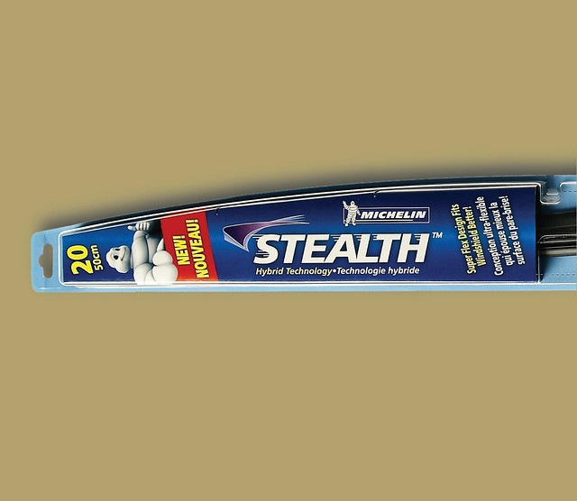
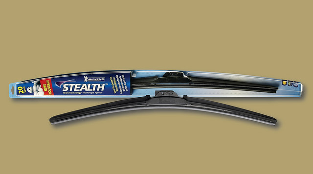
Michelin Stealth $ 25 Walmart

Driver side wiper blade size: 24
Passenger side wiper blade size: 20

THE CHOICE
When the OEM wiper blades got worn out I initially purchased a set of Rainex Latitude wiper blades. I've used them on our R32 and love them for that application. On the 4Runner they look very weird and unfinished in my mind (the plastic mounting point sticks up well beyond the top of the wiper arm).

The next option was the Michelin Stealth.

THE WINNER
8362487715_879fa985e6_z.jpg

8363552582_f084a2e013_z.jpg

They simply snap onto the loop on the end of the wiper arm. It does take a fair bit of force before they snap and lock in, but the instructions in the packaging is pretty clear and straight forward on how to do it.

Installation time, 5 minutes. So far they have worked well in both rain and snow blizzard.

Okki

UPDATE 1/10/2015:
After almost exactly 2 years I'm replacing my wiper blades. The passenger side is not too bad, but the driver side is streaking beyond acceptable levels. Considering we've had 2 harsh winters (1 still in progress) here in Indiana and they have also been baked out west, I've been pretty happy with the performance of these wiper blades.
 
Last edited:
Thanks for sharing, now I know what I'll replace wiper blades with, just need to remember this when time comes.
 
I have tried all the brands mentioned. They all worked quite well, but Bosch has some that I thought were a step above IMHO. I don't remember what I paid for them, but they were a bit on the expensive side as far as wipers go.
 
I have tried all the brands mentioned. They all worked quite well, but Bosch has some that I thought were a step above IMHO. I don't remember what I paid for them, but they were a bit on the expensive side as far as wipers go.

Hi Jay, I think the OEM blades are Bosch. They are about $5 more per blade. I think the Michelins are a good "budget" option. I'll post an update in a few month .
 
Last edited:
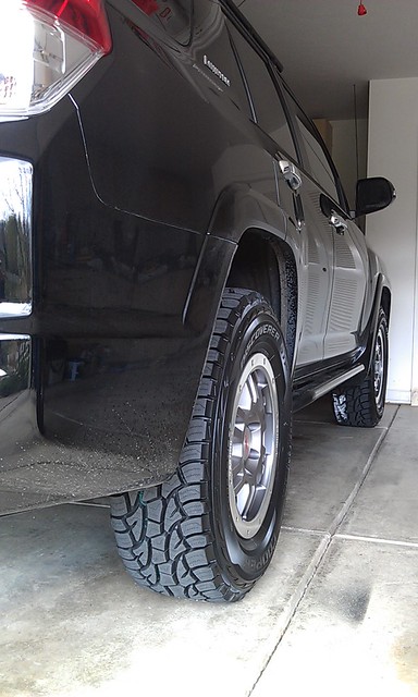
17INCH RIMS & TIRES
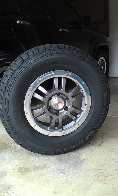
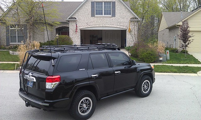
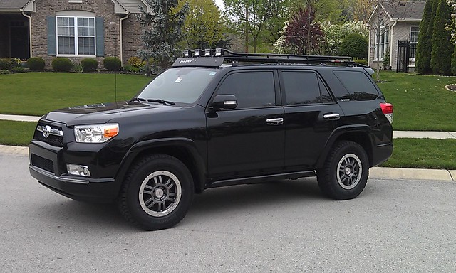
TRD forged 17" rims (PTR45-35010) $1,650.00 5 rims toyotatrdpart.com
Wheel Installation Kit 12mm Conical (PTR27-89100) $150.00 toyotatrdpart.com
Shipping $60.00 toyotatrdpart.com
Cooper Tire Discoverer ATP $1,343.53 Discount Tire
Sold OEM rims and tires $(1,175.00) [Private sale]
Total $2,028.53

Current Pressure: 40PSI
Torque Specs: 82ft/lbs (112N-m) - Do NOT use an Impact Gun. Air ratchets are OK.

Tire Details:
121/118S
Load Range: E
LT265/70 R17

Specs:
1 ply nylon
2 plies steel
2 plies polyester

Sidewall:
2 plies polyester

6865563350_036d7caa5d_z.jpg

7035530599_febccfbefe_z.jpg

6889428748_5388a5fd0d_z.jpg


Okki,
I really dig the TRD wheels. I might have to take a page out of your build :evil:

Do you have any pictures of the wheels/tires from the rear?
 
Replacing The Key Fob Battery

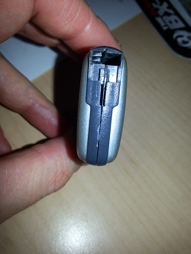
#1. Release Key by pressing down on the release panel on the side (it has a key insignia on the lever)
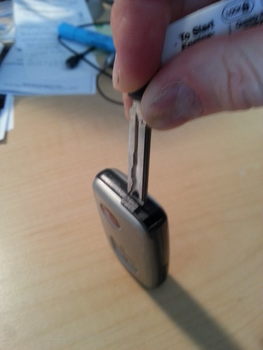
#2. Remove key by pulling chain with release panel open at the same time.
8508653310_3de9861eb4.jpg

#3. Use flat pry tool (the end of the key works great) to separate sides of fob.
8507547599_59110db820.jpg

8507554197_0036bcb96d.jpg

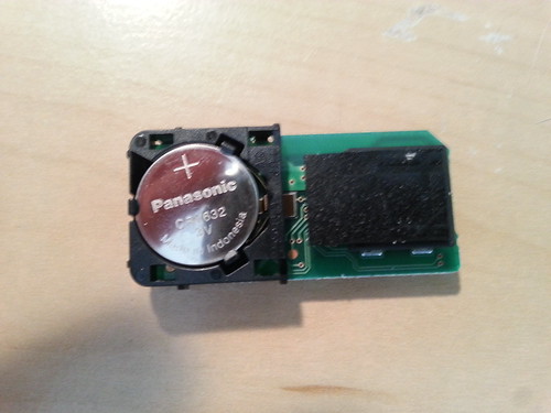
#4. Remove old battery.
#5 Replace with new battery (3V CR1632) in 2010 4Runner LTD.
8508706568_dd5e2baca9.jpg

#6. Snap sides back together.
#7. Reinsert key.
 
Last edited:
Roof Mounted Hi-Lift Extreme 1/3

Hi-Lift w/ Mount
GT4HILT: GOBI Toyota 4Runner Hi-Lift Attachment $ 140.95 EAD Offroad
Highlift base $ 59.50 Off-Road Base (ORB) Amazon
XT485: 48" Hi-Lift Extreme $ 100.94 Hi-Lift
Total $ 301.39

8355106581_187a61a042_z.jpg


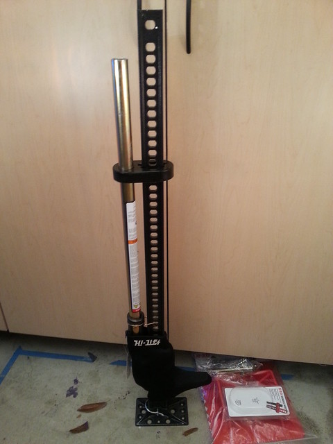
Once you start considering lifting your vehicle,or taking it offroad into situations where you may not have a normal surface under the truck, you’ll quickly discover the need for a Hi-Lift. For precisely that those two reasons I added a Hi-Lift Extreme to my truck. I also added an offroad base and SBE Square adapter to my recovery bag. The video below shows the Hi-Lift jacking up the truck by the slider, using the SBE adapter.
<param name="flashvars" value="intl_lang=en-us&photo_secret=2a0f9e1483&photo_id=8399671627"></param> <param name="movie" value="http://www.flickr.com/apps/video/stewart.swf?v=109786"></param> <param name="bgcolor" value="#000000"></param> <param name="allowFullScreen" value="true"></param><embed type="application/x-shockwave-flash" src="http://www.flickr.com/apps/video/stewart.swf?v=109786" bgcolor="#000000" allowfullscreen="true" flashvars="intl_lang=en-us&photo_secret=2a0f9e1483&photo_id=8399671627" height="300" width="400"></embed>

ACCESSORIES:
SBE Adapter:
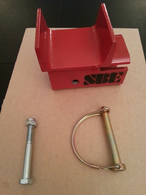
I added the SBE Square adapter to my revocery bag to be used with the Hi-lift. This is a hi-Lift specific accessory that allows the user to get a more secured hold of the vehicle they are lifting. A square (pictured), round and V-shaped adapter are offered by SBE. In all cases, the adapter is slid over the left arm and secured with either a locking pin, or bolt.
8381056349_9d93322bfc_z.jpg


Hi-Lift handle retainer:
I got the Hi-Lift handle retainer to secure the handle and while it does what it needs to do; I will probably switch to the DayStar handle retainer in the near future. The DayStar version is a more minimalistic design and because it’s not a “fits all makes and models” design is a more secure and tightly fitting design.

Hi-Lift neoprene zip cover:
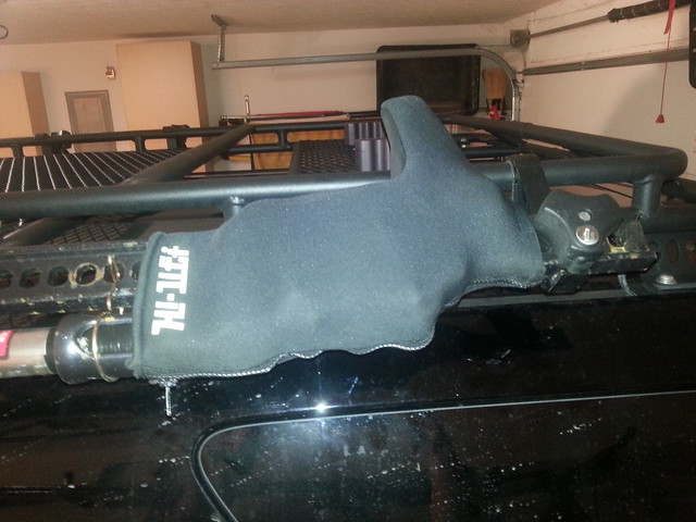
The neoprene cover I got is the small cover that only covers the carrier. There is a larger version that covers the whole Hi-Lift, but it does not appear to allow for the unit to be secured to a roofrack by the holes in the beam. This cover may be more suitable if you are storing the jack inside the vehicle.
 
Last edited:
Roof Mounted Hi-Lift Extreme 2/3

MOUNTING THE HIGH-LIGT TO THE GOBI RACK:
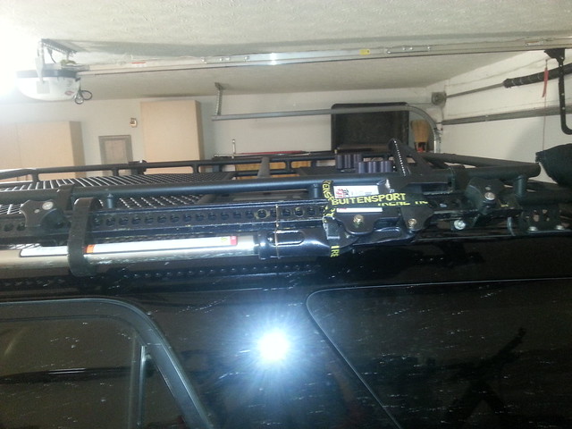
I went through various configurations of mounting the Hi-Lift until I found a manner in which it was suitably secured and minimized noise inside the truck. In order to determine the spacing of the Gobi attachment brackets, I attached them to the Hi-Lift before mounting the entire assembly to the roof rack.

In order to get the best results I attached the first bracket just above the rubber handle retainer. The second bracket I positioned just BELOW the Hi-Lift carrier. In the picture below I still had it above the carrier.
8401281509_8373a143b1_z.jpg


After some trial and error I positioned both the handle retainer and the carrier in between the two brackets and this did two things:
1) The carrier cannot be removed of the main beam.
2) Possibly reduced noise created by the main beam flexing when driving over pot-holes/rough surface.

8565840933_83517c9455_z.jpg

As visible in the image above, I also removed the lift base from the Hi-Lift.

RATTLES AND NOISES:
When I first mounted the Hi-Lift to the Gobi, it sounded like a had a stack of sheetmetal banging around in the back of the truck. There are several things I did to remedy the issue(s).

Noise 1: whistling from the handle.
The driving at higher speeds and with certain relative wind directions, the handle whistles. This is easily fixed by plugging the end with a rubber stopper that can be had from your local hardware store for about $1.-
8505757168_88c75c36e9_z.jpg


Noise 2: carrier and handle rattling on the main beam.
The Hi-Lift is built to be mud covered and elements exposed and still work when you need it. This means that the clearances are large and thus things rattle when jarred as you drive on rought surfaces or hit a pothole. After trying several different ways of tying the carrier down I found the following manner both efficient and easily implementable, regardless of how dirty your Hi-Lift is.

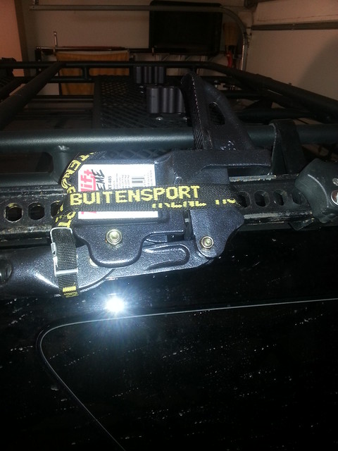
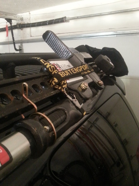
Feed a nylon strap with a clamp on one end (or a figure-8 buckle) through the main beam, just above the carrier. With the length of my strap I was able to loop twice around the carrier. After the second loop I wrapped once around the handle in order to keep it from rattling on the fulcrum pin. I then secured the strap through the clamp and pulled the remainder under the looped sections to keep it out of the way.

Note: you could achieve similar results by using zip-ties, but I wanted something that I could reuse on the trail and zip-ties seemed to be a less desirable option in that case since I would likely have to cut them off to release the carrier and thus bring spare zip-ties to replace them.
8565847589_9f2d73441a_z.jpg


Noise 3: handle-carrier insert.
The handle that inserts into the carrier has a good bit of clearance that allows it to rattle at the top of the insert. Start by pulling the cotter-pin and remove the handle from the carrier. Take note how far it sits into the carrier. Grab some electrical tape and wind the handle with one layer of electrical tape (50% overlapping per wind). Feel for the indentation where the hole is for the cotter-pin and punch through the tape with the tip of a pocket knife or small screwdriver to open it up again.

Next reinsert the handle into the carrier and push the cotter –pin back in place. The handle should fit snugly now within the carrier insert.
8566939462_8426c96bb7_z.jpg


Neoprene cover:
Finally I use a neoprene cover to keep the carrier covered and protected from the elements. This also protects the nylon strap from weather exposure and from flapping in the wind.
8566936508_d4f386ae62_z.jpg


Noise 4: The flat base rattling:
The base of the hi-Lift is attached with only retaining pin. I had some electrical tape wrapped around the bottom of the beam to dampen any movement, but nothing stopped it from rattling. With the base removed and stored in my recovery bag, the noise generated by this part was eliminated.
 
Last edited:
Roof Mounted Hi-Lift Extreme 3/3

FAILED FIXES:
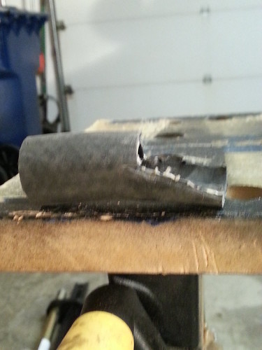
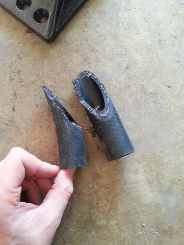
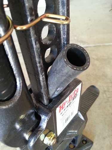
My first thought to keep the carrier from rattling along the beam was to use the clearance between the carrier and the beam and insert some sort of rubber stop to keep the two from making contact. I picked up some 3/8 radiator hose at my local hardware store and cut a stepped section out of it.
8441869209_5e8be176c5.jpg


The next version skipped the step and was simply an angled cut.
8505764176_c12e14feeb.jpg


In both cases I pressed the sections as tight as possible in between the carrier and the beam. Even after compressing the inserts under a weight, they would never fit far enough in between the two parts to properly function. Either they were to thin and the carrier would still contact the beam, or to thick and not fit in far enough to make a difference. Fortunately there wasn’t a lot of money involved in this experiment.
8505762514_c53c07d305.jpg


Okki
 
Last edited:
Great write up on Hi-Lift. I ordered the Extreme not too long ago. i love it - great product. I will now get the rubber plug- good stuff.
I have the handle stop and neoprene cover. I sprayed the inside of cover with WD40 silicone spray (can't hurt).
I have this on order,
GarageMateâ„¢ BajaBusterâ„¢
I am going to give it a try. Found at WalMart.com for $39.00. I figure its worth a try.
Again, great post - thanks!
 
Measuring Suspension Height and Overall Height

When you are planning to upgrade your suspension and/or lift your truck, there are a number of measurements you will want to take before starting work in order to be able to accurately lift your ride, or set your suspension height.

The Basics:
In order to compare apples to apples, make sure you record the following basics when you take your measurements.
- Tire Pressure: This will have an impact on the overall truck height measurement.
- Gas Tank: make sure you are at the same gas level when you take your comparison measurements.
- Vehicle weight: make sure you have the same amount of weight in/on the truck when you take your comparison measurements.

Tools Needed:
- Painters tape
- Tape Measure
- String
- Small weight (nut or bolt)
- Landscaping Level or straight 2x4
- Small ruler

The Process – Suspension Height:
In order to measure the suspension height, you want to measure from the center of the wheel, till the base of the wheel arch.

In order to determine the center of the wheel, take two sections of painters tape and create a cross by going from one spoke to another. Make sure the spokes or recesses are straight across from each other.

Place a section of tape along wheel arch. On this section you will mark the center line to the wheel center.

Next, tie your weight to one end of your string and use some tape to tape the string to the fender. The weight will keep the string tight and straight down. Align the string-line with the center of the wheel as identified by the center of the crossed pieces of tape on the rim.
8586311365_74f8b4902a_z.jpg


Draw a line along the string on the fender tape. Place your tape measure along the center of the rim and align the top with the line on the fender.
8586309945_1f6b566244_z.jpg


The measuring tape will be spaced away from the center of the rim due to the tire. Use a small ruler in order to determine the distance from the bottom of the wheel arch to the center of the wheel by bridging the gap between the measuring tape and the painters tape.
8586297571_5f135ce9ea_z.jpg


Repeat the process at each of the wheels, front and back, passenger and driver side.
8587400558_37c3e08d66_z.jpg


The Process – Overall Height:
When you measure overall height, keep in mind that aside from weight in/on the vehicle, gas level in the tanks, you also have to keep in mind the tire pressure as it affects the overall height of the vehicle. In most cases the difference will not be that much, but it may just be the difference between getting in (or out) of your garage or not.

Find the highest place on your truck (in my case my Hella roof lights). Place the landscape level or 2x4 on top of that point and have it stick out the side of the truck so you can measure the distance from the bottom of the level to the floor.
8586282779_ddbbb8c2ae_z.jpg

Because of the lean of the 4Runner (gas tank on the driver side) I only measured the passenger side since that’s the high side.

The Results:
Variables:
Full tank of gas.
Tire Pressure: [not measured]
Vehicle Weight: No additional weight in truck.

Passenger side:
Front: 19.5”
Rear: 21.5”
Overall: 76”

Driver side:
Front: 19.25”
Rear: 21.25”

8586281221_3db4c35527_z.jpg


UPDATE: Measurements with my Icon Stage 6 suspension are located here

The Analysis:
With the truck measuring at 76” height and the garage opening measuring at 82” (80” if you measure from the bottom of the door beam, to the inside garage floor) from the beam to the driveway, that gives me up to 4 inches of overall play. With 1 inch subtracted for clearance for the garage door, that gives a 2 inch raise in suspension plenty of room and leaves an extra inch in case the tires get inflated to a higher PSI.

Okki
 
Last edited:
The driving at higher speeds and with certain relative wind directions, the handle whistles. This is easily fixed by plugging the end with a rubber stopper that can be had from your local hardware store for about $1

I have to ask where you found this. I was at Home Depot and Lowe's this week for other house projects and wandered around looking for something to shove in my Hi-Lift handle and came up empty handed. The store employees couldn't think of anything either. Any advice is appreciated. Thanks again for the write-ups. I used all your Hi-Lift mount tips with great success!
 
I have to ask where you found this. I was at Home Depot and Lowe's this week for other house projects and wandered around looking for something to shove in my Hi-Lift handle and came up empty handed. The store employees couldn't think of anything either. Any advice is appreciated. Thanks again for the write-ups. I used all your Hi-Lift mount tips with great success!

I picked up my rubber plug at my local Ace Hardware store, but you should be able to find something at Lowes:
Shop The Hillman Group 5-Pack 1-1/4-in Black Rubber Hole Plugs at Lowes.com

Hopefully that links helps. If you check the drawers in the hardware isle (nuts bolts, washers etc) they usually have a few drawers with odds and ends like the rubber plugs.

Okki
 
Rear Air chuck and Pressure Gauge 1/4

Air Chuck in Truck Rear
Air Pro PUR-14X050 1/4-inch by 50 Polyurethane 250 PSI Air Hose $ 26.32 Amazon.com
Parker CPI 6-4 CBZ-B Brass Compression Tube Fitting, 90 Degree Elbow, 3/8" Tube OD x 1/4" NPT Male $ 10.01 Amazon.com
Parker A-Lok 6ET6-B Brass Compression Tube Fitting, Tee, 3/8" Tube OD $ 16.05 Amazon.com
Anderson Metals Brass Tube Fitting, Elbow, 3/8" Compression x 1/8" Female Pipe $ 7.02 Amazon.com
Viair 90080 Gauge $ 35.95 Amazon.com
Ampro A2570 5 Piece Air Coupler Set Brass, Milton Type $ 7.52 Amazon.com
Small_Compressor_Facep late.fpd - Thickness: 2.5 mm $ 37.26 Front Panel Express
Total $ 140.13

COMPRESSION FITTINGS 101

One of the main issues I ran into with this project was using compression fittings. I thought I understood how to use them, but ended up having blowouts every time I pressurized the system. Eventually I figured out what I was doing wrong and things are working like a charm now.

My mistake was having the sleeve right at the end of the hose. Instead the hose should fit all the way into the female fitting, with the sleeve right at the end of the female fitting. The nut that goes over the sleeve should be hand tightened and then turned another ¼ turn. It should NOT be tightened and further.

You should also never use Teflon tape with compression fittings.

  1. Make sure you have a clean edge on your hose.
  2. Slide the nut over the hose.
  3. Slide the compressing ring/sleeve over the hose (spray the hose with some WD40 to slide the ring a little easier).
  4. Insert the end of the hose into the female fitting and check the depth.
  5. Move the compression ring/sleeve so the sleeve fits snug with the female fitting while the hose is as deep as possible seated in the female fitting.
  6. Tighten the nut till hand tight.
  7. Tighten the nut another ¼ turn.

8860617457_47509000e1_z.jpg
 
Last edited:
Rear Air chuck and Pressure Gauge 2/4

FRONT PANEL
I used Front Panel Designer to have the face plate manufactured. You can download the software for free at:
Front Panel Express:*Customize Your Front Panel and Enclosure Design

The faceplate file I used is attached to this post.

I positioned the faceplate and used some duct tape to hold it in place.You will have to make sure to mount the face plate as low as possible on the wheel arch in order to minimize the interference of a reinforcement rib on the back of the wheel arch plastic.
8711419577_38ce40b80e_z.jpg


Once you have the face plate properly positioned, I used a spade bit in order to drill the hole for the air chuck.
8712544276_c38d3c3190_z.jpg


I used a rotary bit (from my Dremmel) to cut out the face for the pressure gauge. I used a round rat tail file to clean up the edges and have the gauge fit nice and snug. Notice that there is a small notch at the bottom that aligns with a bump on the gauge.
8712539354_f1b0e15154_z.jpg


With the faceplate, gauge and chuck mounted (I used some small screws/nuts on the 4 corners) you are ready to focus on the air line.
8712537460_f819790210_z.jpg
 

Attachments

Last edited:
Rear Air chuck and Pressure Gauge 3/4

RUNNING THE AIR LINE
Starting at the pressure gauge, I used a T to tie the chuck and gauge into the main line.
8860620199_fd5b1ac73e_z.jpg

I did end up adding a hose clip around the barb side of the chuck in order to prevent it blowing off there.

After several tries of keeping the line segments as short as possible, I realized there is more then enough room and I added a longer section between the gauge and the T and that solved a lot of my routing issues.
8917691682_3e94c465b0_z.jpg


With the 3/8 outer diameter of the air hose, finding a route from the rear to the front was a bit of a challenge.

Once an exit point was located to get the hose out of the inside of the cab and under the truck, things became a little easier. I tried to run the hose inside the normal opening of the large grommet, but ended up cutting a hole in it. Once you have a length of hose fed into the truck, you can reach in through the wheel arch and grab the end (smaller hands help).
8784815877_57186848d1_z.jpg

8795390602_87534fe5f6_z.jpg


Once under the truck I used long zip-ties to secure the air line along the frame and around the spare tire.
8861285412_e8ca060a35_z.jpg


It’s a tight fit around the rear coil spring, but there is enough room to run the airline (I also have my breather relocation line joining here). Once around the rear suspension, the airline will follow the frame rail along with the breather relocation line that I did in an earlier mod.

The images below show how the airline stay out of the way of the suspension, using other factory hoses and wire bundles as guides.
8860668843_f841187048_z.jpg

8861289060_af7efca6de_z.jpg

8860664957_5cbe72ea68_z.jpg


Once the rear suspension is cleared, the airline simply follows the frame rail as close to the top as possible. I was able to reuse the zip-ties from when I ran the breather relocation. Make sure that the zipties keep the lines in place, but are not so tight that they restrict/compress the hoses.
8861270552_def08c6e9c_z.jpg


The image below shows the breather line and compressor air line as well as the adjusted path for the XREAS line in order to clear the gusset of the Shrockworks slider.
8860658375_c2bc5a6e83_z.jpg


Once at the front wheel well, the air line squeezes behind a body mount and through the back corner of the wheel well and up into the engine bay. Again I’m following the route of a factory line (in this case the XREAS line).
8861263342_b2bfcec5f1_z.jpg


Looking inside the driver front wheel well, you can see where the air line come from the frame and curves up into the engine bay along the fire wall.
8861258790_514b424d68_z.jpg


Looking down into the engine bay along the fire wall on the driver side, you can see the hose and reach in to pull it up to the top or the fire wall.
8860646281_371877abc5_z.jpg


Inside the engine bay, I routed the air line along the bottom of the windshield (following the cable bundles that’s already there) to the passenger side and then around the compressor (passenger side fender) and back towards the center of the engine bay and connected up to the compressor.

A secondary benefit of running the air line from the driver to the passenger side was pointed out by [MENTION=78705]jangoforhire[/MENTION] in that it leaves enough hose to run it to the front of the car in case you want to add a 1 gallon air tank behind the bumper on the driver side.
8861246392_9886540f59_z.jpg
 
Last edited:
Rear Air chuck and Pressure Gauge 4/4

LIGHTING UP THE PRESSURE GAUGE
(To be added in the next couple weeks)
 
Last edited:

Members online

Forum statistics

Threads
278,307
Messages
3,554,056
Members
248,016
Latest member
Advally Service

Trending content

Back
Top