Okki's Build Thread

REMOVAL OF THE LIMITED ROOF BARS

A 12mm socket wrench will remove the bolts.
5988945761_6f24fd7704_z.jpg

Who makes these sockets with the large easy to read sizes. I need'em.
 
Big 3 Upgrade

In preparation for my DC Engineering XP270 high output alternator, I completed the "Big 3 Upgrade". This basically means ADDING:
- a second positive from the alternator to the battery,
- a second ground from the battery to a (body) ground,
- a ground from the engine to a (body) ground.

For the technical details of the big 3 upgrade, please see [MENTION=83083]rigtec[/MENTION] 's very detailed post here: http://www.toyota-4runner.org/2449367-post1.html

I Used:
2 AWG Premium Extra Flexible Welding Cable 600 VOLT COMBO PACK - BLACK+RED - 15 FEET OF EACH COLOR - EWCS Spec - Made in the USA!
https://www.amazon.com/gp/product/B0167K786A/ref=oh_aui_detailpage_o03_s00?ie=UTF8&psc=1

Install Bay Copper Ring Terminal 2 Gauge 3/8 Inch 10 Pack - CUR238
https://www.amazon.com/gp/product/B005V9UWB2/ref=oh_aui_detailpage_o03_s00?ie=UTF8&psc=1

Make sure you get heat shrink and loom if you don't have any in stock.

I used the following crimper:
10 Ton Hydraulic Wire Battery Cable Lug Terminal Crimper Crimping Tool 9 Dies
https://www.amazon.com/Hydraulic-Ba...=1471914923&sr=8-3&keywords=hydraulic+crimper

The tools/Parts needed:
29119718385_951d3691b5_z.jpg


Trim your cable to length:
29119718735_5750f77d11_z.jpg


Strip to the proper length for your lugs:
29119720355_0339e853d3_z.jpg


Crimp on the lugs with a good, solid crimp:
29119713475_ec851a55f1_z.jpg


Get all your lengths done:
29119708635_a7bd8137d1_c.jpg


Trim the alternator pin protector to allow the addition of your "big 3" positive cable.
29042702301_73e3a48ae6_z.jpg


Install your secondary positive cable and make sure to add some loom to protect it from the exhaust shield that's close by. Consider using some heat reflective tape as well (see the wire loom behind the red positive).
29119721115_79e874ea4f_z.jpg


Connect to the positive terminal on your battery:
29086865106_5e5f5b23de_b.jpg


Here's how I ran my engine ground. You can see where on the fender I ended up making my second ground connection.
28500731293_8dc98441b1_b.jpg


The secondary battery ground I ran along the fender:
29119722535_6d6df9ac36_b.jpg


Now I'm all ready for when my new alternator shows up!
Okki
 
Last edited:
Rotopax Water Spigot

Rotopax Camp Water Spigot
28836403163_6d35a3e347.jpg


Under $7 for a camp spigot on my rotopax water storage:
  • Spigot at Idaho Wal-Mart $1.80,
  • Threaded coupling at Lowes $0.63,
    LASCO 3/4-in Dia PVC Sch 40 Coupling: Item # 24157 Model # 430007RMC
  • Nylon washer and neoprene washer $3.60 at Ace Hardware.

You do need a spare locking collar for the Rotopax, because you have to assemble the spigot through the opening. Neither washer or spigot fits otherwise through the collar hole.

The Nylon washer from Ace Hardware.
29554622276_47c1cb886f.jpg

Either get a neoprene washer with the same exterior dimension and trim the inside (freeze the washer first) or get a neoprene washer the same size as the nylon (preferred option). I got 2 of each in order to make the collar tall enough so you can tighten it down properly onto the rotopax container. Single, thicker, washers would be preferred, but they didn't have them at my local Ace Hardware and Lowes.

You have to trim the hex collar of the female union. You are left with a smooth, threaded section of pipe that will lock the nylon washer and neoprene washer to the spigot. Make sure you get a thicker set of washers. the stack needs to be about 1/4 inch thick in order to be able to be tightly locked by the Rotopax locking collar.

29402600641_1855dcfddb.jpg

28834039784_c399898845.jpg

29458165425_6f52c5d99e.jpg

29169765520_58194d54b6.jpg

29458169365_ba3ecae6fd.jpg


Enjoy your easy access to water at base-camp!

Okki
 
Last edited:
Roof Power along the A-Pillar

It's been brought up a number of times, but there seem to have been very few pictures on the subject, so here are a few.

My roof power was having some issues (more on that later) so I ran a temporary power and ground line from the driver side roof down into the engine bay.

This is a bit of an [MENTION=65614]Antman[/MENTION] picture, but you can see the wire coming out of the rain gutter and turning left towards the OPT7 lightbar plug. (The Deutsch connector you see is for the permanent power solution that failed).
28651003943_20293fa62b.jpg


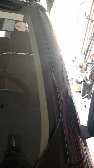
I used the fully loomed wiring that came with the OPT7 lightbar and cut a section to length to use for this project. The rubberized loom they use blends seamlessly with the window trim channel. Just slowly work the wire into the channel. Do not to pull the trim out and away from the windshield. There is no need and that may actually allow water into the A-Pillar when you exit at the top at the roof rain channel with your wire.
29237802656_b2bc68efa3_z.jpg


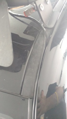
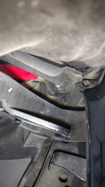
At the base of the windshield, pop out the corner trim piece. There are two clips on the engine side, and on the fender side there is a protrusion that needs to slide out of a hole. You can now run your wire into the engine bay and hook it up to your power and ground.
29272074325_f21d741e06_z.jpg


Hopefully this helps. Let me know if more pictures are needed.

Okki
 
Core Support/Bash Plate

After installing the CBI bumper on my truck, the RCI bash-plate that filled the gap between the OEM bumper and the Shrockworks Skids was no longer needed.

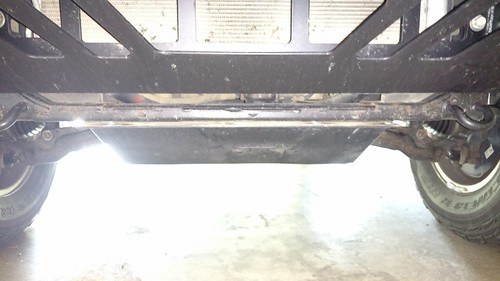
However, the bottom radiator core support was in plain view and subject to more water/snow/mud/etc. So I wanted to add some protection and clean up the look.
28785898092_7d91e375f4.jpg


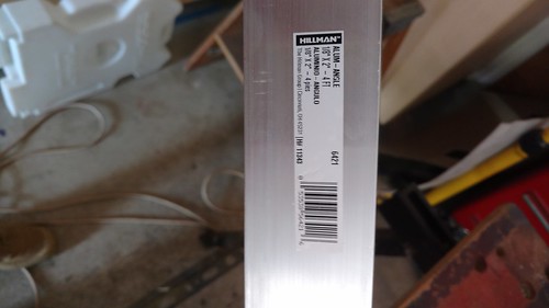
For about $21 at my local Lowes I picked up some Aluminum angle of 1/8" x 2" x 4ft.
28273018004_073c4da145.jpg


I measured to size and trimmed the angle at 28 inches. I loosened the Shrockworks skid plate and used a Sharpy to mark the bolt holes. Keep in mind not all holes are the same size; there are 2 different sizes!
28859423046_ee69937e31.jpg

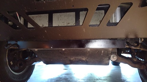
A couple coats of primer and black paint to match the body color and voila!

28605759410_6eb0650ff8.jpg

The finished piece fits like a glove and looks much nicer.
 
Last edited:
Alignment Explained

Since I had some questions about suspension geometry myself, I did some digging and video viewing. Time to get schooled :thumb:

Steering Axis Inclination - Explained
https://www.youtube.com/watch?v=IUcZ63unEyU

Camber - Explained
https://www.youtube.com/watch?annot...&feature=iv&src_vid=Gh7gWJAvOvs&v=jSFmUmVWBp0

Toe-in and Toe-out - Explained
https://www.youtube.com/watch?annot...&feature=iv&src_vid=IUcZ63unEyU&v=83_GTZeuF6M

Caster - Explained
https://www.youtube.com/watch?v=Gh7gWJAvOvs

And if you like it all summarized in a nice Indian-British accent:
Steering Geometry - Camber , Caster , King pin inclination , toe in , toe out
https://www.youtube.com/watch?v=e8GyZReUdQw
 
Where did you run the ground wire into? I'm pretty new to the electrical part of car mods. I see the part attached to the frae but where does the other end wire into? Thanks
 
Where did you run the ground wire into? I'm pretty new to the electrical part of car mods. I see the part attached to the frae but where does the other end wire into? Thanks

The roof lights are powered by an auxiliary fuse panel. I can get power and ground from there. You can also use an inline fuse for the power line and connect to the battery.

Ground can either go straight to the battery negative terminal, or to the ground point on the driver side fender.

Hopefully this helps.
Okki
 
Last edited:
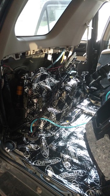
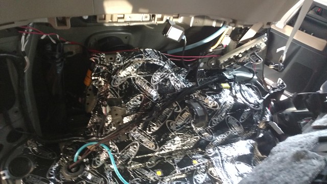
Order placed for a Goose Gear floor! Now to order some Dynamat as well and I've got a Xmas holiday project! :banana::clap2:

Okki
 
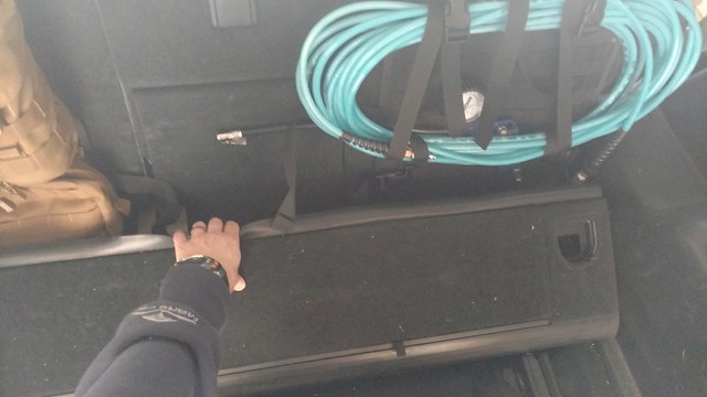
Your build thread is an inspiration. I just ran an air line to the rear compartment of my 4th gen based on your posts. I haven't got the nice pressure gauge and chuck yet (just a loose air fitting) but it'll happen one of these days. Thanks for putting this all out there.
 
Hoping to have full write up in this thread before the weekend is over :ballchain:
Okki

I tried to find this info online and in this forum, but is the goose gear plate birch wood covered in Line-X? or is it made of some other material?

Thanks! Hoping to address my cargo issues soon!
 
I tried to find this info online and in this forum, but is the goose gear plate birch wood covered in Line-X? or is it made of some other material?

Thanks! Hoping to address my cargo issues soon!

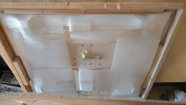
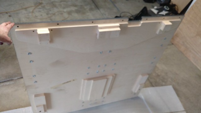
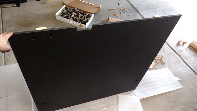
Not sure on the specific wood species, but it looks like birch. I've got pics of the front and back of the unit before it got installed. It's a very nice product.

The top and sides are coated with a line-X type product.

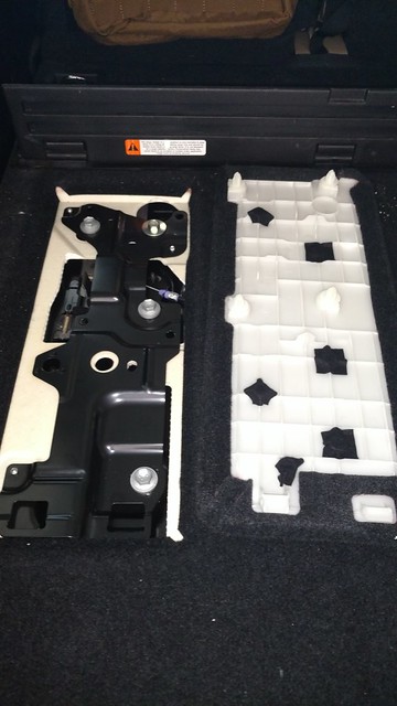
Only question I had about it is why they didn't use the thick bolts in the back like they did at the front of the unit (it uses 4 smaller ones instead), but I'm very happy with the product and the finished installation.

Thanks and have a great day!
Okki
 
Last edited:
Sliding Tray Removal, Dynamat Installation, Goose Gear Floor 1/3

Dynamat and Good Gear Floor Installation (Sliding Tray Removal)

Goose Gear Floor: $520
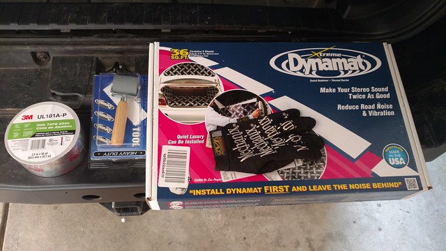
BLACK 10455 - Dynamat Xtreme 36ft Bulk Pack: $163

Tools:
Metric 10 socket (long)
Metric 12 socket (long and short)
Metric 14 socket (long and short)
Hex screwdriver
Trim Removal Tools
Scissors
Dynamat Roller

SLIDING TRAY REMOVAL:
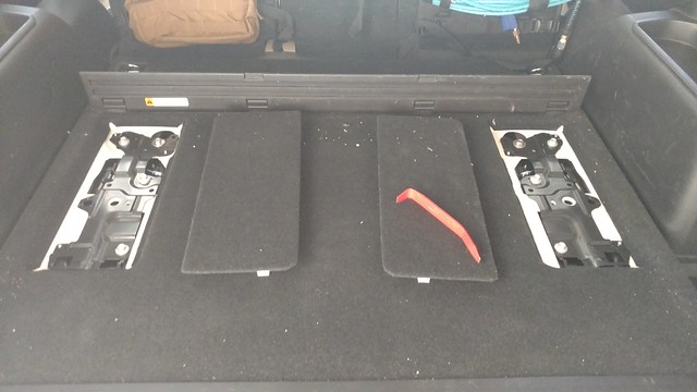
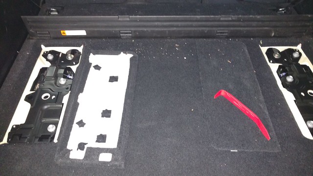
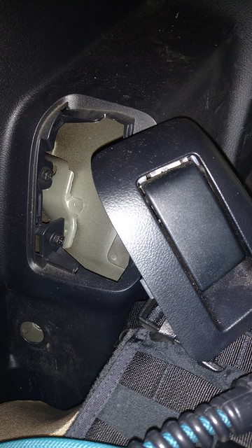
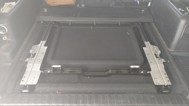
The sliding tray removes fairly quick and easily. First remove the 2 cover panels with a trim removal tool. There is a clip on one side and it hooks into the tray on the other side.
32405255401_2053d05dfe_z.jpg

32527666985_ed0dcff86d_z.jpg


With the panes off, you can now remove the 4 bolts that hold the deck to the sliding assembly.
31684023434_4c1030d856_z.jpg


With the deck out of the way you can slide the guides towards the back in order to gain access to the bolts that secure the track to the body.
32405253801_836e004110_z.jpg


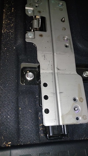
There are 2 bolts; one on either side of the track.
31684021824_cd4e2070a2_z.jpg


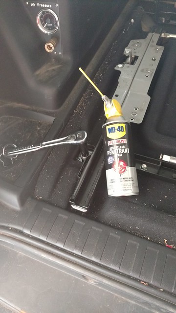
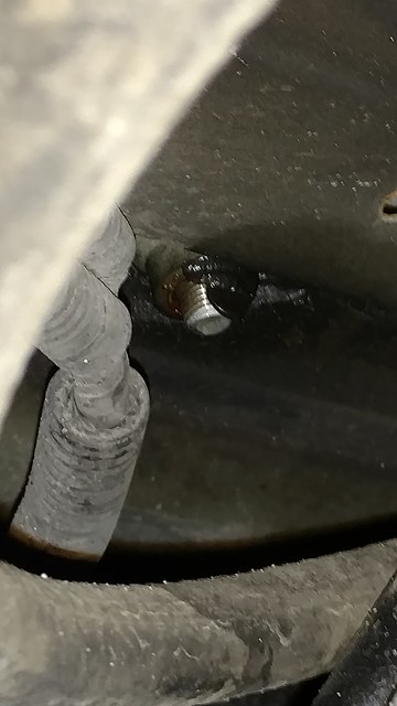
These bolts actually extend through the body and the bottom end is exposed to the outside and thus likely rusted. I sprayed some WD40 Blue Torch to help things loosen up.
31684017204_659bf96e9f_z.jpg


The bolts at the back of the track are harder to get to unless you remove the “hidden storage”. Since it has to come out anyway, this is as good a time as any to do so.

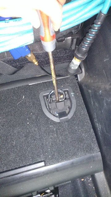
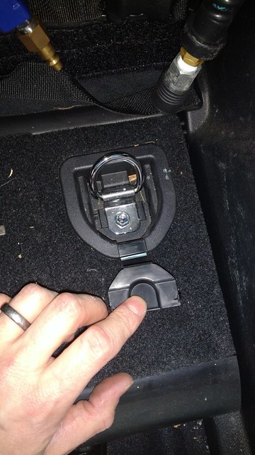
Use a screwdriver to pop open the cover that hides the bolt that secures the D-ring (and the whole storage unit) to the brackets that are found underneath the storage unit.
31684020424_8e6b6964e5_z.jpg


Use a Metric 10 socket to remove the D-Ring bolt. It doesn’t actually come out, but you can tell when it is not longer holding things in place. Pop the whole plastic piece with the D-Ring out. Do this on both the passenger and driver side.
31684019554_9ec5fd1170_z.jpg


Grab the back end of the hidden storage and pull up and towards the lift gate. The whole unit will come out.
32148785470_cf32815b65_z.jpg


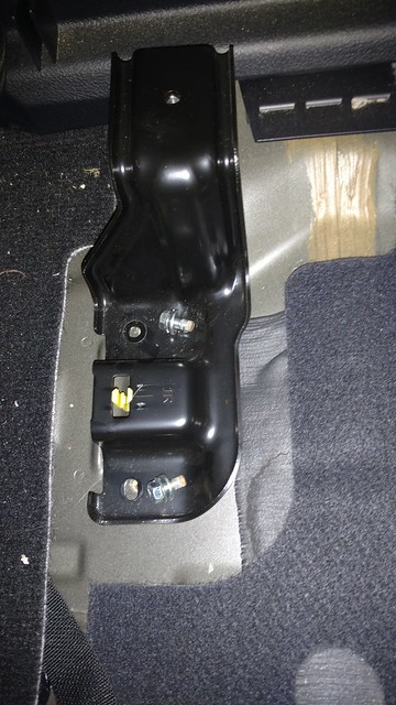
Remove the 2 bolts in each bracket and remove the brackets from the vehicle.
31684015454_7283092048_z.jpg


At this point you should be able to remove the remaining bolts that secure the sliding track to the body and pull the whole track-unit out in one piece.

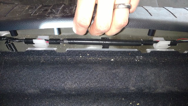
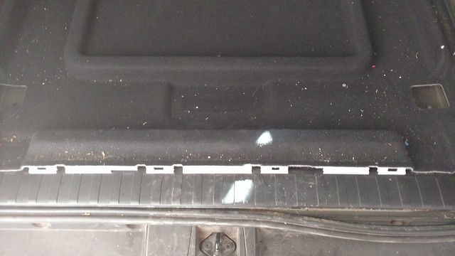
Before you remove the carpet, pull up the trim along the bottom edge of the hatch. It pulls straight up. Just take it easy not to kill too many of the clips. The carpet has clips on the edge, and if you don’t remove the trim, you’ll simply have a harder time getting the carpet out.
32375094082_6b9cef6a16_z.jpg

32375092272_9965cbccb1_z.jpg
 
Last edited:
Sliding Tray Removal, Dynamat Installation, Goose Gear Floor 2/3

INSTALLING DYNAMAT:
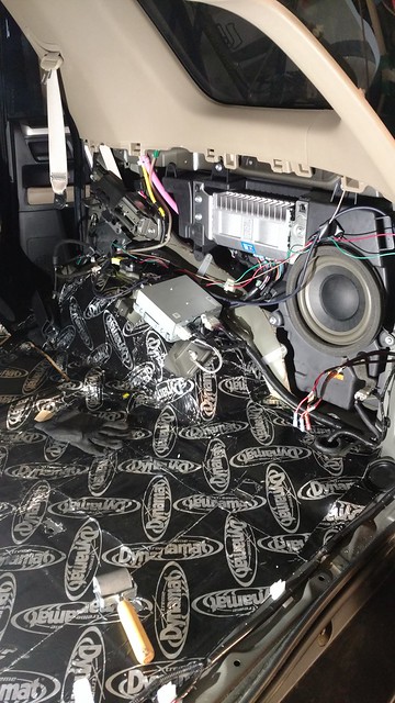
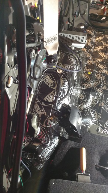
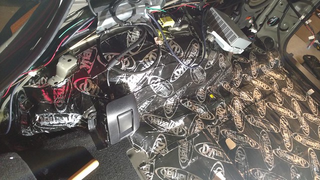
I bought the little Dynamat Roller tool. It’s not the cheapest one, but I got my money’s worth out of it using both the roller, and the back of the handle to push the Dynamat into place. I also use a thick/flat trim removal tool for some of the harder to reach spots. I bought a role of seam tape, but saw no reason to use it. It’s still in the original packaging on my work bench.
31684012784_7a51a4d715_z.jpg


Removing the bottom trim is fairly easy, with the exception of the seat backs. I used the post from [MENTION=113429]RysiuM[/MENTION] here:
http://www.toyota-4runner.org/5th-g...c-cover-over-left-rear-wheel.html#post2521407

The seatback angle adjuster panel comes off by “sliding” it off towards the inside of the vehicle. There are 2 Philips-head screws behind it.
31715710143_022d12cf2f_z.jpg


Remove the 2 screws and keep an eye on the “adjuster”. You’ll need to feed it through the hole as you remove the panel.
31715710143_022d12cf2f_z.jpg


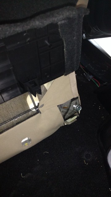
The seatbacks remove by removing a bolt at the inboard side of the seat (Pay attention that you don’t remove the center seatbelt bracket; you don’t need to in order to remove the seatback.). On the outboard side, there is a bolt under the seatback carpet. Give a good tug on the edge of the carpet and it will pop off (it’s hinged about 8 inches up). Remove the corner bolt that holds the seatback to the body mounted rotating bracket.
31684009974_b8877974de_z.jpg


There is an annoying metal “hook” that interlocks the seat back and the bracket. It takes some fiddling, but you can angle and pull away the whole seatback at this time.

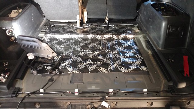
I had started installing the Dynamat before removing the side trim. I disconnected the lead to the sensor in the center of the cargo area so I wouldn’t damage it by stepping on it constantly. (in this image you can see the left side of the 60 split having been released. You can also see the trim removal tool I used as part of the Dynamat install.)
31715714293_5aa808a531_z.jpg


Passenger side wheel well covered in Dynamat (this turned out to be the “easy” side).
31684008674_6cafa3804c_z.jpg


All the way down to the sill plate. That way I don’t have to remove the rear trim when I finish up putting Dynamat in the passenger compartment.
31715704443_3f7b283f76_z.jpg


And passenger side done.
31684007364_5bb83f14f6_z.jpg


The bottom trim removal for the driver side is the same as the passenger side. When all removed it looks something like this.
31715699023_dd08e2ace9_z.jpg


Aaaaaaaand covered in Dynamat. I used a small pair of scissors with a pointy blade to cut the Dynamat. I was also able to use it to cut out some small sections where I realized I had covered mounting holes that needed to be reused. I also saved all the “trimmings” in order to fill in little gaps and awkward spaces.
31684005414_63bcaa6d13_z.jpg

31715705923_145573c31c_z.jpg


With all the Dynamat in place, the Goose Gear floor could be installed. The Dynamat work took me about 3~4 hours on 2 days (about 8 total).
 
Sliding Tray Removal, Dynamat Installation, Goose Gear Floor 3/3

GOOSE GEAR FLOOR:
Brian and the crew were very helpful on the phone and worked with me to schedule my delivery when I actually was in town (we delayed it). They also did an amazing job at packaging and crating this thing up. The crate was damaged (looked like a forklift punched it), but everything on the inside was in great shape with not a scratch on it. Goose Gear was aware of the shipping damage and had already committed to taking care of things if there was damage, so more kudos there (even though it turned out not to be needed).
32527656695_1b521a8848_z.jpg


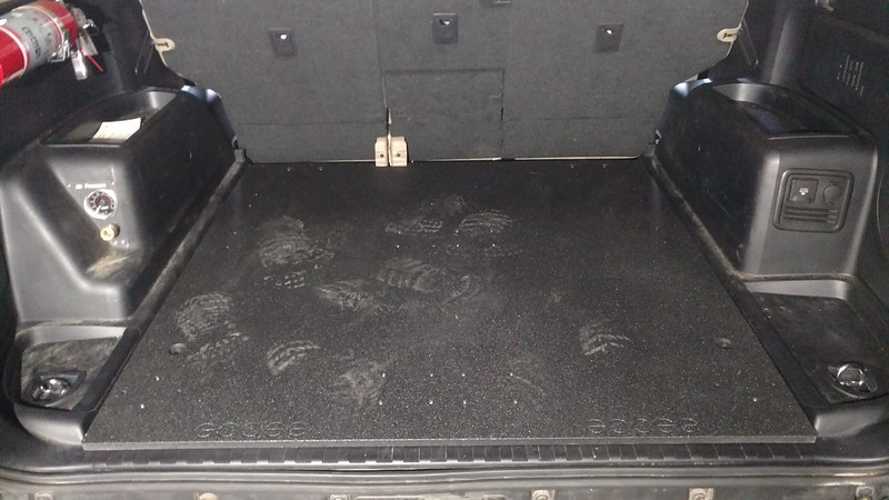
The craftsmanship on the floor is very nice.
31715694343_800e3c84d4_z.jpg

32527644235_0736b5ac90_z.jpg


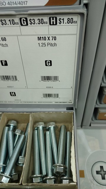
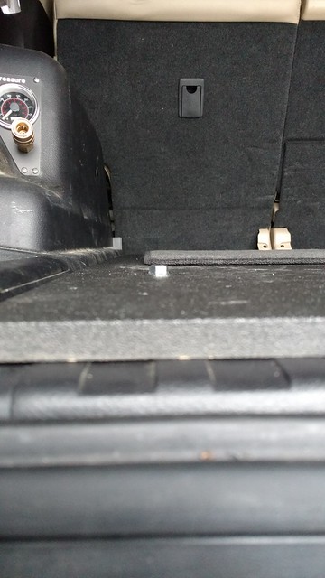
I did provide feedback to Goose Gear that some instructions (and all required hardware) would have been nice. Brian said that it was a hot contested topic around the shop, but the advice to reuse the bolts from the slide is useless. Those bolts are about 3x to short. The notched side goes towards the seat backs.

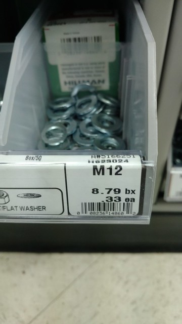
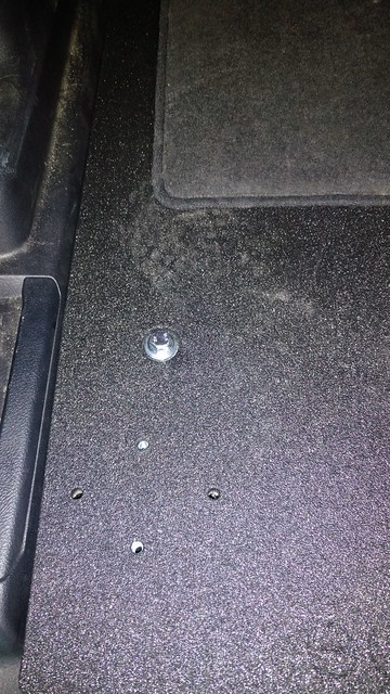
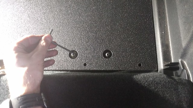
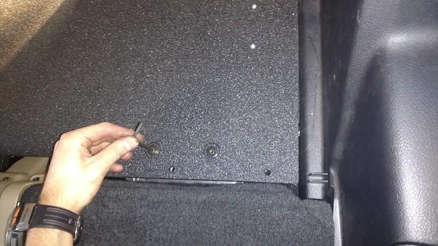
The missing hardware is the 2 large bolts that hold the floor in place towards the hatch. I got what you see below, but will say that it sticks out above the floor surface at the moment. Not sure if that becomes an issue when my fridge slide shows up, but if so I’ll deal with it at that time.
31750195064_526a253763_z.jpg

32441132692_a5ce2ba5da_z.jpg


Align the holes for the main bolts and get the threads started. These bolts will be exposed on the underside of the body. Use some thread compound on these bolts.
32476369291_acf64f971b_z.jpg

32446265182_21d824ae17_z.jpg

32476366851_3c341f0fd3_z.jpg


The bag with included hex-head bolts is for the rear of the deck. There are 2 bolts that will be used on each side (driver/passenger).
32527642165_20db784336_z.jpg

31715687133_4a73e68913_z.jpg


Snug everything up and you are DONE!
31715676643_9a38907728_c.jpg


I’m very happy with the final product in that it gives me a very secure platform on which to mount my fridge and it also give me more usable height in the cargo area AND depth.

I’ll likely reuse the D-Rings from the hidden storage compartment to provide some tie-down points in the back, to use with my spider net.

Okki

Edit: [MENTION=124732]LawnDart[/MENTION], Do the bolts near the hatch on your install stick out above the floor? What did you end up using?
 
Last edited:

Members online

Forum statistics

Threads
278,309
Messages
3,554,068
Members
248,016
Latest member
Advally Service

Trending content

Back
Top