
You are using an out of date browser. It may not display this or other websites correctly.
You should upgrade or use an alternative browser.
You should upgrade or use an alternative browser.
Overland Equipped or PowerTray fuse block plate
- Thread starter mscot
- Start date

WanderlostOverland
New member
The video is uploading right now, should be able to watch it in about an hour. The mount is from Power Trays. They haven't got the photo of the Bussmann Box cut-out up yet but they do offer it.[MENTION=172861]WanderlostOverland[/MENTION] I've been waiting for your video. Which tray is that? I don't see the shape on their site.
WanderlostOverland
New member
Good Eye! With it we can adjust the output anywhere between 7.5 to 35 amps! It's a feature you'll only find on the higher end components.What is this component in blue?
Is that some sort of potentiometer used for voltage adjustment? Like those guys making fuses based on a diode to trick the system to throw out more charge voltage for AGMs?


Bumbo
New member
Good Eye! With it we can adjust the output anywhere between 7.5 to 35 amps! It's a feature you'll only find on the higher end components.
Interesting... Do you have any more information on how this is wired into the vehicle?
I know the diode modification basically uses the forward voltage drop to boost the voltage up a fixed amount.
Most potentiometers are variable resistance, are you using this to adjust the sense voltage which in turn changes the alternator output?
My question/concern more or less revolves around “over-volting” the electrical system since the feedback loop is showing a voltage that is too low?
WanderlostOverland
New member
Interesting... Do you have any more information on how this is wired into the vehicle?
I know the diode modification basically uses the forward voltage drop to boost the voltage up a fixed amount.
Most potentiometers are variable resistance, are you using this to adjust the sense voltage which in turn changes the alternator output?
My question/concern more or less revolves around “over-volting” the electrical system since the feedback loop is showing a voltage that is too low?
I'm sorry, I thought you were just kidding. It's actually just a screw that holds the cover on.
Bumbo
New member
I'm sorry, I thought you were just kidding. It's actually just a screw that holds the cover on.
hahahaha
Perhaps its too late in the work day for me to sense sarcasm.
Well you really had me going with your last comment... looks a lot like a potentiometer I use to to control circuit resistance.


PupuleUlua
New member
Here's what we recently came up with using the Power Trays base platform.
It's much less complicated than it looks.
We'll have a video of the build process uploaded to our Youtube channel very soon, maybe even tonight.

Looking good. Clean install
I can't wait for my powertray. Unfortunately they are out of sPod versions till mid Feb but I can wait
WanderlostOverland
New member
Here's what we recently came up with using the Power Trays base platform.
It's much less complicated than it looks.
We'll have a video of the build process uploaded to our Youtube channel very soon, maybe even tonight.
The video is uploaded to our Youtube Channel!

stphnman20
Member
The video is uploaded to our Youtube Channel!
Just watched it! Thank you for the video. Going to do this myself. How much was the total for this project?
WanderlostOverland
New member
Just watched it! Thank you for the video. Going to do this myself. How much was the total for this project?
Thanks for watching! The total was around $250.
WanderlostOverland
New member
This is a quote from where we gained our info on assembling the Bussmann box. We provide a link to his DIY website in the video description on Youtube;[MENTION=172861]WanderlostOverland[/MENTION]
I watched the video... I noticed you decided to solder the terminals on the Bussman box.
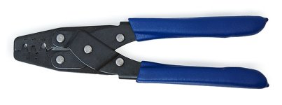
Do you know which crimp tool is recommended for those who prefer a crimped connection?
"In order to crimp Metri-Pack and Weather-Pack terminals, you’ll need a special crimper. The T-18 crimper is a low-cost tool that allows you to crimp 24-14 AWG wire as well as Weather-Pack, Metri-Pack 150 and Metri-Pack 280 cable seals. This tool can be purchased from Amazon or Del City."
Although this special tool will work better, we saved money by simply crimping our terminals with needle-nose, like shown in the video. You likely also noticed that, in addition to soldering our terminals that were installed into our box, we also crimped them.
Attachments
Bumbo
New member
Thanks... I didn't realize its the same connector as the GM / Delphi stuff. I actually have a crimper for that already.
I really like soldering, I have a professional soldering station, a couple of them actually, but for automotive application I much prefer crimping...
Without turning this thread into a soldering vs crimp debate, there are some cons surrounding soldering in automotive or vibration applications.
A proper crimp is also mechanically very strong when done right, I can't pull apart my crimps without tearing the wire from the connector.
Thanks for the video series... it's a lot of work producing content. I've tried and was unable to keep up with the editing.
I really like soldering, I have a professional soldering station, a couple of them actually, but for automotive application I much prefer crimping...
Without turning this thread into a soldering vs crimp debate, there are some cons surrounding soldering in automotive or vibration applications.
A proper crimp is also mechanically very strong when done right, I can't pull apart my crimps without tearing the wire from the connector.
Thanks for the video series... it's a lot of work producing content. I've tried and was unable to keep up with the editing.
Similar threads

- Replies
- 5
- Views
- 5K


- Replies
- 0
- Views
- 3K

