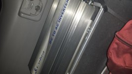
Power Inverter Install

no, the body is a great ground and will work fine. I used the seat bolt for mine.

The other smaller ground is for the inverter case since the main ground is only grounding the internal circuits. Just connect it to the main grounding on the inverter.


really depends on what you running I run 2 awg for my 1000w and I just have to start the car for higher draws to keep the volts up.


Im a fan of Xantrex and would recommend the 1000w model so You can run some higher loads if needed. ive run my little coffee machine(600w) a handful of times.

http://www.amazon.com/Xantrex-806-1...e=UTF8&qid=1426557092&sr=1-1&keywords=xantrex

or the 600w model

http://www.amazon.com/Xantrex-806-1...e=UTF8&qid=1426557092&sr=1-4&keywords=xantrex


Look at my build for some idea's with the inverter

How are you liking it? I have the 1000w waiting to get installed. I was thinking of mounting it under the drivers seat. Where did you mount yours?
 
First of all, we aren't discussing the A/C wiring. Do the math is all I'm saying.

So again, 120V AC draws 5amps at 600W. 600W at 12V is 50 amps. Here is the Inverter example again.

BatteryStuff Tools | AC to DC Amperage Calclator Through An Inverter

Look, I'm an electrical engineer. You can post all the internet links you like, but you're not going to change the reality of this. I've been doing this for a living for almost 20 years.

The inverter IS NOT 600W at 12V. It's supplying 600W at 120V, and there's a 15-20% loss that needs to be accounted for. The only way it's 50amps on the 12V side is in a perfect world where there's no loss in the inverter, and there is ALWAYS loss in the inverter.

So, we have a 12V current draw that's going to be in the 55-57 Amp range, and that's without accounting for the overcurrent capability of the inverter. If you read the manual it states that it can deliver 650W for 20 minutes, and 1000W peaks. Best design practices dictate you don't design a circuit to run above 80% of it's max rating under normal use.

His choice of wiring is overkill, but wiring for 50 amps is inadequate. If you're going to come into a thread throwing around "facts" it would be a good idea to get them right. The "fact" is a 600W inverter will draw substantially more than 50 amps, and anyone who says otherwise doesn't know what they're talking about.

And to further drive the point home, here's a system I just finished building in my garage with three inverters.

16666813868_6bf7f3a581_b.jpg


Here's one of them installed:

16854429305_57f44907a0_b.jpg


On this:

16667041390_e4f3fb39bf_b.jpg


16854428585_772ea80fb4_b.jpg


So if the actual manufacturer's recommendations weren't enough for you, maybe that will be.
 
Last edited:
Look, I'm an electrical engineer. You can post all the internet links you like, but you're not going to change the reality of this. I've been doing this for a living for almost 20 years.

The inverter IS NOT 600W at 12V. It's supplying 600W at 120V, and there's a 15-20% loss that needs to be accounted for. The only way it's 50amps on the 12V side is in a perfect world where there's no loss in the inverter, and there is ALWAYS loss in the inverter.

So, we have a 12V current draw that's going to be in the 55-57 Amp range, and that's without accounting for the overcurrent capability of the inverter. If you read the manual it states that it can deliver 650W for 20 minutes, and 1000W peaks. Best design practices dictate you don't design a circuit to run above 80% of it's max rating under normal use.

His choice of wiring is overkill, but wiring for 50 amps is inadequate. If you're going to come into a thread throwing around "facts" it would be a good idea to get them right. The "fact" is a 600W inverter will draw substantially more than 50 amps, and anyone who says otherwise doesn't know what they're talking about.

And to further drive the point home, here's a system I just finished building in my garage with three inverters.

16666813868_6bf7f3a581_b.jpg


Here's one of them installed:

16854429305_57f44907a0_b.jpg


On this:

16667041390_e4f3fb39bf_b.jpg


16854428585_772ea80fb4_b.jpg


So if the actual manufacturer's recommendations weren't enough for you, maybe that will be.

I appreciate your experience, AND your degree. I won't get in to a tit for tat with you. I disagree with you and agree with you. My experience is NOT as an electrical engineer. It is 2 years as an RV service manager, and 14 years as a shop owner where I did locksmith vans with inverters. I've watched the ammeter draw 85 Amps with 900W heating element running. That is on the DC side. The math says 75Amps, adjusted to 82.5 for Inverter loss. You probably know more than I do. I agree with that. But I do know what I'm talking about, so I disagree with you there. If you must have the last word, I'll concede. But I'll still disagree with some of what you said.
 
what about a 2500 watt?

Works for me. I plug a vacuum into it rather than running a extension cord from my porch. Also used it for an electric griddle. Obviously keep my car running though.
 

Attachments

  • 20150318_220259.jpg
    20150318_220259.jpg
    128.3 KB · Views: 2,322
I have a 2000 continuous watt inverter that I will be installing in the next few months. It's rated for a 4000 watt surge. When choosing cable size, should we use the continuous or surge wattage for calculations.

IMG_0343_zps305981c6.jpg~original


Right now my plan is to use 00 awg welding cable running to the battery posts and a 300 amp anl fuse. Wire length (one way to battery) is going to be about 7 feet. Does this sound reasonable?

Thanks for any advice.
 
Right now my plan is to use 00 awg welding cable running to the battery posts and a 300 amp anl fuse. Wire length (one way to battery) is going to be about 7 feet. Does this sound reasonable?

Does your user's manual specify the current draw (amps) of the inverter? That's the primary piece of information you'll need.

If you can't find it, you can estimate the current draw based on the peak output voltage adding about 15% to the peak voltage to account for inefficiency inside the inverter.

So something like:

4000W + (15% of 4000) = 4600W
4600W / 12V = 383 A

So, no... 300 amp fuse is probably too low.

Using this as the peak current draw, head over to this online calculator for wire gauge recommendations.

7 feet (2.1336 meters) supporting 383A at a maximum of 3% voltage drop requires 0000 AWG.

These are super conservative recommendations however, and at least 1 person in this thread is claiming that you can be much more lax about wiring choice. My personal preference is to over-engineer upfront and be sure you have a stable system. That said, running 0000 AWG through the firewall and down the side of the chassis seems super difficult nigh impossible.

And again, the 383A is just a guess. Try to figure out what manufacturer recommends.
 
I would wire it based on the continuous wattage, not the surge. The surge is just that, a surge. Some motors pull almost double to get spinning but once they get going the usage drops down to normal. I had an Aims 2500 watt modified sine inverter wired up in my Tacoma with a dual battery. I never had a bigger alternator so I never got to use it to its full potential, but it was wired using 1ga welding cable and a 250a anl fuse. The ground was ran to the frame and my deep cycle was also grounded to the frame using 1ga. I grounded the body of the inverter to a seat bracket using 8ga. I haven't mounted it in my 4R yet as I have to rebuild the box in the back to fit it.
 
Your fuse protects the wire so fuse for the size of wire you run.
2000 watts is a hefty draw and a lot of power for a stock or even a modified system of a T4R.
What is your intended usage ?
 
Does your user's manual specify the current draw (amps) of the inverter? That's the primary piece of information you'll need.

If you can't find it, you can estimate the current draw based on the peak output voltage adding about 15% to the peak voltage to account for inefficiency inside the inverter.

So something like:

4000W + (15% of 4000) = 4600W
4600W / 12V = 383 A

So, no... 300 amp fuse is probably too low.

Using this as the peak current draw, head over to this online calculator for wire gauge recommendations.

7 feet (2.1336 meters) supporting 383A at a maximum of 3% voltage drop requires 0000 AWG.

These are super conservative recommendations however, and at least 1 person in this thread is claiming that you can be much more lax about wiring choice. My personal preference is to over-engineer upfront and be sure you have a stable system. That said, running 0000 AWG through the firewall and down the side of the chassis seems super difficult nigh impossible.

And again, the 383A is just a guess. Try to figure out what manufacturer recommends.

Thanks for the response. The user manual says to use a 300 amp fuse and two #2 awg wires for a distance of 1 meter. I don't want to use two wires going each way, so I calculated that I would need one #00 wire for the 7 feet.

I would wire it based on the continuous wattage, not the surge. The surge is just that, a surge. Some motors pull almost double to get spinning but once they get going the usage drops down to normal. I had an Aims 2500 watt modified sine inverter wired up in my Tacoma with a dual battery. I never had a bigger alternator so I never got to use it to its full potential, but it was wired using 1ga welding cable and a 250a anl fuse. The ground was ran to the frame and my deep cycle was also grounded to the frame using 1ga. I grounded the body of the inverter to a seat bracket using 8ga. I haven't mounted it in my 4R yet as I have to rebuild the box in the back to fit it.

Thanks. I think you are correct. I've done a lot of research, and it seems that everything I have found uses the continuous watts for the wiring and fuse calculations. But wouldn't the cables have to be able to support the surge watts also? Or doesn't it really matter because the surge load is only for a second or two?
 

Members online

Forum statistics

Threads
278,309
Messages
3,554,075
Members
248,016
Latest member
Advally Service

Trending content

Back
Top