Soldering climate control circuit board?

Retrofit would be more expensive and way more time consuming than just paying for the repair. Seriously, it's less than $90, and turnaround is fast.

Mine is still working perfectly, 4 months later.
 
[MENTION=98893]jsmith811[/MENTION], Over a period of time these buttons collect carbon and because of extensive use, they generally tend to send a high or ON signal even when slightly pressed or over a hard bump or get pressed together, it’s an electronic malfunction per se. It’s actually because of time. What that guy does is, he takes the PCB, cleans it thoroughly to remove any carbon deposits and verifies the correct working of the PCB. Then the buttons can be replaced as well. It’s much like the servicing of an engine. It might not be malfunctioning but it does perform better after getting serviced. Now that I’ve written it, it might not be the best example for the above scenario but I hope you get the idea.

printed circuit board
 
Last edited:
Hi Folks

Actually the problem is usually the very small black smd resistor arrays under the LCD that need to have their solder legs retouched. You need to bend up the lCD display to remove the fibreglass shield and then retouch all the resistor arrays that you can find (they control how the system responds to button touches). Be warned you need a very fine iron and good skills to do this.
This is the same problem on a larger scale that afflicts the clock, namely the joints on the caps have cold solder fatigue and break, fixable by re-flowing the solder on those joints.
 
Hi Folks

Actually the problem is usually the very small black smd resistor arrays under the LCD that need to have their solder legs retouched. You need to bend up the lCD display to remove the fibreglass shield and then retouch all the resistor arrays that you can find (they control how the system responds to button touches). Be warned you need a very fine iron and good skills to do this.
This is the same problem on a larger scale that afflicts the clock, namely the joints on the caps have cold solder fatigue and break, fixable by re-flowing the solder on those joints.

This sounds like a reasonable root cause.

If someone wants to post some detailed pictures, I design circuits for automotive sensors and have a bit of a specialty in this kind of thing, so I might be able to see/confirm the root cause. It sounds like there may some board flexing when the buttons are pushed that maybe stresses those resistor arrays causing them to crack. Seeing only cabin temperatures and not the heat cycling of an engine mounted sensor, these boards shouldn't be seeing so much solder cracking, especially since they are likely leaded solder.

Someone post up some pics of the boards and the way the boards and buttons are mounted. I don't have a digital climate control, so I can't check this myself.

 
[MENTION=67813]93cr250[/MENTION], You don’t have to try and resolder the joints as they are not the root cause of this issue. These issues can have multiple reasons, such as broken vias, carbon in the pressing zone and others. It’s better if you can send it to the eBay guy since he provides remedy for all the issues but resoldering the joints carefully, cleaning the board with PCB cleaners. Anyone who provides a lifetime warranty knows what he’s doing in my opinion.
 
[MENTION=67813]93cr250[/MENTION], It’s better if you can send it to the eBay guy since he provides remedy for all the issues but resoldering the joints carefully, cleaning the board with PCB cleaners. Anyone who provides a lifetime warranty knows what he’s doing in my opinion.

This forum is all about how to take care of your own T4R. I think collective brainstorming to postulate a cause and possible repair, is fantastic.

In my opinion a far better option than sending it in would be to figure out what is wrong and then be able to repair yourself or take it to a local electronics repair shop to have them fix it (likely for much less).

I’m not trying to run anyone out of business, I just don’t want to be without CC for a week (summer or winter). Besides I need to do my brakes and get some tires...I could stand to save some $$.
 
Hello, I am new to the forums and this will be my first post. I want to say this is one of the better forums I've ever gone and registered on. I recently acquired a 99 limited 4x4 4runner and having exactly the same problem. This forum provides substantial amounts of information, and i want to give my thanks in advance.

After so research on here, I decided to try the electrical cleaner by disassembling the entire unit, spraying it down, and putting everything back. It worked for a few days, but the problem returned. I will try my best to post photos of the board on here, and hopefully we can brainstorm and find a solution. I'm guessing the cleaner took care of the dirt/corrosion, and made the contacts better, however, I believe i have to solder somewhere to have a permanent fix.

Thanks guys for your time.
 
I can take the board, with it connected, and flex it slightly and the controls work. Thus is appears to be a problem with the vias or solder connections, rather than carbon on the switches. When I get motivated, I will solder them one-at-a-time and see which one makes it work (but it's too hot in the garage to be that motivated right now, and it will no-doubt be different ones on each board anyway).
 
Everything works for me except the temperature knob. i have to turn ever so slightly to pass 74 degrees and above. I took it apart and everything looks good. what gives?
 
This sounds like a reasonable root cause.

If someone wants to post some detailed pictures, I design circuits for automotive sensors and have a bit of a specialty in this kind of thing, so I might be able to see/confirm the root cause. It sounds like there may some board flexing when the buttons are pushed that maybe stresses those resistor arrays causing them to crack. Seeing only cabin temperatures and not the heat cycling of an engine mounted sensor, these boards shouldn't be seeing so much solder cracking, especially since they are likely leaded solder.

Someone post up some pics of the boards and the way the boards and buttons are mounted. I don't have a digital climate control, so I can't check this myself.

I can take mine apart and post detailed pictures with my dslr. Its my new vs recirc air button thats not working.


Same problem as every one else here.


I can take the board, with it connected, and flex it slightly and the controls work. Thus is appears to be a problem with the vias or solder connections, rather than carbon on the switches. When I get motivated, I will solder them one-at-a-time and see which one makes it work (but it's too hot in the garage to be that motivated right now, and it will no-doubt be different ones on each board anyway).

No, Get your Ars out there and get to work! :bigok:
 
Everything works for me except the temperature knob. i have to turn ever so slightly to pass 74 degrees and above. I took it apart and everything looks good. what gives?

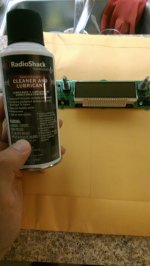
The knobs are easy to fix. Some tuner cleaner from RadioShack fixes those. Now for the buttons. It's a little more complicated. I paid $320 to DAC one of those outfits that sends you one without having to send one in first). Then you get $100 back when they receive your old one. I had already tried repairing my original one. Replaced some buttons thinking they were the problem. They are not. When I got the replacement, I found out that the one you send back cannot be tampered with in any way, which mine obviously was. So I wasn't going to get my $100. Anyways, I have a degree in Electronics so I decided what the hell, I'll take apart the replacement and see what they did. Maybe replaced the potentiometers for the fan and temp controls. The new controller's potentiometers didn't work well at all (not responding to turning, skipping settings) Tuner cleaner cured that and they've been working for 6 months now.
I can also tell they removed the LCD. All the button SMD resistors and some diodes are under there as another member pointed out. Also spotted an IC chip which definitely had some suspect solder connections on it. Most of the solder connections are so small you need an eye loupe to really see. I was successful in getting my defroster button to work but in the process for whatever reason could not get the AUTO, TEMP or RECIRC buttons to work anymore. I gave up because I knew I needed some more sophisticated soldering/ desoldering equipment that I don't have. I'm sure all the problems are under that LCD specifically that IC chip and those SMD resistors and arrays. I've been eyeing a solder station to do the job but it's over $500. I still have the Digital AC unit in a box. Might have to get back at it, although I think I may have accidentally lifted one of the traces from the PCB. (wrong tools for the job, maybe the reason why those button don't work) This seems to be a big problem that needs some resolution. Anybody have a spare I can fix? Once I get the new station. I'll do it for free and post the results.
 
Perfect. I'll try cleaning them with tuner cleaner this week and report back. Thanks!

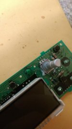
Pull the knobs off and very lightly spray the tuner cleaner down on the shaft down into the body of the potentiometer. Turn the shaft back and forth a few revolutions and repeat. This process is a little better and a little less messy if the circuit board is out (or at least the climate control itself standing vertical) and laying flat so the cleaner flows down into the body instead of more out and into the bottom of the climate control housing.
 
Quick Update: I took the advise from the forum and purchased me a small bottle of tuner cleaner from Radio Shack. Costed me about $10. After taking my climate control apart, I sprayed the tuner cleaner around the climate control knob. Now the issue I originally had where the the digital temperature only ranged from COLD to 72 degrees is gone. You can really feel each gears as you turn the knob. Sometimes you realize common things like getting hot air on newer cars for granted. I'm really excited I now get hot air. :guitar3:


youtube
 

Attachments

  • IMAG0803.jpg
    IMAG0803.jpg
    132.8 KB · Views: 1,304
  • IMAG0804.jpg
    IMAG0804.jpg
    126.1 KB · Views: 1,611
This sounds like a reasonable root cause.

If someone wants to post some detailed pictures, I design circuits for automotive sensors and have a bit of a specialty in this kind of thing, so I might be able to see/confirm the root cause. It sounds like there may some board flexing when the buttons are pushed that maybe stresses those resistor arrays causing them to crack. Seeing only cabin temperatures and not the heat cycling of an engine mounted sensor, these boards shouldn't be seeing so much solder cracking, especially since they are likely leaded solder.

Someone post up some pics of the boards and the way the boards and buttons are mounted. I don't have a digital climate control, so I can't check this myself.

Actually the board sees heat cycles from the small "condomed" bulbs that are in there, and they get quite hot....

As has been mentioned here, if you flex the board you can get it to work sometimes, which is why some people have success by simply pulling it apart and then putting back together again - for a time.
And the flex itself implies that some of the solder joints are bad, which has indeed been the case for all the ones I've seen (and repaired...).

I have never seen bad buttons or pots though I guess if you live in a very dirty/corrosive environment it's possible.

You can very carefully bend up the lcd display from the main board as I have mentioned without desoldering it. Don't do that too many times though, the leads will eventually break. I believe the small resistor arrays may get extra heat under the lcd screen possibly. Seems to be the general problem area anyway.
 
soldering climate control success

Success. I did the soldering with a cheap soldering iron purchased at Harbor Freight. I wondered as I was doing it if purchasing better quality solder would have been worthwhile, because, I believe there are different types with more conductivity (silver) and perhaps some that are less brittle?

All of the buttons now work that didn't previously. The only one that is still weak is the contact for the right dial for the volume of air flow. It does work enough by playing with it that its ok. Perhaps the problem there is in the variable dial itself.

Steps:
1. carefully pry off dash trim
2. unhook different connections so trim comes off far enough to get to air unit.
3. There is a small trim piece around climate control that comes off easily and allows you to get to three screws - one on left and two on right.
4. The connections for air control are hard to get off (for me). Use a miniscrewdriver to push center release while you pull out connections.
5. Black front with controls is snap fit to yellow back shell but pretty easy to open. Be careful when opening this. One while cable connection to disconnect with clips you pry open to side and then cable comes out.
6. The hardest part is getting the board out where it is held in place by clips. There are also three small screws holding the board down. Just try to be patient and careful not putting too much bend on the board getting it out of the plastic enclosure and press fit clips.
7. I soldered each of contact points on the backside of the board for the buttons on the digital air unit. Hold solder iron to contact point with your solder in place, quick touches should make current solder flow and by touching your new solder to tip, you can add some that will add to contact point for a better connection.
 

Members online

No members online now.

Forum statistics

Threads
278,311
Messages
3,554,082
Members
248,016
Latest member
Advally Service

Trending content

Back
Top