SpeedoHealer v4 in 4th Gen

Theoretically wheel speed sensors on our Toyotas are typically simple 2-wire passive magnetic sensors paired with a tone ring that outputs a varying voltage frequency pattern. Which should be similar to the varying frequency output that comes out of the Skid Control ECU, so theoretically you should be able to utilize the SpeedoHealer between the Wheel Speed Sensors much in the same way it is currently utilized between the Skid Control ECU and Combination meter to provide a much more accurate picture of the actual vehicle speed to the entire vehicle. So a simple 4 wire parallel tap into each sensor with the SpeedoHealer outputting it's offset signal should work fine rather than needing 4 stand alone units correct?
I think you would need speedohealers on each signal pair for it to work properly, or build your own speedohealer with multiple inputs/outputs with a raspberry pi or something. Either way, I don't think it would be worth it. The VSC/ABS/etc mostly are concerned with differences in speed between the wheels, more than the overall speed. The functions I can think of that are speed determined are at speeds slow enough that 7% error rate isn't much.
 
I think you would need speedohealers on each signal pair for it to work properly, or build your own speedohealer with multiple inputs/outputs with a raspberry pi or something. Either way, I don't think it would be worth it. The VSC/ABS/etc mostly are concerned with differences in speed between the wheels, more than the overall speed. The functions I can think of that are speed determined are at speeds slow enough that 7% error rate isn't much.

Yeah the more I thought about it today the more I realized I'd need 4 separate channels to handle each wheel correctly. While it does mostly work of different wheel speeds; I do believe the system has set speed zones for things like TRAC/VSC in turns (i.e. G-Force, angle of vehicle, & vehicle speed help determine how much assistance if any is needed via VSC), while 7% isn't as much of an issue I was thinking more in terms of when I plan to run 35" tires. But it is starting to seem like it's more work than it's worth.
 
Added a small line in the first post to notate that you want a SpeedoHealer "Universal" kit vs. their model specific units. [MENTION=145222]4rcybr[/MENTION] for pointing that out.

Also in regards to the above idea of using a theoretical 4-Channel Speedohealer-like device to "correct" sensitivity in the VSC/TRAC system, it'd probably wouldn't do all that much. I threw the idea out at an FTS out of curiosity a while back and he pointed out that the Yaw Rate sensor is going to have a more immediate effect rather than individual wheel speed as a whole. So Yaw Rate Drop Bracket mod soon? lol
 
So for those of you who are not aware, when you change the physical tire size of your vehicle you will affect the speedometer's accuracy. For example a common tire upgrade on this forum is to go from the stock P265/65R17's (30.5") to LT285/70R17's (32.7") which comes to a 7% difference in diameter. This means that your speedometer reads 7% less than what you are actually doing (I found that at about 80mph I was doing 85mph or so.) You can figure out what the percentage difference is in your tires by using a tire calculator like the one on Tacoma World:
Tire Size Calculator - Compare Tire Sizes

There's a product called SpeedoHealer by Healtech Electronics (HealTech Electronics Ltd. ? Smart Tech for your Ride ? SpeedoHealer v4) that corrects this issue in motorcycles (apparently digital speedometers in motorcycles are notoriously inaccurate), conveniently the VSS (Vehicle Speed Sensor) in motorcycles is the same in most automobiles. I want to thank 4Mudder on the Toyota120 forums for referring me to this product and his write up (Speedometer correction - Toyota 120 Platforms Forum)

NOTE- You'll want to use the SpeedoHealer "Universal" kit as the wiring will match what I did. :)

Now I installed mine a bit differently than 4Mudder's and I figured I'd post how I did it in case others wanted to see other ideas for installation.

First things first lets get the wire colours of the SpeedoHealer v4 out of the way, I found this slightly confusing at first because they didn't show a diagram or table and instead used verbiage to somewhat describe what the wires did.

Red- 5v-12v Power Source
Black- Ground
White- VSS (Vehicle Speed Sensor) Input
Green- VSS Output

Now lets get the combination meter out of the vehicle so we can get to the wires. This is all straight forward, you'll find two 10mm bolts on the lower kick panel under the driver's side that need to be removed and everything else just pulls off with snap clips. The combination meter is held down by three 10mm screws that go into the dash and two 10mm bolts that secure the connectors to the combination meter as illustrated in the following picture. Do note that the gold 10mm bolts will "click" when tightened, you only need them to click once to have the connectors nice and tight when reinstalling.

View attachment 131063

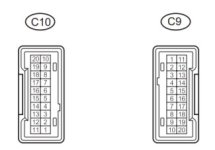
The next thing we need to do is determine what wires we're going to cut into, if you happen to have an EWD (Electrical Wiring Diagram) for 4th Gen you'll find (after digging a bit) that Pin#4 (Grey with Red Stripe wire) on Connector C9 is the VSS Input from the Skid Control ECU. You'll want to cut that off about an inch or two from the connector and splice the White wire to the end feeding from the Skid Control ECU and then splice the Green Wire into the end feeding into the combination meter, like so:

View attachment 131064
View attachment 131065

Now that we have the VSS signal taken care of, you'll want to get power and ground, this is mainly where I differed from 4Mudder's installation procedure. I figured that the unit is not drawing a significant amount of amperage to operate (as it just shifts the VSS signal by a calculated percentage) and thus took that gamble that it could be spliced into the combination meter's power supply (it was a gamble because I didn't have a small amp clamp to bench test its actual amperage draw and so I based my guess on experience.) I tapped into Pin# 5 (Black with Orange Stripe wire) of Connector C10, this is the 12v Fused Power Supply for the combination meter (the 10Amp IGN Fuse located under the dash) and then for ground I tapped Pin#13 (Solid Brown wire) on Connector C10 for the ground. Pin# 13 is what is referred to as a "Dirty Ground" which means it is used for many various functions such as the small motors for the speedo, tach, ect. and using this ground won't cause issues with sensor readings or computer function such as using a "Clean Ground" would.

View attachment 131062

I then routed my SpeedoHealer harness behind the dash bar and fuse block and to the actual SpeedoHealer unit which I stuck to the metal reinforcement plate for the kick panel. It comes with adhesive velcro tape and it perfectly fit between the fuse block and the metal panel right here.

View attachment 131066

Now the main reason I routed it here was for ease of access in case I ever needed to do anything with the unit. Where it is now is out of the way, but easily accessed; with the added bonus of looking almost factory (you all know how obsessed I get about that! :ohwell:)

View attachment 131067

After its all nice and installed, just follow the instructions on the paperwork that comes with it to set your SpeedoHealer and enjoy a now accurate speedometer! I will also note that the SpeedoHealer v4 comes with a dual memory function, which means you can switch between two different settings; I would assume this is a nice bonus for those of you who run smaller street tires and larger off-road/winter tires.

I cannot thank you enough for this [MENTION=66389]BlackWorksInc[/MENTION] It has been really helpful for my install.

I was wondering if you (or anyone else) happened to know if you are running a speedo healer (set to 7 for 285/70/17) and then also have a Scan Gauge II that you are running do you need to set the Scan Gauge II to 7% wheel difference as well, or does it pick up on the adjustment from the speedo healer?

I had my Scan Gauge II set to 0% and the mileage was horrendous. Set it to 7% and I am getting roughly 13 city MPG.

Doesn't matter all that much, but just curious what to run the Scan Gauge II at to get an accurate reading.

Thanks again!
 
I cannot thank you enough for this [MENTION=66389]BlackWorksInc[/MENTION] It has been really helpful for my install.

I was wondering if you (or anyone else) happened to know if you are running a speedo healer (set to 7 for 285/70/17) and then also have a Scan Gauge II that you are running do you need to set the Scan Gauge II to 7% wheel difference as well, or does it pick up on the adjustment from the speedo healer?

I had my Scan Gauge II set to 0% and the mileage was horrendous. Set it to 7% and I am getting roughly 13 city MPG.

Doesn't matter all that much, but just curious what to run the Scan Gauge II at to get an accurate reading.

Thanks again!

Hmm... I am not sure. It depends on how the Scangauge is modifying the data. The Speedohealer intercepts the speed signal from the ABS module to the combination meter, which is where most of the car pulls speed data from. But the ECM has a direct line to the ABS so it could pull uncorrected data for various purposes via that dedicated communication line. I don't know what and how Scangauge is modifying that data.
 
Hmm... I am not sure. It depends on how the Scangauge is modifying the data. The Speedohealer intercepts the speed signal from the ABS module to the combination meter, which is where most of the car pulls speed data from. But the ECM has a direct line to the ABS so it could pull uncorrected data for various purposes via that dedicated communication line. I don't know what and how Scangauge is modifying that data.

I remembered the other day that the ScanGauge has the ability to display speed on the screen, so I was able to adjust using that info. Needed a +2% shift. Just thought I would share in case anybody else reads this down the road and is trying to figure it out as well.
 
I've tried to get the SpeedoHealer V4 to work with my 4R after following these directions, and haven't had much luck.

I reached out to Speedohealer, and it appears there was a recent hardware change made to these units that is affecting how they perform with our trucks.

Have some additional testing to do, but figured I'd post beforehand to get y'alls thoughts.
 
I've tried to get the SpeedoHealer V4 to work with my 4R after following these directions, and haven't had much luck.

I reached out to Speedohealer, and it appears there was a recent hardware change made to these units that is affecting how they perform with our trucks.

Have some additional testing to do, but figured I'd post beforehand to get y'alls thoughts.

I installed mine on 2/3/2018 and it worked fine, I followed this guide.

It seemed relatively easy and straightforward, though it was long enough ago I don't remember every detail.
 
I installed mine on 2/3/2018 and it worked fine, I followed this guide.

It seemed relatively easy and straightforward, though it was long enough ago I don't remember every detail.

According to them, the hardware change occurred within the last 6 months.

I am curious now, though. Would you be up for testing my Speedohealer in your vehicle to see if it's potentially an installation error, or if the hardware changes are in fact the cause of the issue?
 
Last edited:
According to them, the hardware change occurred within the last 6 months.

I am curious now, though. Would you be up for testing my Speedohealer in your vehicle to see if it's potentially an installation error, or if the hardware changes are in fact the cause of the issue?

Yeah I probably could, I'll PM you.
 
Just so know, I'll be waiting for an update. I'm glad I checked the forum before purchasing.

Sent from my XT1710-02 using Tapatalk

I plugged it in to mine and it appeared to work fine, so we think its installation error.
 
I plugged it in to mine and it appeared to work fine, so we think its installation error.
I just received mine, conveniently the day I get new wheels and tires. So that's good to know. Thanks.

Sent from my XT1710-02 using Tapatalk
 
Apologies for the drama and confusion it wound up being a 100% installation error.

Was originally spliced into the incorrect wire for ground. My fault for rushing the install and not paying attention.

All is working as expected now.
 
[MENTION=102822]JONBOY345[/MENTION] I'm curious as to what was the behavior when you had it installed incorrectly? Was your speedometer sporadic or just dead?
 
[MENTION=102822]JONBOY345[/MENTION] I'm curious as to what was the behavior when you had it installed incorrectly? Was your speedometer sporadic or just dead?

It was dead. Wouldn't even move. I do have a strange behavior right around 55-56 MPH where the needle drops rapidly for a split second before returning to either 54ish or 57ish depending on if I'm accelerating or not.

Edit: The needle drop issue here was a known issue with the speedohealer firmware. They replaced mine under warranty free of charge and after about a month of waiting for it in the mail.
 
Last edited:
Here's the layout of the C9 & C10 connectors for those who will be adding this in the future. I would double check you are using the correct pin and not base it just on wire color. I thought I had hooked up to the "brown" wire only to find out later that it was brown with a red stripe. Red stripe was difficult to see in low light. This goof caused my VSC and Engine light to come on, the speedometer to not work, and the fuel gauge to float between empty and the actual level.

Instagram post by [email protected] • Apr 25, 2019 at 12:46am UTC
 

Attachments

  • comboMeter-C9C10.jpg
    comboMeter-C9C10.jpg
    14.2 KB · Views: 639
Here's the layout of the C9 & C10 connectors for those who will be adding this in the future. I would double check you are using the correct pin and not base it just on wire color. I thought I had hooked up to the "brown" wire only to find out later that it was brown with a red stripe. Red stripe was difficult to see in low light. This goof caused my VSC and Engine light to come on, the speedometer to not work, and the fuel gauge to float between empty and the actual level.

Instagram post by [email][email protected][/email] • Apr 25, 2019 at 12:46am UTC

Yep. That's exactly what happened to me. Installed originally close to dark and couldn't see what I was doing very well. I should have mentioned it but was in a hurry when I made my last post. Glad you got it figured out.
 
Last edited:

Members online

Forum statistics

Threads
278,316
Messages
3,554,111
Members
248,016
Latest member
Advally Service

Trending content

Back
Top