SPUNK build thread

4Runner, now playing everywhere!

Howdy y'all!

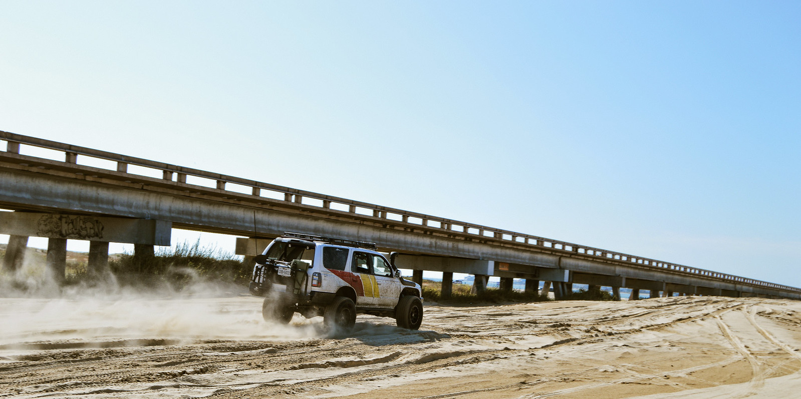
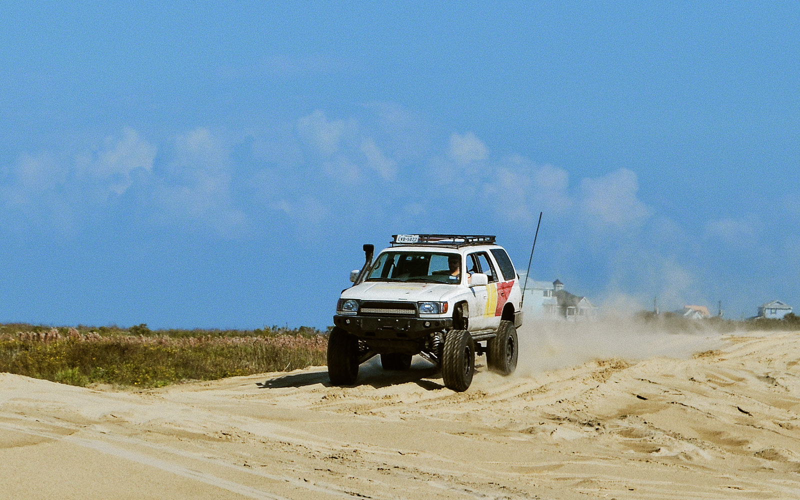
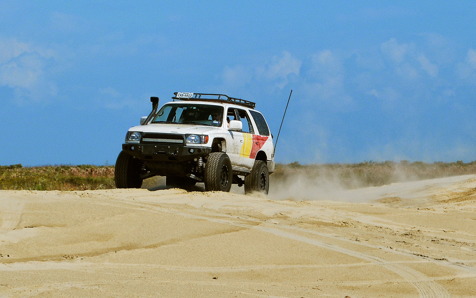
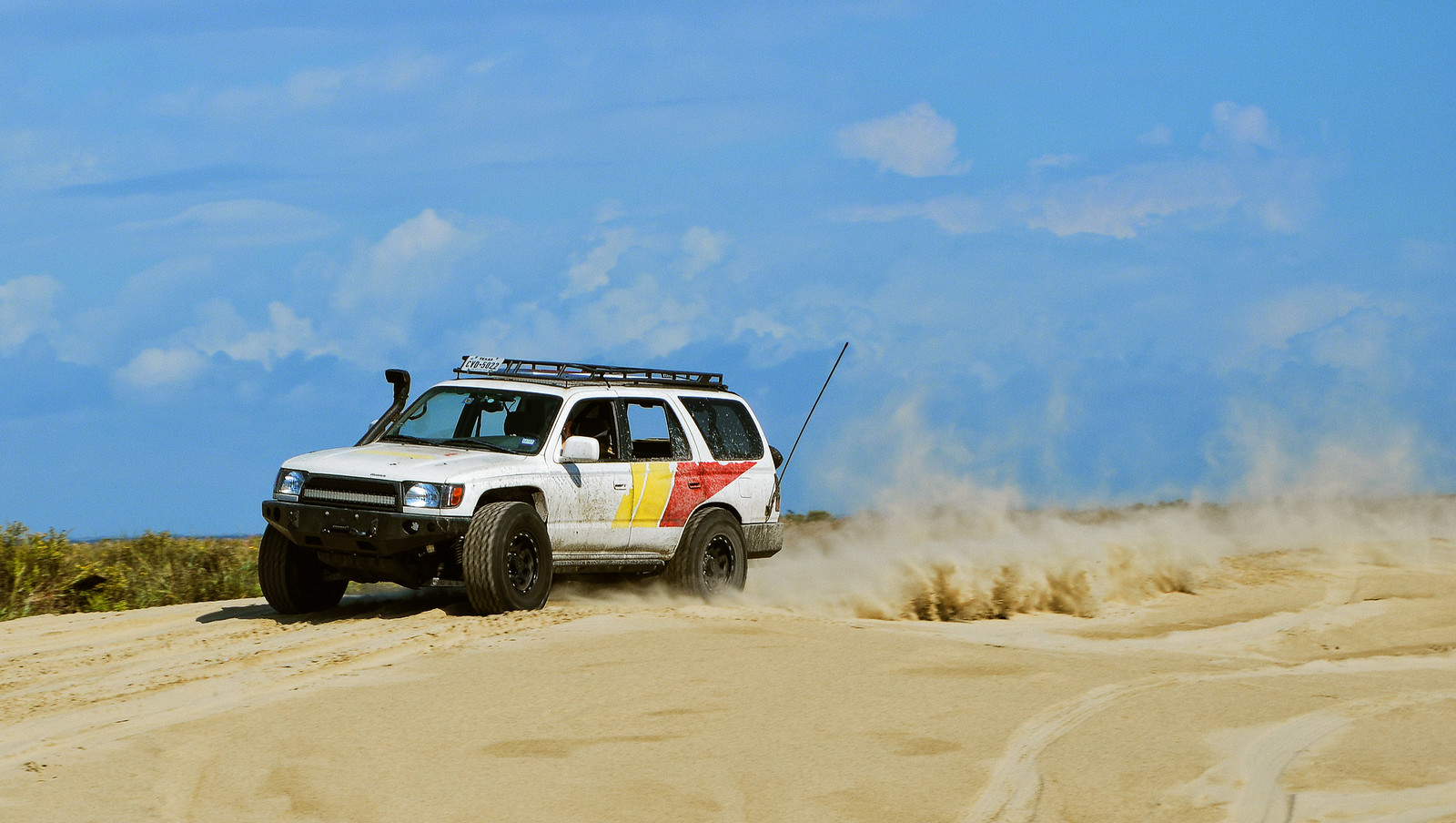
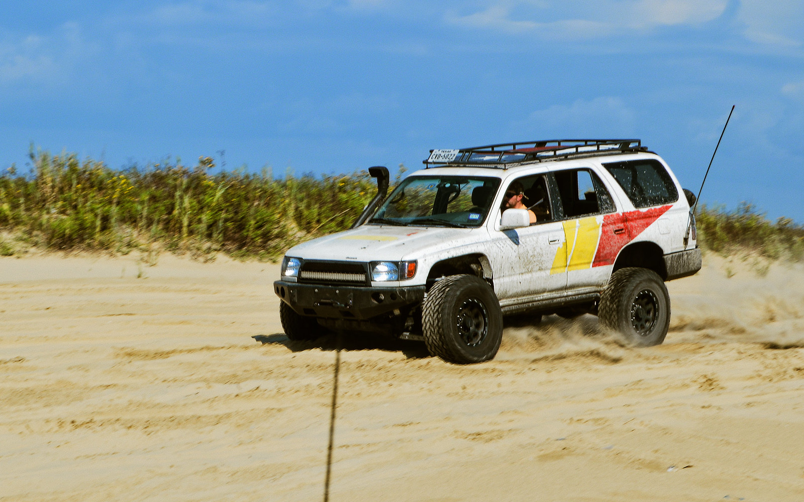
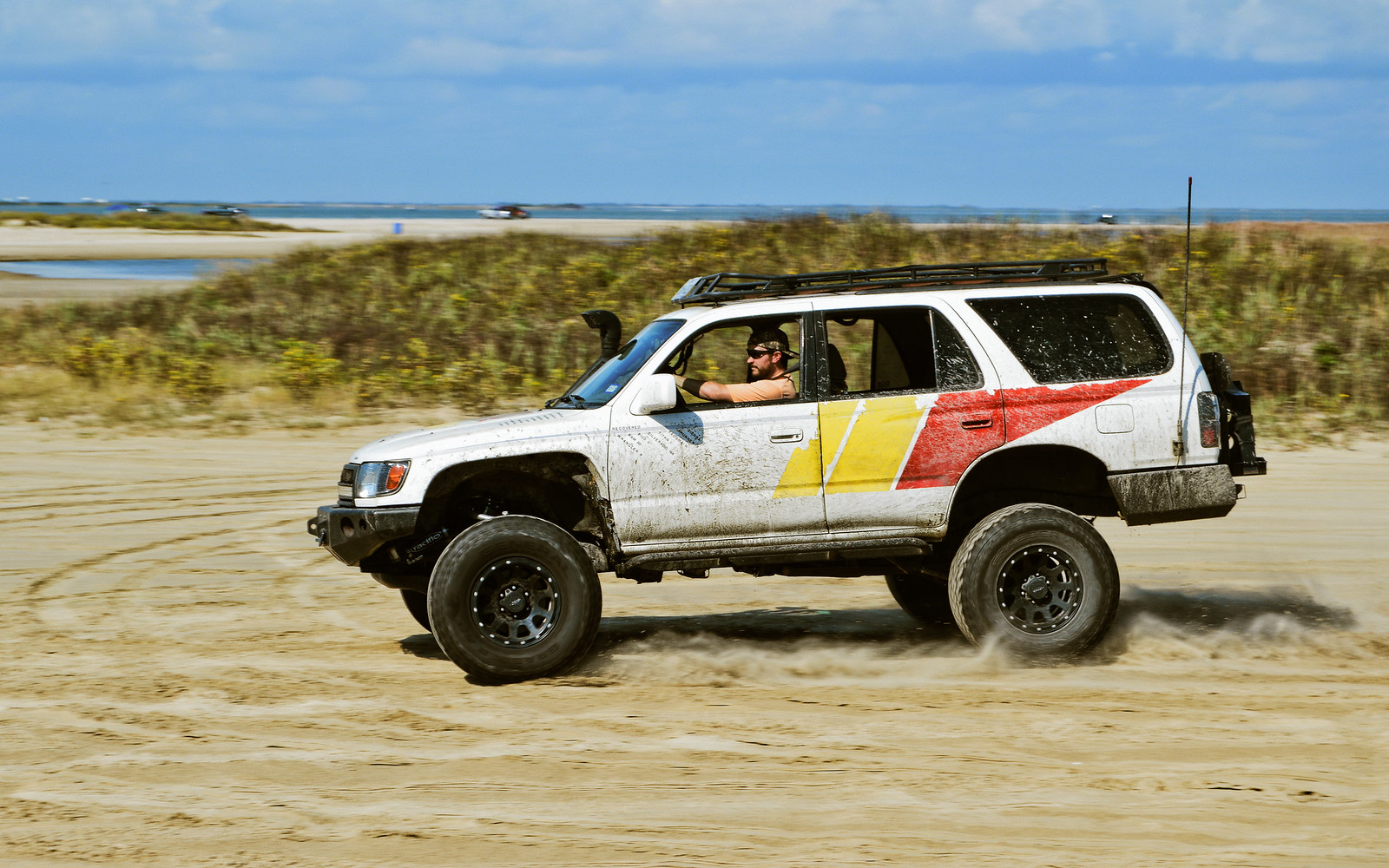
So here is the first photos from the mayhem on November 4th.

Yes, videos were made! I am going to upload them as soon as I get them.

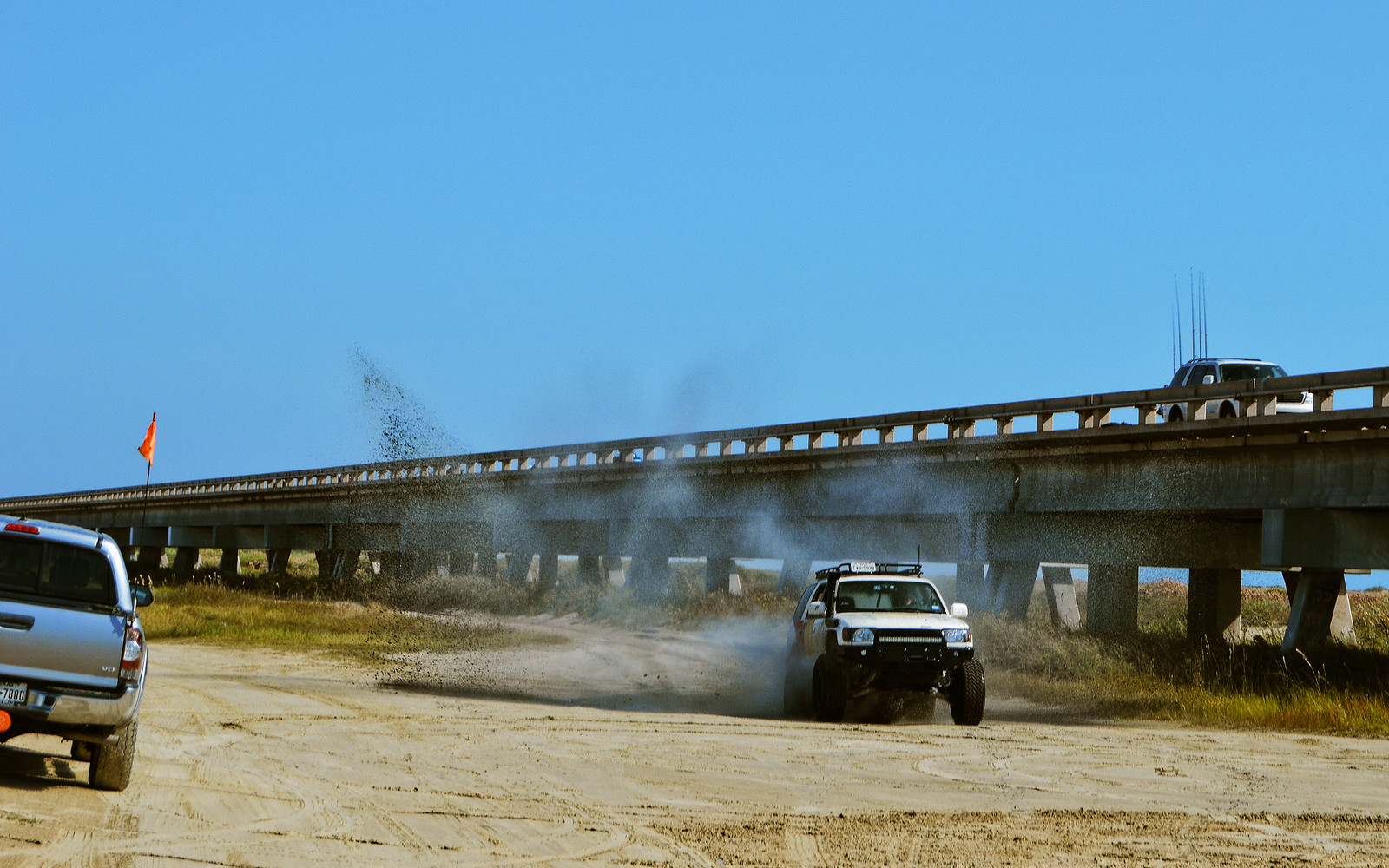
For now, here are photos from the fun. Most of these were taken between 35-50 mph, a gentle test. Enjoy!


38164687926_88945a7bd1_h.jpg


38164679166_786f6db1ca_h.jpg


38164672146_778b9b8ecf_h.jpg


38164671256_3f0922a059_h.jpg


38220356911_7af25b922a_h.jpg


38220228021_32b0e5fd90_h.jpg


38164662406_7684d35be9_h.jpg
 
Hahaha. Great photos! Can't wait to see some videos. Do you remove the rear spare and all the extra weight on your swing out when you plan to do some aggressive driving? I can't imagine that hitting whoop dee dos at speed would do any favors for a fully loaded rear swing out bumper. That might be a lot to ask a rear hinge to handle.
 
Hahaha. Great photos! Can't wait to see some videos. Do you remove the rear spare and all the extra weight on your swing out when you plan to do some aggressive driving? I can't imagine that hitting whoop dee dos at speed would do any favors for a fully loaded rear swing out bumper. That might be a lot to ask a rear hinge to handle.

Yep! I am even planning to remove the sway-carrier and the roofrack entirely, and they'd be replaced with the upcoming roll cage. :biggrin2:

Here's a video!

 
Yep! I am even planning to remove the sway-carrier and the roofrack entirely, and they'd be replaced with the upcoming roll cage. :biggrin2:

Here's a video!


That's some impressive suspension eating up the terrain. How fast were you going in that video?
 
Update. Shedding weight

Hi folks!

Just a quick update, I have shed weight of the 4Runner. Roof Rack is off, Rear tire carrier is off, and a few haphazard accessories. Even though the rig is lighter and better cornering, regearing is likely in my future if I want to maintain the larger tires--probably 5.29's.

On that note, I have sourced an E-locker axle from an FJ cruiser (Spunk has been a blast to wheel open though). I hope to start a rear axle conversion to regear, add disc brakes, add a locker for grins, and widen the tract to near-match the width of the long travel track width in the front. I will remove the top perches and relocate the suspension mounts.

Cheers!

40332175994_3c78f52a9f_b.jpg


40147747445_e7c6f006a5_b.jpg
 
Looking forward to seeing an axle swap! Would a tundra rear axle be a better swap to get the same track width as the front? I think the tundra axle is 66” WMS. What’s your plans for suspension? 3-link it?
 
Kowabunga!

Looking forward to seeing an axle swap! Would a tundra rear axle be a better swap to get the same track width as the front? I think the tundra axle is 66” WMS. What’s your plans for suspension? 3-link it?

Perhaps! So long as I could get 5.29's for it, that would be fantastic. However, at least this way I can pull off an OEM locker for now.

Update!!

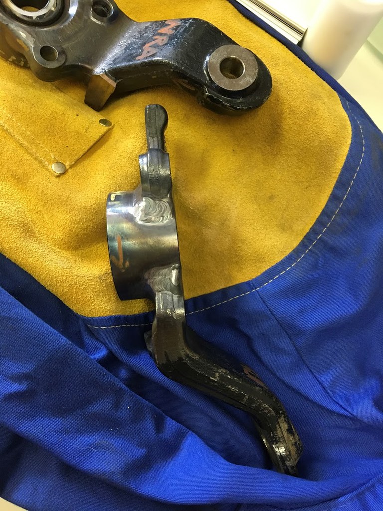
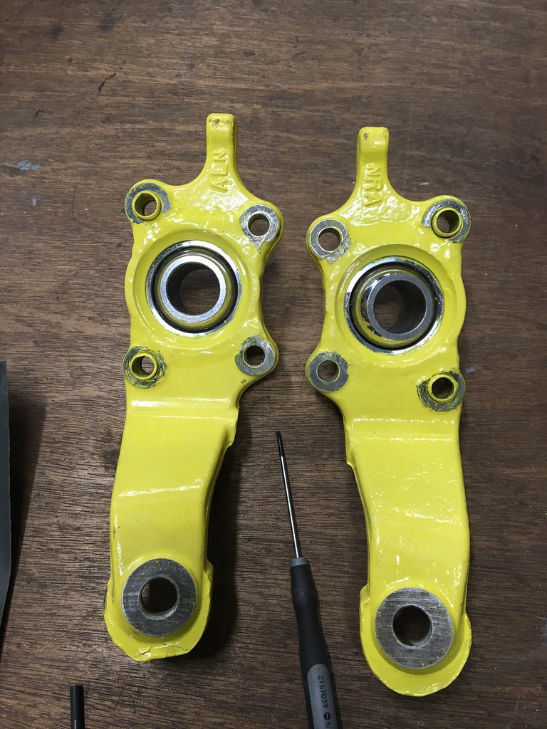
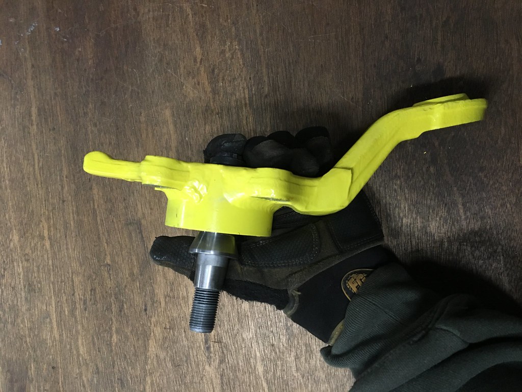
Uniballs are welded up. Dry fit is tonight!

KOWAHBUNGAH! :drum:

41260244411_8160d9c3cd_b.jpg


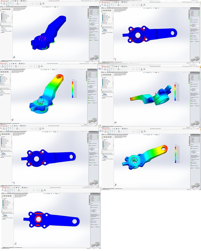
A simple analysis I used to validate the weld sizes I chose.

40364498495_c7d223bc25_b.jpg
 
Perhaps! So long as I could get 5.29's for it, that would be fantastic. However, at least this way I can pull off an OEM locker for now.

Update!!

Uniballs are welded up. Dry fit is tonight!

KOWAHBUNGAH! :drum:

41260244411_8160d9c3cd_b.jpg


A simple analysis I used to validate the weld sizes I chose.

40364498495_c7d223bc25_b.jpg


Just out of curiosity, what kind of load conditions did you use for that FEA?
 
Just out of curiosity, what kind of load conditions did you use for that FEA?

:director: Disclaimer: The following text below is for information only, and it is provided for educational purposes. Consider at your own risk. :blah:

It was very basic. I considered the typical axial static load limit of the uniball, using that force as a bending moment about the four mounting bolts of the balljoint to the spindle. For the 1" FK 17-4 rod ends, their axial load limit are around 19-20kip.

Only the four flange faces that touch the steering knuckle were considered fixed surfaces. Everything else in this analysis, including the through holes of the four flange bolts were spaghetti. The axial force was applied to face of the uniball, Dimensions B to O on FK drawings.

In this one instance, the Radial stress published for the uniballs (~55kip) are near-AOK, since that is practically a shear on the effective area of the welds (AWS D1.1 Table 2.3). I planned to use ER70S-2 filler material with GTAW, so I based the design's min yield point at 50KSI for the C.S. to 4130 weld without PWHT (known from past data with a few PQR's). At that point, it was kinda straight forward to determine minimum weld dimensions that still provide the warm and fuzzies. Top weld is a partial penetration groove (~60-80 degree inlcuded bevel, approx .19" deep [variance in angle due to my grinding skills]), whereas the bottom weld is a fillet (approx .19" size).

 
:director: Disclaimer: The following text below is for information only, and it is provided for educational purposes. Consider at your own risk. :blah:

It was very basic. I considered the typical axial static load limit of the uniball, using that force as a bending moment about the four mounting bolts of the balljoint to the spindle. For the 1" FK 17-4 rod ends, their axial load limit are around 19-20kip.

Only the four flange faces that touch the steering knuckle were considered fixed surfaces. Everything else in this analysis, including the through holes of the four flange bolts were spaghetti. The axial force was applied to face of the uniball, Dimensions B to O on FK drawings.

In this one instance, the Radial stress published for the uniballs (~55kip) are near-AOK, since that is practically a shear on the effective area of the welds (AWS D1.1 Table 2.3). I planned to use ER70S-2 filler material with GTAW, so I based the design's min yield point at 50KSI for the C.S. to 4130 weld without PWHT (known from past data with a few PQR's). At that point, it was kinda straight forward to determine minimum weld dimensions that still provide the warm and fuzzies. Top weld is a partial penetration groove (~60-80 degree inlcuded bevel, approx .19" deep [variance in angle due to my grinding skills]), whereas the bottom weld is a fillet (approx .19" size).

I take it you do this sort of thing for a living? I use basic FEA at work for preliminary design but have about zero formal training on it. The welding calculations are Greek to me, but something I've been curious about.
 
I take it you do this sort of thing for a living? I use basic FEA at work for preliminary design but have about zero formal training on it. The welding calculations are Greek to me, but something I've been curious about.

Yes. I am a welding engineer in O&G. If you are into a little light reading, I suggest skimming through this book. It does a fantastic job at translating all the Greek.
 
Boing!


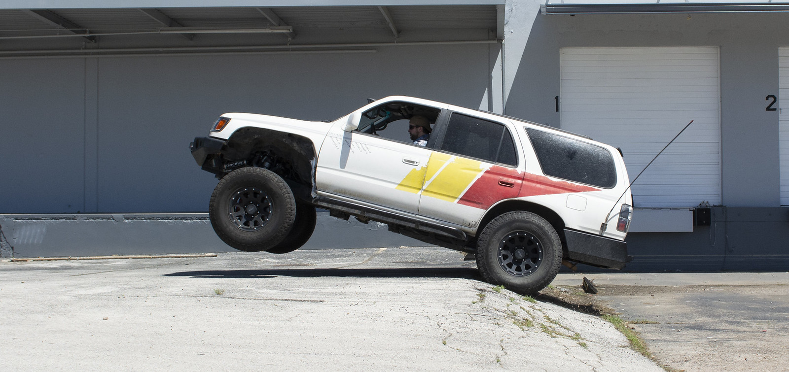
That was jump 8 of the testing. The LBJ's are fantastic. Some more photos may show up as well.

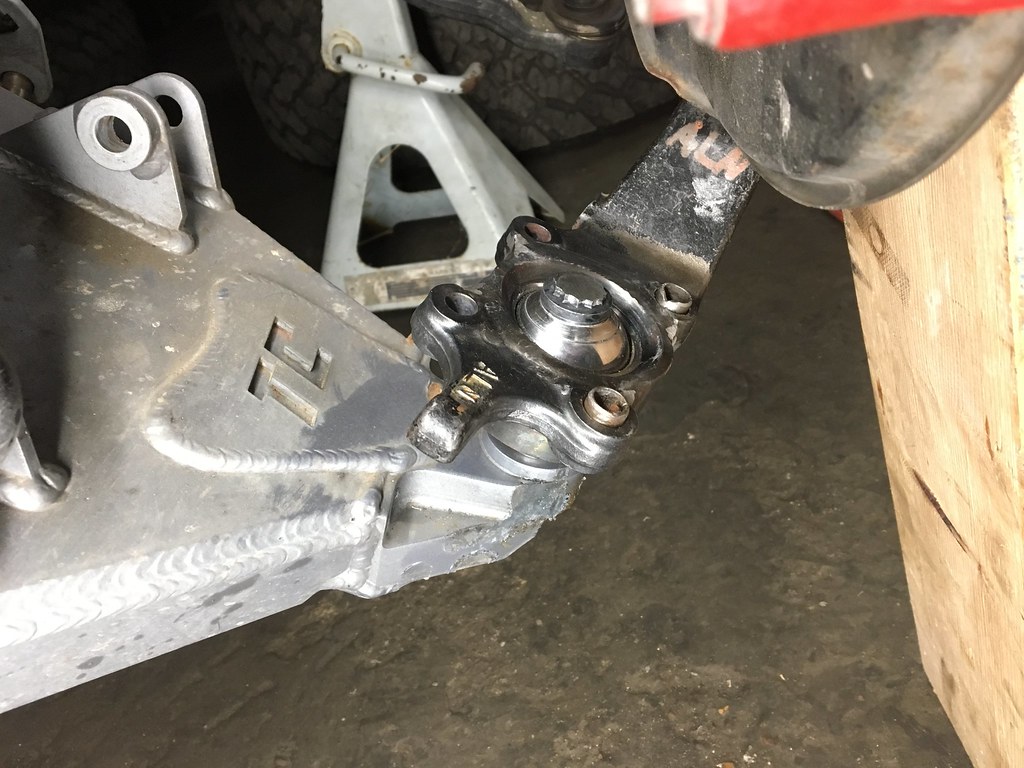
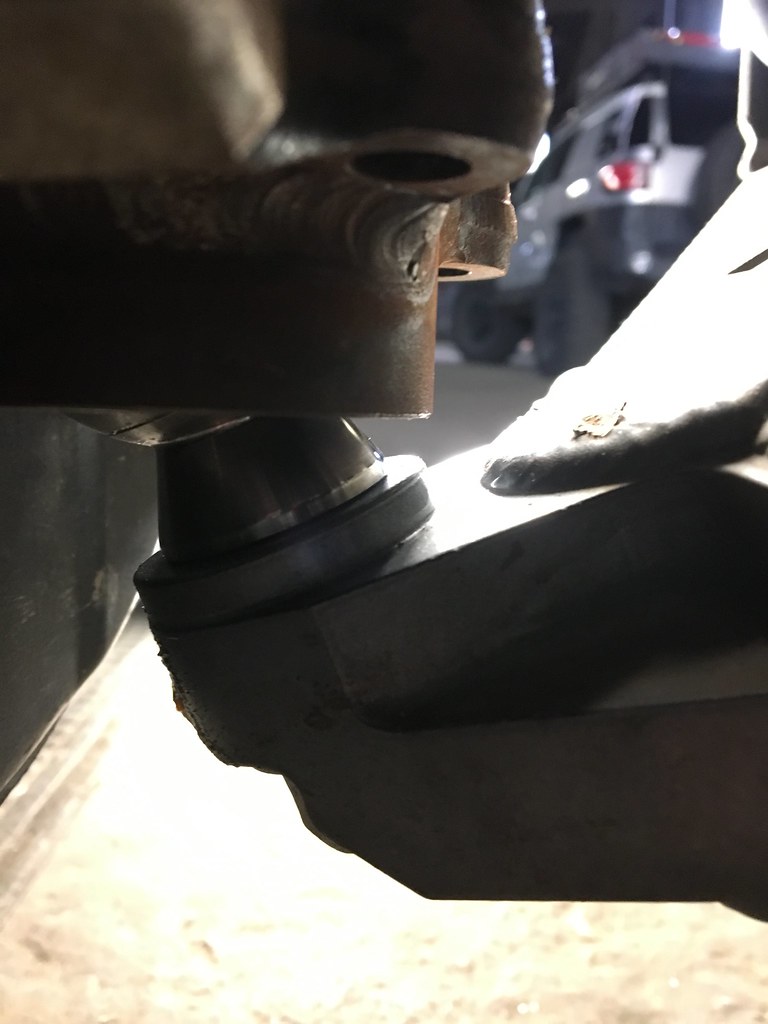
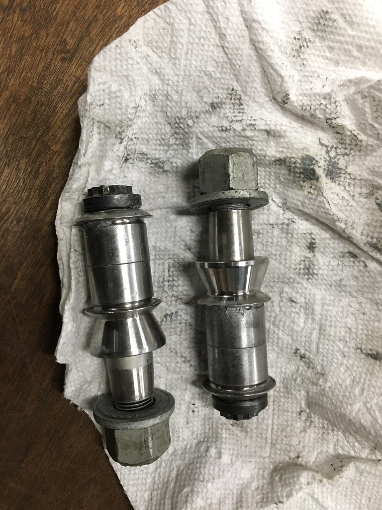
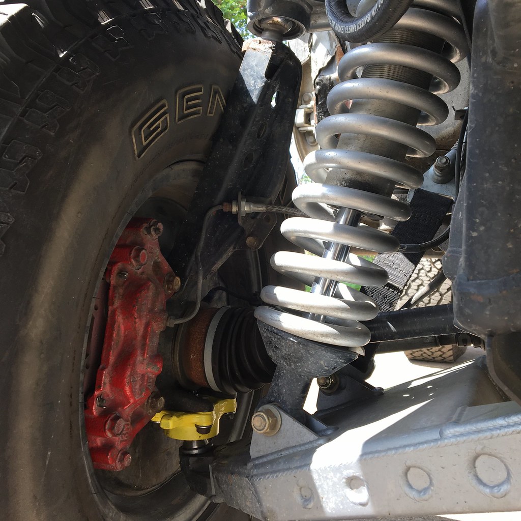
Here are extra photos of the balljoint install. Enjoy!

39678264540_dfbfa0c0b9_b.jpg


41444621582_523a4c19ef_b.jpg


39678216190_2f558f9455_b.jpg


40593252915_13cf8d6011_b.jpg


39678192770_8db728f7a0_b.jpg


26615257957_f8c5124ca7_b.jpg
 
Nice! Couple of quick questions:

1 - Any concern with not having a castle nut/cotter?
2 - Any issues getting a grip on the top of the bolt? Looks like you had to cut it down some?
3 - Any problem with the mounting surface near the 4 bolts from the welds?

For some reason my LBJ start puking after about 5k with my long travel so this is looking goooooood!
 
Nice! Couple of quick questions:

1 - Any concern with not having a castle nut/cotter?
2 - Any issues getting a grip on the top of the bolt? Looks like you had to cut it down some?
3 - Any problem with the mounting surface near the 4 bolts from the welds?

For some reason my LBJ start puking after about 5k with my long travel so this is looking goooooood!

1- Nope. Other long travel setups with uniballs do not have a castle nut/cotter on the bottom side. That is the case on my FJ.
2- Nope. That bolt is from the bonkers bolt grade above grade 8, and it was still able to take 125 ft lbs of torque on the head.
3- Nope. I used cut washers on the bottom side to mate the bolts flat to the balljoint.
 
Well damn, if you ever get the urge to sell a set, I'll buy!

Fantastic!

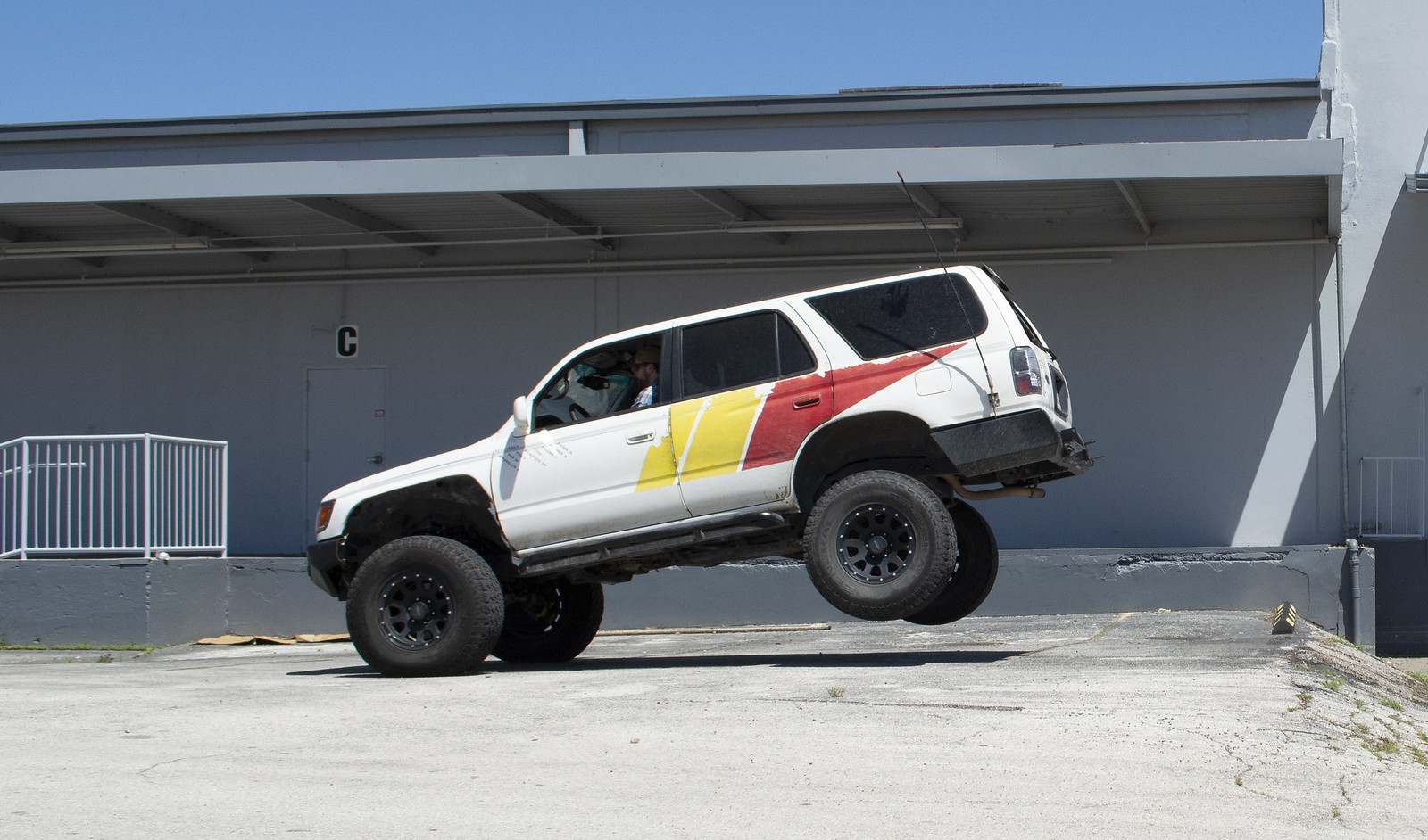
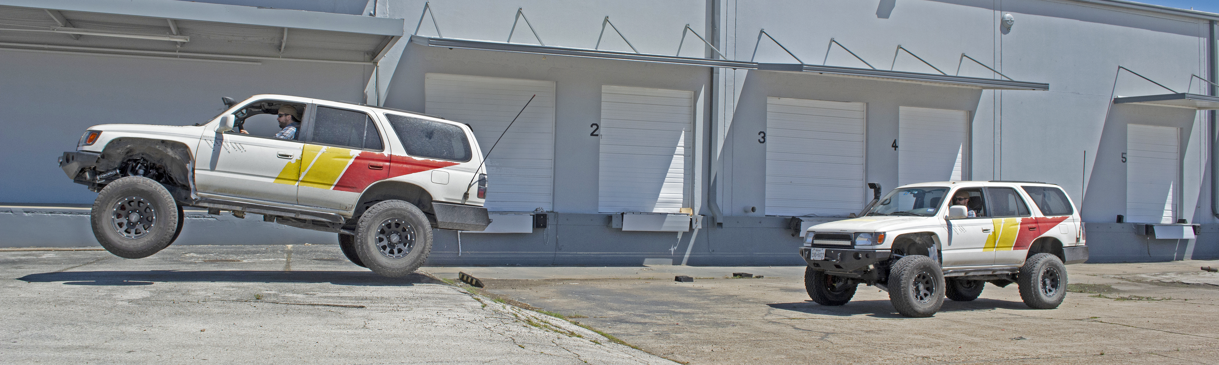
Here are higher resolution photos from the jump street, plus one photo-merge. They were taken with a dslr with gentler jumps, whereas the youtube video was done with an Iphone on the last test jump.

For those who wonder why the front tires look larger than the rear, it's because they are physically closer to the camera with the wider wheel track in the front. The tire size is 295/75R16's.

27675231688_ff304f6a9e_h.jpg


40833914274_30ac37dd77_h.jpg


41504288012_dec576b2e3_o.png
 

Members online

No members online now.

Forum statistics

Threads
278,306
Messages
3,554,045
Members
248,016
Latest member
Advally Service

Trending content

Back
Top