:director: Disclaimer:
The following text below is for information only, and it is provided for educational purposes. Consider at your own risk. :blah:
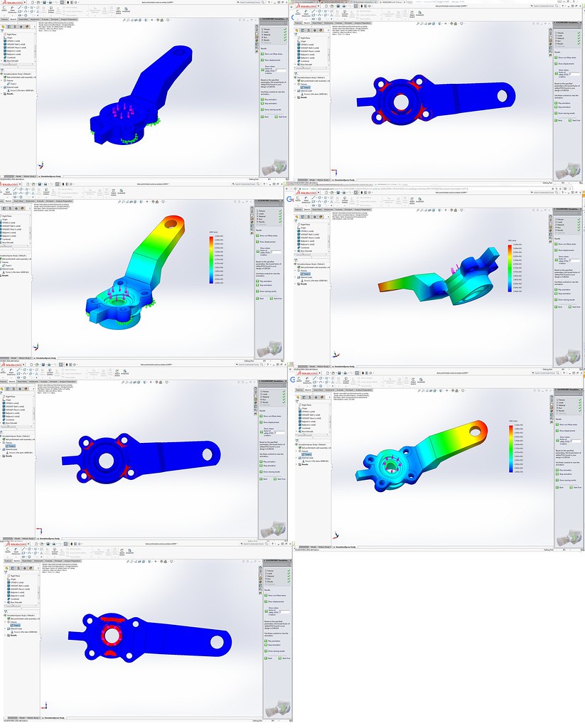
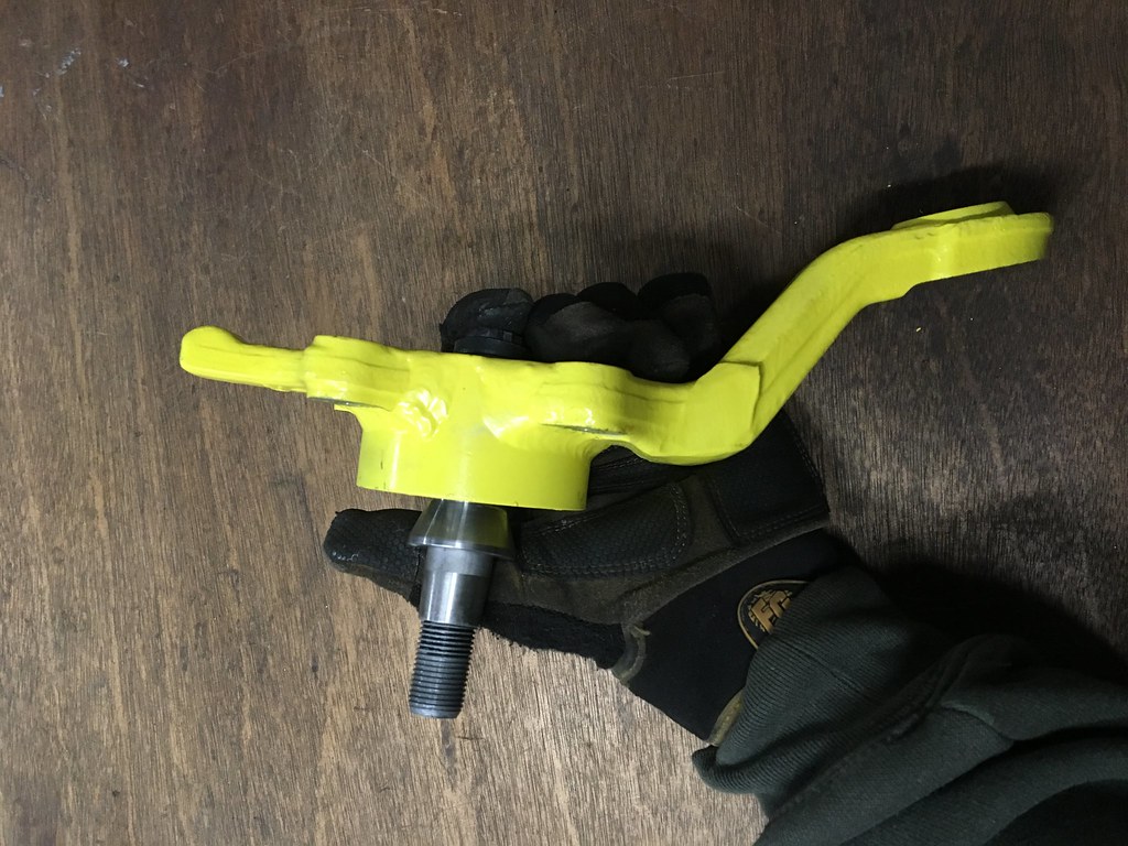
It was very basic. I considered the typical axial static load limit of the uniball, using that force as a bending moment about the four mounting bolts of the balljoint to the spindle. For the 1" FK 17-4 rod ends, their axial load limit are around 19-20kip.
Only the four flange faces that touch the steering knuckle were considered fixed surfaces. Everything else in this analysis, including the through holes of the four flange bolts were spaghetti. The axial force was applied to face of the uniball, Dimensions B to O on
FK drawings.
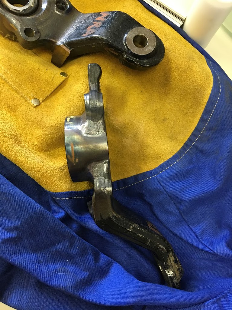
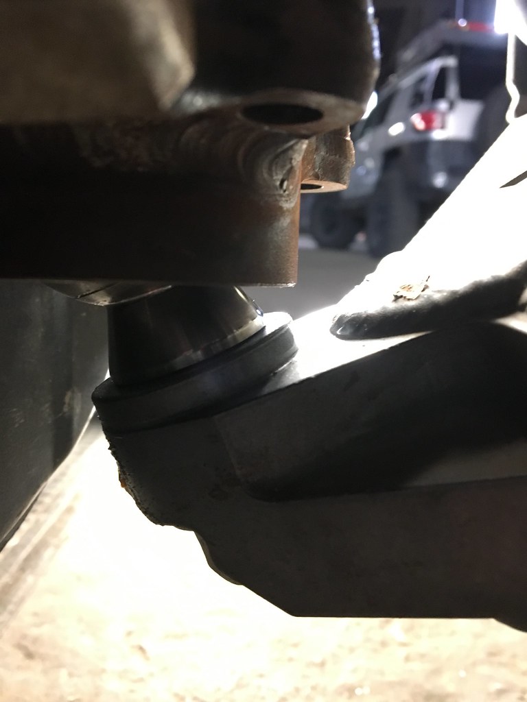
In this one instance, the Radial stress published for the uniballs (~55kip) are near-AOK, since that is practically a shear on the effective area of the welds (AWS D1.1 Table 2.3). I planned to use ER70S-2 filler material with GTAW, so I based the design's min yield point at 50KSI for the C.S. to 4130 weld without PWHT (known from past data with a few PQR's). At that point, it was kinda straight forward to determine minimum weld dimensions that still provide the warm and fuzzies. Top weld is a partial penetration groove (~60-80 degree inlcuded bevel, approx .19" deep [variance in angle due to my grinding skills]), whereas the bottom weld is a fillet (approx .19" size).