Switch-pro SP9100

Ground

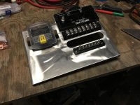
I just got my SP9100 and I’m trying to sort that and a dual battery install at the same time. Where are you running your ground from? The instructions contradict between straight to the negative batt. Terminal and a good frame ground. Also, I’m running my power from the batt. To a circuit breaker(150A) then through a fuse block and to the switch pros. See any issues?
 

Attachments

  • 1D2BFE78-3FAD-43AE-88DD-60E94824DF8D.jpg
    1D2BFE78-3FAD-43AE-88DD-60E94824DF8D.jpg
    131.4 KB · Views: 4,919
I connected the hot wire directly to the battery lug, and the negative to a ground lug I mounted next to the controller and grounded to the battery.

All my load circuits use a full ground wire back to this ground lug, never a chassis ground, to avoid corrosion and vibration related problems later. Many electrical problems can be traced back to the use of multiple different chassis grounds.

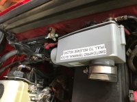
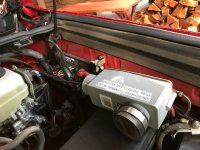
I've got the SwitchPro 9100 mounted immediately aft of the engine fuse ox on the inner wall, with a terminal block from Home Depot handling all the load connections in one easy-to-see place. I then enclosed this in a conduit box for protection and mounted it atop the engine fuse box lid. The result is compact and easy to diagnose and add to.

For the ARB Twin, use a relay, since it draws 57A and the max a SwitchPro circuit (5-8) can handle is 35A. Most everything else can be run directly off the SwitchPro circuits.

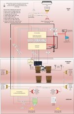
I'm an engineer/nerd, so here is my wiring diagram.
 

Attachments

  • Wiring Diagram.jpg
    Wiring Diagram.jpg
    131 KB · Views: 8,592
  • IMG_4774.jpg
    IMG_4774.jpg
    91.9 KB · Views: 3,067
  • IMG_4763.jpg
    IMG_4763.jpg
    81.8 KB · Views: 2,778
  • IMG_4765.jpg
    IMG_4765.jpg
    104.9 KB · Views: 2,825
  • IMG_4767.jpg
    IMG_4767.jpg
    75.5 KB · Views: 2,734
Last edited:
Also, on your mount, make sure to leave lots of space around the terminal strip. Your lugs and wires will stick out a ways, and you don't want them to physically rub on the SwitchPro case and wear or short. Crimp and heat-shrink them to help reduce the chance of shorts.
 
I just got my SP9100 and I’m trying to sort that and a dual battery install at the same time. Where are you running your ground from? The instructions contradict between straight to the negative batt. Terminal and a good frame ground. Also, I’m running my power from the batt. To a circuit breaker(150A) then through a fuse block and to the switch pros. See any issues?

the sp9100 is rated for 125amps. not sure if upgrading a circuit breaker to 150a is a good idea. The sp9100 will die.. before the breaker trips.
I'm running a 120a circuit breaker for mine, will lose 5 amps.. but protect the sp9100.
 
the sp9100 is rated for 125amps. not sure if upgrading a circuit breaker to 150a is a good idea. The sp9100 will die.. before the breaker trips.
I'm running a 120a circuit breaker for mine, will lose 5 amps.. but protect the sp9100.

Thank you, I hear what you’re saying. My thought on that was; that breaker, or the supplied 125A fuse even, is not the only protection for the unit. Each circuit has the internal MOSFET protection. Since I’ve added a small fuse panel, I upped the breaker to 150A to protect that load as well.

I’m definitely not a pro when it comes to electrical, so I really appreciate input on this. I called Switch-pros on a few of my questions. Their concern was that the unit must see 12V and I “think” I got that covered.
 

Attachments

  • 40C4B0AB-0F22-4E1E-BF26-0B0B7F735E53.jpg
    40C4B0AB-0F22-4E1E-BF26-0B0B7F735E53.jpg
    149.9 KB · Views: 8,078
Last edited:
Thank you, I hear what you’re saying. My thought on that was; that breaker, or the supplied 125A fuse even, is not the only protection for the unit. Each circuit has the internal MOSFET protection. Since I’ve added a small fuse panel, I upped the breaker to 150A to protect that load as well.

I’m definitely not a pro when it comes to electrical, so I really appreciate input on this. I called Switch-pros on a few of my questions. Their concern was that the unit must see 12V and I “think” I got that covered.

I'm probably overthinking and playing too safely.
I'm running a 150a MRBF to 120a circuit breaker on 2awg wire to sp9100
125a mrbf to 100a circuit breaker on 4awg wire to 8 bluesea 8 circuit st.
 
I'm probably overthinking and playing too safely.
I'm running a 150a MRBF to 120a circuit breaker on 2awg wire to sp9100
125a mrbf to 100a circuit breaker on 4awg wire to 8 bluesea 8 circuit st.

I’ve got 2ga. Running to the panel. The short runs are 4ga.
 
I've finished installing a 9100 in my 2018 Offroad Premium, and it works beautifully. Here are a few tips:

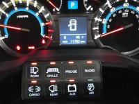
I located the switch module on the top of the steering column at an angle, where it sits beautifully. I can see it clearly, and the color wheel allowed me to match the dash gauge colors perfectly. Since I rarely hit switches when I'm in motion, it does not interfere with steering.

Fuse taps for acc, running lights (dimming the switch pro display) and backup lights to trigger functions are all available directly off the interior fuse block above the driver's left foot. There is a firewall grommet directly in front of that spot, too.

To run wire to the cargo area, I bought a 7 wire "armored" trailer cable and ran this from the engine bay down the left frame rail, wire-tieing it so it doesn't thunk and wear, and up into the left rear fender. There is a small unused grommet you can pop out immediately below the bottle jack tools to feed the cable into that wall bay.

In both the engine bay and rear wall bay, I used a Home Depot terminal block (like the ones pictured in this thread) and enclosed it in a largish grey conduit junction box with a rubber cap from the plumbing department, then used industrial strength velcro to attach the boxes securely to the vehicle. Works great, protects the terminal blocks from damage.

Strobe, dimming, flash, timeouts and bluetooth all worked brilliantly out of the box.

Thumbs-up for a great product.

Erik
 
trigger 1

Ok so I’m starting to understand the concept on how to install this 9100 with all this info I’ve read in the posts. Very helpful! Now I have a couple questions. How do I tap into the high beams to trigger the light bar and/or the fog lamps to turn on when I hit the high beams? And how can I have the high beams on and not have the fog lights turn off if not connected to the trigger option? Hook the fog lights straight to the switch pro instead ? Thanks for the help
 
Currently installing mine onto my new Power Tray main electrical panel, and I am doing a full write up that will be available soon. Functionally, there is little difference between the 8100 and the 9100. There is an increase in power over the previous unit, and some additional features such as multiple button panels per main unit. More info on their website for specifics. IMO the SDHQ mount looks very OEM, but it's low on the dash making it hard to use without taking your eyes completely off of the road. Just something to consider. I will update more with the install as I complete it.

28354399199_2769f34429_c.jpg

Ok.... **disclaimer** noob question coming... **end disclaimer**
So, been searching for information on the Switch Pro 9100 install but seem to be getting partial information from all over. Can someone direct me to a place I may educate myself on WHY I need all of these additional pieces of the puzzle ? I have the SP 9100 and a SDHQ Switch Pro Power Module Mount sitting in a box waiting to be installed, but I need to know what else to buy (as pictured above) and why I need it - how and why, to and from where.
 
Ok.... **disclaimer** noob question coming... **end disclaimer**
So, been searching for information on the Switch Pro 9100 install but seem to be getting partial information from all over. Can someone direct me to a place I may educate myself on WHY I need all of these additional pieces of the puzzle ? I have the SP 9100 and a SDHQ Switch Pro Power Module Mount sitting in a box waiting to be installed, but I need to know what else to buy (as pictured above) and why I need it - how and why, to and from where.


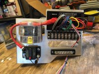
In terms of the picture, you don't really need the bluesea fuse box. I would recommend the terminal block and ground bus bar as it will make your wiring neater and easier. Although both are not necessary. The terminal block just lets you easily disconnect/connect the power wire for the accessory that you're trying to connect. However you could also achieve this with some spade connectors. That way you can easily disconnect the spade connectors and wire in new accessories or switch up the configuration to the switches.
 
I feel your pain, there is not much out there, info or installs.

I bought the Power Tray for the 9100 and a single ARB compressor because I felt this was a great use of space and function.

1. Easy access to Switch Pros
2. Great placement of Switch Pros for running the wires to the cabin.
3. Single compressor meets my needs
4. Blue Sea fuse box. This allows you to power things with a constant power that you don’t want to use a switch for. Like underhood lights with its own switch. Or Mtn4rnr great mod, who needs a grab handle. Etc.
5. Terminal block. MUCH easier to connect and add whatever vs. splicing wires. And much cleaner install. Easier to take off as well.
6. Common bus bar, same as above. All your negative wires go here. Switch Pro or fuse box. Much easier and cleaner
7. Custom cables for your battery. Made the right length.

Anyway, lots of great functional reasons, plus a cleaner more organized engine bay.

ARB / Switch-Pro PowerTray


– PowerTrays
 
Last edited:
I feel your pain, there is not much out there, info or installs.

I bought the Power Tray for the 9100 and a single ARB compressor because I felt this was a great use of space and function.

1. Easy access to Switch Pros
2. Great placement of Switch Pros for running the wires to the cabin.
3. Single compressor meets my needs
4. Blue Sea fuse box. This allows you to power things with a constant power that you don’t want to use a switch for. Like underhood lights with its own switch. Or Mtn4rnr great mod, who needs a grab handle. Etc.
5. Terminal block. MUCH easier to connect and add whatever vs. splicing wires. And much cleaner install. Easier to take off as well.
6. Common bus bar, same as above. All your negative wires go here. Switch Pro or fuse box. Much easier and cleaner
7. Custom cables for your battery. Made the right length.

Anyway, lots of great functional reasons, plus a cleaner more organized engine bay.

thank you srsrogerissrs and SnowYeti....

So, just trying to wrap this around my head better and maybe clear some things up for others reading into this....

The fuse box is present in the MTN4RNR set up because he has "to power things with a constant power" (not turning on and off 'with the Switch-Pro').

Now, the bus bar and terminal block... why do we need both on these ? following a path of wires.... is it a positive wire from the SP to the terminal block and a negative wire from the SP to the bus bar ? Then there will be a positive wire and negative wire from the light (or whatever a person is hooking up to the SP) ?

Thanks in advance... there's not really a followup to the MTN4RNR set up
 
I just got my SP9100 and I’m trying to sort that and a dual battery install at the same time. Where are you running your ground from? The instructions contradict between straight to the negative batt. Terminal and a good frame ground. Also, I’m running my power from the batt. To a circuit breaker(150A) then through a fuse block and to the switch pros. See any issues?
What mount did you use? Looks bugger than powertray. I like the idea of a smaller fuse block and the added breaker. Does it fit into the same location as the Powertray setup?
 
thank you srsrogerissrs and SnowYeti....

So, just trying to wrap this around my head better and maybe clear some things up for others reading into this....

The fuse box is present in the MTN4RNR set up because he has "to power things with a constant power" (not turning on and off 'with the Switch-Pro').

Now, the bus bar and terminal block... why do we need both on these ? following a path of wires.... is it a positive wire from the SP to the terminal block and a negative wire from the SP to the bus bar ? Then there will be a positive wire and negative wire from the light (or whatever a person is hooking up to the SP) ?

Thanks in advance... there's not really a followup to the MTN4RNR set up

The bus bar and terminal block just gives a nice, clean place to wire up the positive and ground from your accessories. With out those you would still have to ground them out somewhere under the hood. I followed MTN4RNR's article on my install under the hood.
 
thank you srsrogerissrs and SnowYeti....

So, just trying to wrap this around my head better and maybe clear some things up for others reading into this....

The fuse box is present in the MTN4RNR set up because he has "to power things with a constant power" (not turning on and off 'with the Switch-Pro').

Now, the bus bar and terminal block... why do we need both on these ? following a path of wires.... is it a positive wire from the SP to the terminal block and a negative wire from the SP to the bus bar ? Then there will be a positive wire and negative wire from the light (or whatever a person is hooking up to the SP) ?

Thanks in advance... there's not really a followup to the MTN4RNR set up

You're correct, so the wires coming out the harness for each switch go to one terminal of the terminal block (sometimes two wires to one terminal for the 30A switches). When you're wiring your accessories, you'll wire your power to the other end of the terminal block coinciding to the switch that you want to hook it up to, and the negative to the bus bar (you can attach it anywhere to the bus bar since it's just a ground).
 
What mount did you use? Looks bugger than powertray. I like the idea of a smaller fuse block and the added breaker. Does it fit into the same location as the Powertray setup?

I made that mount myself. It was just covered, but you really don't "need" anything other than the actual SP9100 module. you could simply attach it to the firewall and splice wires as needed. I ran the small fuse box, because I'm adding constant power toys, as stated above. The terminal blocks are simply for the ability to change things around if needed and keep a clean appearance.
 
It fits perfectly in the lower factory switch spot with no cutting required

25023211128_3428c0e76d_o.jpg

Curious if you had to trim the switch holes to get the wiper heater and AC switches to fit in those locations. I tried moving the wiper one and it did not appear to fit up there.
 
The bus bar and terminal block just gives a nice, clean place to wire up the positive and ground from your accessories. With out those you would still have to ground them out somewhere under the hood. I followed MTN4RNR's article on my install under the hood.

Thank you, I am trying to get more info out there for myself and others... I missed an article tho, unless your referring to an article on another website. The other thing to deal with here is that the Powertray mounts horizontal which we know cannot happen anymore for the Switch Pro module. Any suggestions ?


You're correct, so the wires coming out the harness for each switch go to one terminal of the terminal block (sometimes two wires to one terminal for the 30A switches). When you're wiring your accessories, you'll wire your power to the other end of the terminal block coinciding to the switch that you want to hook it up to, and the negative to the bus bar (you can attach it anywhere to the bus bar since it's just a ground).

Great, thank you. Also just came up with the info that the bus needs to be a 30 amp bus. Does the bus bar for the negative need to be rated as well ? This is headed where I want it to go... a clean install with easy connections.
 

Members online

Forum statistics

Threads
278,307
Messages
3,554,053
Members
248,016
Latest member
Advally Service

Trending content

Back
Top