The 3.4L TRD Supercharger Thread

Ok so ceramic coating helps them stay shiny, keeps the heat in the header slightly, and is just a layer of protecting to prevent them from getting oxidized...


Now does anyone have that cardboard cutout template to cut the timing belt cover?....

Or like a PDF I could print out on my own?
 
Ok so ceramic coating helps them stay shiny, keeps the heat in the header slightly, and is just a layer of protecting to prevent them from getting oxidized...


Now does anyone have that cardboard cutout template to cut the timing belt cover?....

Or like a PDF I could print out on my own?


It's a simple cut. You don't really need it.


Sent from my iPhone using Tapatalk
 
Ok so ceramic coating helps them stay shiny, keeps the heat in the header slightly, and is just a layer of protecting to prevent them from getting oxidized...


Now does anyone have that cardboard cutout template to cut the timing belt cover?....

Or like a PDF I could print out on my own?

I think it came with the PDF install instructions. You can find them online... I know I downloaded them from somewhere. Found it... it's the first post on this topic! it's a google doc link
 
A lot of people think you need the 7th injector Gadget or URD for fuel mods. But you can get by with less. In fact mine is just as fast with the 7th as without. I ran mine with the old trd fmu and a bigger fuel pump and it supplied more fuel than I needed. You have to run it in open loop all the time though or else the ecu will try to run it at 14.7:1. Which is no big deal because toyota's fuel maps are dialed in good enough to run it on open loop all the time. You could just use the free fmu also but it doesn't supply as much fuel as the TRD fmu. To force it into open loop, one thing you can do is just unplug the front O2 sensor and tape it to the side. The check engine light will come on, but it you have the free fmu hooked up, you will notice a huge increase in power.
 
Ok so ceramic coating helps them stay shiny, keeps the heat in the header slightly, and is just a layer of protecting to prevent them from getting oxidized...


Now does anyone have that cardboard cutout template to cut the timing belt cover?....

Or like a PDF I could print out on my own?


You don't need the template, just cut out enough to fit it in or cut even more if you ever want to remove the nose cone without taking off the SC;)
 
A lot of people think you need the 7th injector Gadget or URD for fuel mods. But you can get by with less. In fact mine is just as fast with the 7th as without. I ran mine with the old trd fmu and a bigger fuel pump and it supplied more fuel than I needed. You have to run it in open loop all the time though or else the ecu will try to run it at 14.7:1. Which is no big deal because toyota's fuel maps are dialed in good enough to run it on open loop all the time. You could just use the free fmu also but it doesn't supply as much fuel as the TRD fmu. To force it into open loop, one thing you can do is just unplug the front O2 sensor and tape it to the side. The check engine light will come on, but it you have the free fmu hooked up, you will notice a huge increase in power.
This is what I have been saying but I still recommend using some sort of digital fuel management.

Sent from my XT1585 using Tapatalk
 
So just to be clear, I'm ordering the parts from rollingperformance for the nose cone rebuild.

I've got the TRD M62 kit and the coupler.

Is there anything else that I need?
 
So just to be clear, I'm ordering the parts from rollingperformance for the nose cone rebuild.

I've got the TRD M62 kit and the coupler.

Is there anything else that I need?
You should b good but I'm also drunk


Sent from my XT1585 using Tapatalk
 
AEM gauge and AFR sensor Install

Quick question, bringing my headers and exhaust to the shop today for the install. Those of you with the AEM UEGO gauge why can't I splice in the AEM gauge wires to the same connector going to the ECU for the existing AF sensor? Did you all weld on the additional bung and install the 2nd sensor in front of the cat that came with the AEM gauge? I haven't looked too intently, but are there different wires going to the AEM gauge that are not going to the ECU?
 
Quick question, bringing my headers and exhaust to the shop today for the install. Those of you with the AEM UEGO gauge why can't I splice in the AEM gauge wires to the same connector going to the ECU for the existing AF sensor? Did you all weld on the additional bung and install the 2nd sensor in front of the cat that came with the AEM gauge? I haven't looked too intently, but are there different wires going to the AEM gauge that are not going to the ECU?

I'm willing to bet the AEM sensor works differently than the Toyota AFR sensor. I know the Toyota AFR uses like a 3.3 volt reference and actually monitors the AMPERAGE differences and justifies the results accordingly. No idea how the UEGO system definitively works. I would say it's likely different and your best best is to leave the UEGO system a stand-alone type deal. We're already throwing enough extra bullsh!t into the mix as-is cutting wires for the 7th and such.
I can tell you that my gauge works wonderfully stand alone. And yes, I tapped into the exhaust system before the cat and before My O2 even. Mine is the older style system so yours is different than mine and might be a trickier location. But again, I would keep both systems seperate....ECM's are expensive if you cook it on a gamble....
Good luck.
 
Quick question, bringing my headers and exhaust to the shop today for the install. Those of you with the AEM UEGO gauge why can't I splice in the AEM gauge wires to the same connector going to the ECU for the existing AF sensor? Did you all weld on the additional bung and install the 2nd sensor in front of the cat that came with the AEM gauge? I haven't looked too intently, but are there different wires going to the AEM gauge that are not going to the ECU?

I haven't done mine yet but I'm putting the AEM UEGO bung in front of the CAT so yea, I'd keep them separate.
 
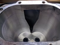
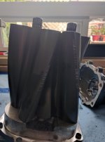
Could use some help or more like advise. Started tearing down my supercharger when it sounded like the bearings might be toast. When I opened it found this...

I would assume its salvageable, but what do you think?
 

Attachments

  • IMG_20160612_161316.jpg
    IMG_20160612_161316.jpg
    124.9 KB · Views: 3,187
  • IMG_20160612_161223.jpg
    IMG_20160612_161223.jpg
    113 KB · Views: 3,183
Yea I figured I was going to be loosing out on some pressure. I would assume there is no real way to save the housing at this stage?

That is probably a question for one of the more professional refurbishing companies.

Can anyone tell me the size of the "T" Fitting I need? Or where I can get one?

Talking about the T fitting between the s/c housing and fuel pressure regulator for the boost gauge hose? Good question - I am looking for one now so I can replace my current broken hose.
 
Yea I figured I was going to be loosing out on some pressure. I would assume there is no real way to save the housing at this stage?


My SC was exactly the same when I tore it apart. I replaced the whole rotor assembly with a new one though. I'm still getting 7.5psi at WOT and its working fine.
 

Members online

Forum statistics

Threads
278,315
Messages
3,554,102
Members
248,016
Latest member
Advally Service

Trending content

Back
Top