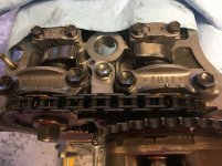
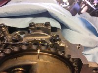
Timing chain cover and changing valve lifter on 1GR-FE

I broke the plastic sliders on both upper tensioners during disassembly w/ my impact gun as the side chain slapped them. If your impact gun is a pneumatic, get the biggest inside diameter hose you can attach to your compressor...air volume is what makes the gun work harder.

For resting the wrench holding the cam stationary, I placed a 2x4 on top of the rags covering the intake cam to avoid damage.
 
I broke the plastic sliders on both upper tensioners during disassembly w/ my impact gun as the side chain slapped them. If your impact gun is a pneumatic, get the biggest inside diameter hose you can attach to your compressor...air volume is what makes the gun work harder.

For resting the wrench holding the cam stationary, I placed a 2x4 on top of the rags covering the intake cam to avoid damage.

Re plastic sliders - I assume the only option is to replace the entire tensioner? Used Milwaukee 18V impact driver. But I’m gonna buy a compressor I think, too many times I’ve had to use brute force to undo things and ended up breaking stuff in the process (including myself!!)
 
Re plastic sliders - I assume the only option is to replace the entire tensioner? Used Milwaukee 18V impact driver. But I’m gonna buy a compressor I think, too many times I’ve had to use brute force to undo things and ended up breaking stuff in the process (including myself!!)

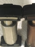
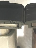
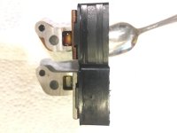
Yup, entire tensioner. And watch out for aftermarket ones, I lost 2 weeks fighting a Cloyes tensioner whose lower pad was slightly wider than factory and was making a clicking noise as the timing chain pins bumped into it. See pics of it next to the factory one.
 

Attachments

  • upper_tensioner_aftermarket_3.jpg
    upper_tensioner_aftermarket_3.jpg
    39.4 KB · Views: 730
  • upper_tensioner_aftermarket_2.jpg
    upper_tensioner_aftermarket_2.jpg
    37.9 KB · Views: 681
  • upper_tensioner_aftermarket.jpg
    upper_tensioner_aftermarket.jpg
    52 KB · Views: 741
Last edited:
Yup, entire tensioner. And watch out for aftermarket ones, I lost 2 weeks fighting a Cloyes tensioner whose lower pad was slightly wider than factory and was making a clicking noise as the timing chain pins bumped into it. See pics of it next to the factory one.

Gosh, that looks horrible. I saw Cloyes on RockAuto and was wondering what in the world brand that was. Have now stumbled on megazip.net which seems to have stock of everything I need (RockAuto seem to be missing a number of critical seals/o-rings) so I think I'll get it all genuine from there.
 
Gosh, that looks horrible. I saw Cloyes on RockAuto and was wondering what in the world brand that was. Have now stumbled on megazip.net which seems to have stock of everything I need (RockAuto seem to be missing a number of critical seals/o-rings) so I think I'll get it all genuine from there.

Cloyes has a very solid reputation in the Ford/Chevy/Dodge marketplace, but this thing was a re-boxed Taiwan knockoff.
 
Hi all

I am putting this back together at last. When putting the camshaft timing sprockets on, I misaligned the intake sprocket so it wasn’t sitting on the dowel pin (more info later) and started tightening before realising it wasn’t right. See pic:

https://i.imgur.com/GngeLWE.jpg

There is 2mm still protruding from camshaft. Should this be sufficient? Not sure what the spec is and I haven’t taken the other side to compare with off as no need to (no lifters needed changing). Exhaust cam has 3mm of dowel pin protruding so I’m guessing I lost 1mm.

Next question... this is how the cams are sitting:

https://i.imgur.com/AmGdCHU.jpg

Is this right? Haynes says front intake lobe on the left side intake should be pointing towards 7 oclock, and front on the exhaust pointing up, which they are. However in this configuration, the pin is at about 3 o’clock (this is how I screwed up)... on the inner cam sprocket there are two sets of dots, a single and a double. I originally had the yellow marks on the chain line up with single dot but it’s impossible in this way to make everything align properly. Should it instead align with the double dots? See below:

https://i.imgur.com/hfwHLnf.jpg

When installed, this is how it looks:

https://i.imgur.com/EmHeQLH.jpg

https://i.imgur.com/A1XshWg.jpg

https://i.imgur.com/EnmLKOg.jpg

So, before I keep going, does this look right, and is 2mm on the dowel pin still likely to be sufficient? The sprocket feels solid on the camshaft and when it’s torqued I guess it’s not going anywhere. If this is an issue though, what’s the best way to fix it?
 
Another thing I’ve just noticed. With the inner timing chain sprocket, it appears there is a crack in each side of the inner collar. See pics below. It doesn’t appear to extend through the collar though. Are these cracks or just part of how they get the collar in at install? Replace?

At 12 o’clock:
https://i.imgur.com/YFSs5xD.jpg

Other side:
https://i.imgur.com/HqHjGBc.jpg

Side view showing no crack inside collar (crack just past 3 o’clock in this pic):
https://i.imgur.com/yyb7MIg.jpg
 
On the camshaft pin, I took this to a local shop who rebuild engines. They said there is plenty of grab left when the camshaft meets the sprocket and that it’s only a guide pin anyway, once torqued up the pin serves no purpose. So that’s good. And there really is only one way the sprockets can go on the camshafts. Just wish the Haynes guide explained why the intake sprocket has two sets of dots on the back. I can only assume that whether it’s on bank 1 or bank 2 affects the positioning, and it’s the same part number for both banks.

If anyone has thoughts on those tiny cracks in the centre sprocket that would be amazing.

Thanks
 
Another thing I’ve just noticed. With the inner timing chain sprocket, it appears there is a crack in each side of the inner collar. See pics below. It doesn’t appear to extend through the collar though. Are these cracks or just part of how they get the collar in at install? Replace?

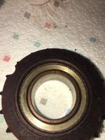
I just grabbed the factory idler sprocket that came out of mine, and snapped a pic showing that same fissure in what appears to be the same location as shown. The same fissure is present on the opposite side of the sprocket, but barely visible...I had to use a magnifying glass and then verify by dragging my fingernail across it to feel it catch. I'd feel safe saying this is the design, not a crack or indication of failure.

I replaced this during my timing chain project, and didn't notice any such fissure in the new Toyota part...but admittedly I didn't examine it this closely.

The cost was pretty low from an online Toyota dealer if you feel like replacing it.
 

Attachments

  • 4runner_idler_sprocket_1.jpg
    4runner_idler_sprocket_1.jpg
    130 KB · Views: 684
Last edited:
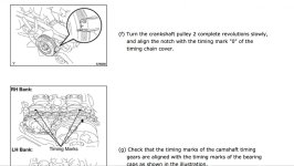
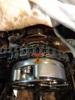
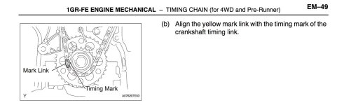
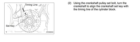
Good research and great find. Back to your question on the timing marks, the attached diagram shows the intake sprocket timing mark positions with the crank at zero mark. Also attached diagrams for the crank marks showing the position of the chain marked link on the sprocket, and the block casting timing marks. And finally, a pic of my bank 1 showing the staggered positions of the chain marked links on the main chain (offset to 1 o'clock) and the exhaust chain (12 o'clock). Hope these help.

Found this:

1353031011 Genuine Toyota SPROCKET ASSY, IDLE 13530-31011 | eBay

Same “crack” appears in brand new one if you zoom in. I assume the reason why the inner collar looks perfectly smooth on mine is 15 years of heat and rotation which has worn down and welded that crack to a perfect seal. So. I will leave it and hope for the best :) Like always though, thanks for the help. This forum is full of very helpful people!
 

Attachments

  • cam_timing.jpg
    cam_timing.jpg
    116.3 KB · Views: 3,117
  • 4Runner_bank1_intake.jpg
    4Runner_bank1_intake.jpg
    114.2 KB · Views: 4,145
  • manual_crank_marks.jpg
    manual_crank_marks.jpg
    96 KB · Views: 1,748
  • manual_crank_marks_2.jpg
    manual_crank_marks_2.jpg
    85.3 KB · Views: 1,778
Found this:

1353031011 Genuine Toyota SPROCKET ASSY, IDLE 13530-31011 | eBay

Same “crack” appears in brand new one if you zoom in. I assume the reason why the inner collar looks perfectly smooth on mine is 15 years of heat and rotation which has worn down and welded that crack to a perfect seal. So. I will leave it and hope for the best :) Like always though, thanks for the help. This forum is full of very helpful people!

I am going through this as I complete my engine build.

I don't think its a crack. I think its a bronze split bushing. Same type of bushing type used for the wrist pins. I also bought the Cloyes kit that came with the idler sprocket but not the sprocket assembly. which sucks because I cant figure out how to separate the assembly. You guts posted some good pictures, take a look at how its assembled it doesn't appear it can be disassembled. So you end up with a new sprocket that cant be used.

Also had a problem with one of the Cloyes tensioners. The housing appear to be slightly miss aligned. The housing has a bolt hole and a alignment pin hole. My assembly is slightly cocked where the pads don't align with the chain.
Fun project, good luck.
I have the FSM if you need some specific instructions on the timing mark.
 
waypoint has some good info. This is my view today.
 

Attachments

  • IMG_3935 a.jpg
    IMG_3935 a.jpg
    128.3 KB · Views: 2,217
  • IMG_3934a.jpg
    IMG_3934a.jpg
    117.7 KB · Views: 2,276
Thanks again for the replies, good to know I'm on the right track.

Next problem/question... I have all the chains/sprockets back on and have been turning the crank to make sure it stays in time. Good news: It does. Probably 10+ rotations now, all the dots stay in alignment. HOWEVER, part way through each turn, at the same point on the turn, slack is introduced around the idler pulley. It then tightens up again. It's not a stretched part of the chain as the chain is gradually shifting its position on each rotation obviously, and the slack introduces itself at the exact same point of the crank/cams turning each time.

Video below. Any thoughts as to if this is normal or if it's an issue? I didn't video this but the tension on tensioner 1 is variable - it goes in and out a little as the chain is going around.

Video of slack in chain

If you look at this video:

YouTube

At 1:27:47 he starts rotating the crank and you can see the slack suddenly introduce in the idler sprocket. Can also see the no. 1 tensioner being quite variable and coming and going on the chain guide there as he turns it, which is what I also see. So I'm HOPING I'm ok? It's just a lot more slack than I imagined around that idler sprocket.

EDIT: Just did more experimenting. It seems like, at the point slack is introduced, I can slightly turn the intake cam on each side. Not much, but enough to move the slack to either side of the bank in question (tensioner side or idler sprocket side in this video). When the chain is tight, that movement doesn't exist. Is it just that, at some point, the intake and exhaust cams are "balanced" and so they get a tiny bit of slack which introduces slack into the main chain? Is this an issue? Video below:

Video of minor cam movement when slack appears

EDIT 2: Seems to happen in this video too at about 18:32. Must be normal!

YouTube

 
Last edited:
Another question... are these DEFINITELY threaded studs?

Studs - Album on Imgur

Just put a 6mm socket on the end and have a few gentle twists and didn’t budge. Don’t want to snap them out, that would be a horrible end to the project. Definitely feel pretty lightweight though. I like your idea of having them out the way to plonk the timing cover straight on the sump though, rather than slide it on with the sealant squishing everywhere while I do it.
 
Another question... are these DEFINITELY threaded studs?

Studs - Album on Imgur

Just put a 6mm socket on the end and have a few gentle twists and didn’t budge. Don’t want to snap them out, that would be a horrible end to the project. Definitely feel pretty lightweight though. I like your idea of having them out the way to plonk the timing cover straight on the sump though, rather than slide it on with the sealant squishing everywhere while I do it.

They are threaded studs, but are Torx not hex...you'll want a proper Torx socket to remove and reinstall them.

Removing these and leaving the crank main seal out of the timing cover helps during re-installation of the timing cover. You don't want to damage or dislodge the oil pump pickup o-ring, and aligning the oil pump to the crank gear is tough to do even following the shop manual.
 
Don't take my word on the slack, but the tensioner pin is oil pressure based, not a high pressure charged cylinder like many other cars might have for a rubber belt and won't be pushing onto the chain very hard unless the engine is running.
I used the AutoZone guides when installing mine and checked it 10 times before bolting it all back together.
That first startup when it is together is always unnerving.
 
Don't take my word on the slack, but the tensioner pin is oil pressure based, not a high pressure charged cylinder like many other cars might have for a rubber belt and won't be pushing onto the chain very hard unless the engine is running.
I used the AutoZone guides when installing mine and checked it 10 times before bolting it all back together.
That first startup when it is together is always unnerving.

Thanks, yeah I’ve gathered the oil pressure will fix the slack from a few things I’ve found. And yes. I am crapping myself about first startup. Afraid I’ve dropped something in the sump or will screw up a seal or blah blah blah, imagining all the things that could go wrong. Oh well. Only a car right??
 
Thanks, yeah I’ve gathered the oil pressure will fix the slack from a few things I’ve found. And yes. I am crapping myself about first startup. Afraid I’ve dropped something in the sump or will screw up a seal or blah blah blah, imagining all the things that could go wrong. Oh well. Only a car right??

Remove the fuel pump relay or fuse before that first startup. Spin the engine on the starter until the oil pressure light goes out, and leave it spinning for a few seconds after this. Pressurizes the chain tensioners nicely and makes for a quiet initial startup.

Pre-lube the key areas before you install the timing cover and valve covers. Apply break-in lube to the chain contact surfaces...sprocket teeth, tensioner pads, guides. Dribble oil onto the camshaft lobes so they're not dry during startup. Dribble oil onto the chains.
 

Members online

Forum statistics

Threads
278,316
Messages
3,554,120
Members
248,016
Latest member
Advally Service

Trending content

Back
Top