What Am I Doing Wrong - Aftermarket Radio Edition

tbst

New member
I am trying to install a Kenwood stereo (KDC-MP345U). I have installed the radio temporarily and the radio and speakers work. However, the power antenna will not actuate.

I have connected the standard stereo wiring harness to the aftermarket harness that connects to the OEM wiring harness from the radio.

I pulled the factory amp out and cut the wires as shown below. What is shown are the blue and red wires that were connected to the factory amp. (The ones I hastily cut.)

71015689.jpg~original


After I made all the connections with the standard stereo harness using the aftermarket harness I bought, the only colors that are not in use on the standard stereo harness are solid blue and blue with stripe. (Along with another one that says mute on the tag, I think irrelevant.) They are shown below.

5dbb2445.jpg~original


The only one that is not used on the aftermarket harness I bought is blue and orange. They are shown below.

a66321b7.jpg~original


What I have done so far is connect the blue from the aftermarket harness to the blue on the stereo. Nothing.

Connect the blue directly from the stereo to the blue that I cut off the amp. Nothing.

Randomly connect other wires. (Probably not the best idea, hence details not needed).

So which wire specifically do I need to connect to get it to actuate the power antenna, if you would be so kind?

Remember, I am slow. So the more detail the better.

Thanks guys.


(2001 T4R SR5 4wd, btw.)
 
Register to hide this ad
Was the power antenna working before?

On the aftermarket harness, the Orange and white wire isn't needed.

The blue wire should be the low draw wire that powers the amp (or the antenna). Sounds to me like you've got the right wire, but I think you've maybe got a seized antenna?
 
This should help you out some. Page 196 in the FSM.

Ahhh, any time a see an op amp I become immediately sick and have to throw up all over my computer. (It gets costly.)

On a serious not, two EE classes apparently didn't teach me much. What is the block on the center of the first page representing in terms of tangible harness?
 
one thing you are doing wrong is using twisted wire + electrical tape instead of simple crimps or quick-disconnect connectors.
 
one thing you are doing wrong is using twisted wire + electrical tape instead of simple crimps or quick-disconnect connectors.

There are crimps under the electrical tape. The first picture you can see the crimps that haven't been taped.

Any ideas on the actual antenna issue?
 
read write ups on here about adding switches to the power atenna, might try searching for those threads. Might be helpful figuring it out. If you could add a bypass switch that allows you to choose when you want it up or down, might solve your problem. If not sorry for wasting your time :)
 
Found this going to the Kenwood manual. I have already done this. I know the radio is connected to the ignition switch already or it would not turn off and on with the car.

Keeping thread updated for future people who stuble upon it.

KenwoodManual.jpg~original
 
I just put my KDC-X494 in about a month ago and ran into this exact situation.

There are TWO different kinds of harnesses for Kenwood radios. The 'cheaper' version is for the non-Excelon Kenwood radios, and has about 3 or 4 fewer wires, with one of those missing wires being the power antenna.

However, the more expensive one for the Excelons DOES have the correct wires. tbst, any local sound shop should know this, and should have the correct harness.

Once I got the correct harness for my radio, install went fantastic, and my antenna works like a charm, goes up and down at the proper times. :)
 
I just put my KDC-X494 in about a month ago and ran into this exact situation.

There are TWO different kinds of harnesses for Kenwood radios. The 'cheaper' version is for the non-Excelon Kenwood radios, and has about 3 or 4 fewer wires, with one of those missing wires being the power antenna.

However, the more expensive one for the Excelons DOES have the correct wires. tbst, any local sound shop should know this, and should have the correct harness.

Once I got the correct harness for my radio, install went fantastic, and my antenna works like a charm, goes up and down at the proper times. :)

Hmm, interesting.

Just to clarify, the cheaper harness that you had, starting with the one that is connected to the actual Kenwood, did it have the blue/white wire running out of it?

And then with the wire connection that connects to the actual car harness, did it have the blue wire running out of it?

That is what I have and I would prefer to not be a noob if I have to run to an audio place. :)
 
Hmm, interesting.

Just to clarify, the cheaper harness that you had, starting with the one that is connected to the actual Kenwood, did it have the blue/white wire running out of it?

Aaaah, I'm glad you brought this up; I realize I wasn't clear enough in my last post. My apologies.

It was actually the RADIO harness that I had to 'repurchase.' I originally needed BOTH the 'vehicle adapter' (the one that plugs into the vehicle's harness) and the 'radio adapter' (the one that plugs into the back of the radio).

The 'vehicle adapter' had the blue/white power antenna wire on it ; however, the radio adapter did NOT.

I called Crutchfield @ that point (where I got my Kenwood from) and very quickly I realized my radio adapter was missing more than a few wires. The guy did mention that he thought there were two different harnesses.

So I called the local audio shop up (where I purchased both adapters) and they said "OH. You didn't tell us you had an Excelon." (Which I actually HAD told them, but anyways.)

Turns out the 'cheaper' Kenwood radio harnesses don't have those wires, and more expensive ones (for Kenwood radios > $150 or so, and all Excelons) DO have the correct wires.

SO, in short, you should be able to run to any audio shop and ask for - and receive - a Kenwood Excelon radio harness. If they look at you like you're an idiot, shop around. If you want, I can call my local shop tomorrow and get the correct part # for the one I got.
 
Here's the link to the actual Kenwood adapter, if you want it.

E30-6798-05

You may check with them to see if it has the correct wires. I *believe* mine was made either by Best Kits or Metra.
 
My Experience...

I put in an aftermarket stereo in my 1998 4Runner, and had to contend with the factory power antenna relay module.

Aftermarket power antennas will have a constant power and ground running to them, and also a blue "sense" wire - similar to how aftermarket amplifier wiring is. The antenna will go up when voltage is applied to the sense wire, and go back down when voltage is not present.

However the stock Toyota power antenna simply has two wires running to it, and the relay module controls what wire gets voltage and what one gets ground depending on the up or down action required. For example, the DC motor that drives the antenna will go one direction if power is on one lead, but reverse what wire gets power, and the motor will go in the opposite direction. This is a good way to test the power antenna itself, just do not leave power connected to it for more than a few seconds or you will burn out the antenna.

The relay module has electronic timing circuits built in to automatically shut off the power to the antenna motor after a predetermined amount of time has elapsed for an "up" or "down" travel time. This keeps the antenna from getting damaged.

If you have a power antenna relay module in your truck, the aftermarket stereo's power antenna wire will have to be connected to the correct wire (pin) on the relay module, and not the antenna itself.

The relay module essentially works the same way as an aftermarket antenna or amplifier would.

For example if you turn on your stereo to the tuner or FM/AM input, it will apply positive 12vDC to the head unit's power antenna out wire - if this is connected to the correct relay module wire, the relay module responds by sending voltage to the stock antenna and it goes up, shutting off automatically after a couple seconds.

Change your stereo from the tuner to something else, or turn it off completely, and the head unit's power antenna wire will no longer have voltage - thus the relay module will switch what antenna wire gets voltage, and as a result, the antenna will lower and shut off a few seconds later.

Being the circuit board level tech geek that I am, I removed my relay module, and put it on my tech bench with a 12v power supply to test the various pin outs on the mass connector. It is pretty easy to spot the constant 12v and GND connections out of all the wires that go into the relay module - the are the largest in diameter, and the darker color is usually the GND. You would also know what wires are the output to the antenna - they would have the same color and stripe as the only two wires that connect to the antenna mounted in the fender.

While giving the relay module constant power and ground, I used a DMM to monitor any voltage between the output pins. Then all that was required was to (one pin at a time) apply 12v to the remaining pins and watch the DMM to see when either positive or negative DC voltage was present. If you do not have a voltage meter, a simple 12v light bulb will work connected to the output pins. It won't show if you have positive or negative voltage, but it will light up when any power is present.

Once you find the right pin, you will hear the relay module "click" indicating that it has activated, and the DMM will show 12vDC voltage (your light will turn on). Leave that pin connected to power and a few seconds later you will hear another click indicating the relay has turned off - the DMM will show 0volts (the light will turn off). Once you remove power from that pin, the relay will click, the DMM will read the opposite 12vDC voltage, and a few seconds later another click indicating the relay has shut off.

Reviewing what I have typed here, I see that it would have been way easier to simply have told you what wire color I connected my head unit's output to, but there is no way to tell if your wiring has the same color code as mine did...

The Toyota factory service manuals did not help, as there was no schematic within telling me what wire color did this function - and an online search for the relay module's part number did not turn up any internal schematics either...so I had to spend some time at the tech bench to find out my answer...

Hope this helps in some way...
 
If you have a power antenna relay module in your truck, the aftermarket stereo's power antenna wire will have to be connected to the correct wire (pin) on the relay module, and not the antenna itself.

Can you tell me why this is necessary?

I'm not saying that it's not necessary, at least not on the 4Runner you have; but I've got a 2000 4runner SR5 4x4, and he's got a year newer, which is not appreciably different. And all I needed to do was get the correct radio wiring harness. (There's a 12-wire and a 16-wire harness, I believe.)

I'm like you - former ET in the Navy, and current IT for the last 16 years - and if I'd had to engineer a solution I could/would have. However, in my particular case, all that was needed was the correct wiring harness - and there ARE 2 different wiring harnesses for Kenwoods. (Whereas with, say, Alpine, there's one, count 'em one, that I know of. LOL Leaves little to confusion.)
 
All factory wiring blows...

To start with, even those that know me best think that I over engineer just about everything I come in contact with... :)

But I had ZERO intentions on using any part of my factory power or stereo wiring when I set out to put my dual zone A/V system within my 4Runner...

I ran dedicated power and ground 2/0 high-strand count copper wire from my optima battery through the fire wall to distribution blocks and then to circuit breakers. From there the circuits went to noise isolators for each part of my power distribution system - one part for each zone, and a third for all the additional 12v accessory outlets - even replacing the factory cigarette lighter (and the outlet in the hatch area) wires with 12gauge...

A very detailed, and even longer story cut much shorter...

The only factory system, and related wiring, I wanted to re-use was the power antenna. So unfortunately, I was unable to use a simple aftermarket harness adapter, as I would have nothing to plug it into.

This meant backwards engineering the factory relay module...and for a time I had already began to sketch out my own timing circuit to use in place of the Toyota one...but figured, they already had a proven design, why not just use theirs...?

There is no kill like overkill... :)
 
Here's the link to the actual Kenwood adapter, if you want it.

E30-6798-05

You may check with them to see if it has the correct wires. I *believe* mine was made either by Best Kits or Metra.

So the harness that came with the head unit did not have the right harness to connect to the power antenna?

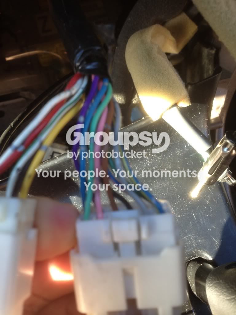
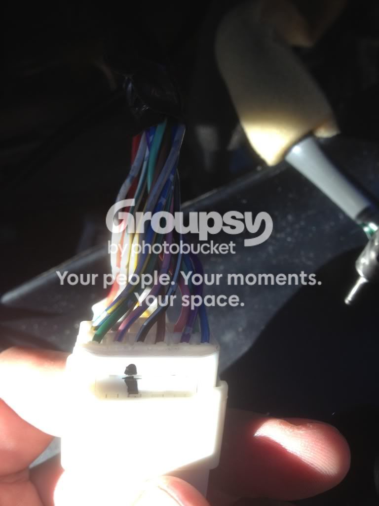
Here are some pictures of the harness I have. I checked out the link but couldn't get any good images of the actual wire coloring? Is this the one you used to have?

2d9c42f0.jpg~original


The other side.

3926be95.jpg~original


Aftermarket power antennas will have a constant power and ground running to them, and also a blue "sense" wire - similar to how aftermarket amplifier wiring is. The antenna will go up when voltage is applied to the sense wire, and go back down when voltage is not present.

However the stock Toyota power antenna simply has two wires running to it, and the relay module controls what wire gets voltage and what one gets ground depending on the up or down action required. For example, the DC motor that drives the antenna will go one direction if power is on one lead, but reverse what wire gets power, and the motor will go in the opposite direction. This is a good way to test the power antenna itself, just do not leave power connected to it for more than a few seconds or you will burn out the antenna.

The relay module has electronic timing circuits built in to automatically shut off the power to the antenna motor after a predetermined amount of time has elapsed for an "up" or "down" travel time. This keeps the antenna from getting damaged.

If you have a power antenna relay module in your truck, the aftermarket stereo's power antenna wire will have to be connected to the correct wire (pin) on the relay module, and not the antenna itself.

The relay module essentially works the same way as an aftermarket antenna or amplifier would.


Being the circuit board level tech geek that I am, I removed my relay module, and put it on my tech bench with a 12v power supply to test the various pin outs on the mass connector. It is pretty easy to spot the constant 12v and GND connections out of all the wires that go into the relay module - the are the largest in diameter, and the darker color is usually the GND. You would also know what wires are the output to the antenna - they would have the same color and stripe as the only two wires that connect to the antenna mounted in the fender.

Reviewing what I have typed here, I see that it would have been way easier to simply have told you what wire color I connected my head unit's output to, but there is no way to tell if your wiring has the same color code as mine did...


Hope this helps in some way...

Attached above are some pictures of the actual harness I have. Maybe you can recollect about the factory harness? The pictures that I have that are not above are below.

I am lost. I just don't get what wires?

Where was the module itself?

Does this loop have to do with something? It was mentioned in some threads where people put in a button. It seems evil.

c3ff9997.jpg~original


Factory harness top.

08bc8a3c.jpg~original


Factory harness bottom.

3e21a76d.jpg~original


Aftermarket harness top.

10dd8f78.jpg~original


Aftermarket harness bottom.

258f6213.jpg~original


Thanks so far!
 

Members online

Forum statistics

Threads
278,316
Messages
3,554,120
Members
248,016
Latest member
Advally Service

Trending content

Back
Top