What Am I Doing Wrong - Aftermarket Radio Edition

I ran dedicated power and ground 2/0 high-strand count copper wire from my optima battery through the fire wall to distribution blocks and then to circuit breakers. From there the circuits went to noise isolators for each part of my power distribution system - one part for each zone, and a third for all the additional 12v accessory outlets - even replacing the factory cigarette lighter (and the outlet in the hatch area) wires with 12gauge...

This is way overkill!

I ran my own ground and power through the firewall for my Alpine head unit and I clipped all the speaker wires since I have a 4-channel amp under the drivers seat. I also ran new 14G speaker wire to each speaker.

In all it took me < 1 hr to install the head unit, not counting the speaker wire.
 
Relay Module

Kung is essentially correct...there really is no need to science things out to the extent that I did if you are re-using original factory wiring...

There was (somewhere) in the factory wiring a wire that goes to the correct pin on your factory relay module already... The purpose of the wiring adapter is to tap into that wire (among others) without cutting any of the original wiring within the truck. The harness should have come with a diagram with a color code chart of its own that you will have to relate to the color code chart of the head unit you are attempting to put in - including the power antenna connection.

The trick is to not only have the correct wiring harness, but also to connect the new stereo's wiring to the correct wires of the aftermarket harness.

Contrary to what others have posed about crimp connectors - they suck too... Learn how to make a proper mechanical connection with the bare wire ends and thoroughly solder them together... I re-wired an entire ambulance emergency wires and center console controls... I can't tell you how many crimp connections I found that were corroded or simply not making an electrical connection at all...

The pain in the ass part is if they changed the module wiring at all from my 1998 to your model year. One would think that it would be the same...but I have learned never to assume anything so simple...

Those two wires you have unaccounted for (Red and Blue) could be the constant power and ground to a relay module, if they are, the antenna will never see any juice without these connected...there is no way to tell without a schematic diagram - nor do I suggest that you simply "hook them up" in some way to "check"... Do you know what these were connected to prior to cutting them?

As far as the location for this module, mine was directly underneath the radio location, on the drivers side of the dash opening - about the size of a deck of cards. If memory serves, the factory amplifier was located directly behind it - centered inside the dash opening.

Hope this helps...
 
So the harness that came with the head unit did not have the right harness to connect to the power antenna?

Remember that I mentioned (at least I believe I did) that I had to buy *BOTH* harnesses - the original radio harness was lost or something, so I had to purchase an aftermarket radio harness. THAT one did not have the correct wiring.

This being said....I may have my colors mixed up because you have a wire (blue/white) I didn't think you have/had. Lemme go do a bit of nosing around and I'll get back to you.
 
Remember that I mentioned (at least I believe I did) that I had to buy *BOTH* harnesses - the original radio harness was lost or something, so I had to purchase an aftermarket radio harness. THAT one did not have the correct wiring.

This being said....I may have my colors mixed up because you have a wire (blue/white) I didn't think you have/had. Lemme go do a bit of nosing around and I'll get back to you.

Excellent. The harness I have for the actual radio is the one that came with the Kenwood originally.

I had to put it all back together today, have to be able to drive it here.

However, if we get this figured out I will tear it back apart, now that I know how is it is to do!

Let me know. :)
 
Ok, I posted the pinout that goes for my current one. Don't pay much attention to the colors, though, because the important thing is that functions are matched up. If I remember correctly, the 'power antenna' color on the radio harness does not match the 'power antenna' color on the vehicle harness.

In any event, let me know which functions you DON'T have. (E.g., whatever wires DON'T match up.)

Accessory 12 Volt - grey
Constant 12 Volt - blue/yellow
Chassis Ground - brown
Power Antenna - black/white
Remote - pink/blue
Illumination - green
Dimmer 15 WT/GN

Left Front Spkr + - pink
Left Front Spkr - - violet
Right Front Spkr + - light green
Right Front Spkr - blue
Left Rear Spkr + - black
Left Rear Spkr - - yellow
Right Rear Spkr + - red
Right Rear Spkr - - white
 
Do you know what these were connected to prior to cutting them?

These two were the wires that were connected to the amplifier. There was some talk in other threads that the red one was the "remote" wire for the amp, however this doesn't make sense, IMO because the amp had the factory harnesses plugged into it, so it would have an ignition wire. What do you think? Do you remember?

As far as the location for this module, mine was directly underneath the radio location, on the drivers side of the dash opening - about the size of a deck of cards. If memory serves, the factory amplifier was located directly behind it - centered inside the dash opening.

Yeah, when I connected the blue/white wire to the blue wire that was connection to the amp, as mentioned above, that box did some clicking. However, nothing happened.

And to clarify, the antenna worked yesterday.
 
Ok, I actually went and looked up your head unit on Kenwood's site. The link to the PDF is here:

http://www.kenwoodusa.com/UserFiles/File/UnitedStates/Consumer/Manuals/kdcmp345u.pdf

It lists the pinout as follows:

Front left spkr - white (+) white/black (-)
Front right spkr - gray (+) gray/black (-)
Rear left spkr - green (+) green/black (-)
Rear right spkr - purple (+) purple/black (-)

Power control/antenna motor control - blue/white
Mute Control - brown
Ignition - red
Battery wire - yellow
Ground - black

Bluntly put, as long as your radio harness has these wires, and as long as the vehicle harness (by that I mean the harness you plug into your vehicle's harness, and solder/crimp the ends to your radio harness) also has the same wire (a wire for your antenna motor control), there's no reason at all that it SHOULDN'T work.
 
Bluntly put, as long as your radio harness has these wires, and as long as the vehicle harness (by that I mean the harness you plug into your vehicle's harness, and solder/crimp the ends to your radio harness) also has the same wire (a wire for your antenna motor control), there's no reason at all that it SHOULDN'T work.

Yeah, I checked that PDF out earlier.

Yeah, I wish I knew the reason why it doesn't work.

I have crimped the blue/white from the Kenwood to the wiring harness for the OEM connection. Nothing.

Connected the blue/white from the Kenwood to the blue that came off of the amplifier. Nothing.

Here is a question for Kung and all, does the red that comes off the factory amplifier power the antenna? Do I need to three way that in with my antenna and then connect the blue to the blue/white from the head unit?

Pretty sure I did ^^ but I guess it is worth a shot again I guess.

I guess my question is what is the red that goes into the amp? Remote wire or power for the antenna? I have read conflicting things in old thread.

Damnit, in general.

Thanks so far Kung.
 
I have crimped the blue/white from the Kenwood to the wiring harness for the OEM connection. Nothing.

Connected the blue/white from the Kenwood to the blue that came off of the amplifier. Nothing.

Here is a question for Kung and all, does the red that comes off the factory amplifier power the antenna? Do I need to three way that in with my antenna and then connect the blue to the blue/white from the head unit?

In short, nope. The *ONLY* thing you should have to do at ALL is crimp/solder the 'power antenna' wires together. That's it. (BTW, I never crimp anything together. Not that it's worthless, but solder is simply more permanent and you get a better connection, IMHO.)

I guess my question is what is the red that goes into the amp? Remote wire or power for the antenna? I have read conflicting things in old thread.

That I don't know, but I DO know that there's no requirement to rewire anything. I see what Dewyz1100 is doing, and one *can* do that, but is it a requirement? Obviously not, or else my antenna wouldn't go up and down when I turned my Kenwood KDC-X494 on/off, or switched to and from the radio.

IMHO, either something's shorted out, you don't have (or you didn't have) the best connection between your power antenna wire leads, or something else is going on that I can't think about right now.

(My apologies for being fuzzy-headed; I busted my butt @ my military unit today after an APFT, and then soon as I got home, I got to complete an assignment for Systems Analysis and Design II. Trust me...you don't want to take that course if you don't have to. LOL)

Also - I didn't quite realize from the outset that you'd already tried all this stuff; I sort of thought it was a "Hey I dunno how to do this, how do I do this?" thread. I didn't realize you'd had all the instructions, followed them to the letter, evidently HAD the correct harness, etc., and was posting AFTER that point. I guess I'm fuzzier than I thought.
 
Last edited:
Also - I didn't quite realize from the outset that you'd already tried all this stuff; I sort of thought it was a "Hey I dunno how to do this, how do I do this?" thread. I didn't realize you'd had all the instructions, followed them to the letter, evidently HAD the correct harness, etc., and was posting AFTER that point. I guess I'm fuzzier than I thought.

No problem.

Been trying to fix this problem with the headunit and work on reservoir simulations for a applied reservoir engineering class, all night.

Solver function in Excel must be related to the power antenna in the Runner. Both are garbage, to me, at this point.

I am going to look into why that wire loops. I think that is something messed up.

Also, I am going to look into what the red wire I cut is for. And then maybe three way that with the red on the harness and connect the blue.

Nothing to lose.
 
Sure enough...

I wish you the best of luck on this headache...

It is stories, and previous experiences like this that make me do what I do when I tackle a project. People end up tearing their hair out over something that was supposed to be as simple as hooking up an adapter to a factory harness...

I guess I am more interested in what things can do, more than what they are designed to do... For me, it is just easier to start from scratch and design it all, modifying the system design as needed once I am in the thick of it... That way there is no confusion of what wire is what, and "where does that one go?"...

Plus, this way I can make improvements along the way, and if I find some system like the OEM power antenna that I want to use, I can science it out enough to get it to work with what I have in my design...

All this is no consolation, or help, for your current predicament...sorry...

On a more specific note... That power antenna relay has several more "control" and "sense" wires running in and out of it... Again, having never seen any OEM schematic, or pin out diagram for the module, it is hard to say for sure if there is anything else that is preventing your antenna from working the way it should...

This is why I put it on the test bench. I knew that if I found out what pins required constant power/ground, and what pins were the outputs to the antenna itself, all I needed was to find the other pin that required voltage to trigger the module to do what I wanted it to...

I knew (if I had to) I could cut all the rest and know that the antenna would go up (or down) when my new stereo told it to... I did not care about any other OEM control sensor or timing circuit having a say in my antenna usage...in fact, I wired the entire A/V system to direct voltage (with circuit breakers that could be manually tripped and reset) so I did not even have to leave the key in the ignition to jam tunes anywhere...

If I had the time, and a spare module, I would create a tech bench write-up worthy of a sticky... Alas, I do not... :(

Good luck young grasshopper... :)
 
Last edited:
Just because I like to close threads.

Figured out the solution today.

Connect the blue wire to the remote wire that comes out of the head unit. Connect the red wire to a power source, the yellow line that comes out of the factory harness works well.

What happens? Antenna goes up when Kenwood is on any mode other than standby.

I would recommend putting in a with a aftermarket unit. As the remote wire will put out signal anytime it is being used because it needs to be on for amps. Having the antenna up all the time is not necessary.

Either way, resolved.
 
Just because I like to close threads.

Figured out the solution today.

Connect the blue wire to the remote wire that comes out of the head unit. Connect the red wire to a power source, the yellow line that comes out of the factory harness works well.

What happens? Antenna goes up when Kenwood is on any mode other than standby.

I would recommend putting in a with a aftermarket unit. As the remote wire will put out signal anytime it is being used because it needs to be on for amps. Having the antenna up all the time is not necessary.

Either way, resolved.

Trying to put in amplified bass tube, and need to hook up to a remote wire. I also have an aftermarket Kenwood headunit and would like someone to confirm with me what wire to tap into. Reading through this thread and looking at wiring diagrams, can't figure out should I tap into gray wire coming from vehicle, or should I splice into blue/white or yellow from the head unit? (Its been awhile since i've been back there so I can't really remember whats connected to what <used aftermarket adaptor as indicated above> and power antenna does go up and down except in standby mode)Anybody care to pick a color as thats sort of where I am at the moment at least until I think about it some more.

BTW, i'll be in the dash again tomorrow and i'll try and snap some more pics to add to this thread as mine is pretty much identical to whats been described in this thread and the more info we can mash in here the better imo.

Thanks.

EDIT: Hmmm, just saw the "radio reset" thread, maybe I wanna splice into the yellow wire coming from the vehicle?
 
Last edited:
Yellow is the +. 100% sure of that. So not that one.

You need to tape the blue/white wire, the one that does not say antenna on it. It is either the blue/white wire or the blue wire. One of those two 100%.
 
Yellow is the +. 100% sure of that. So not that one.

You need to tape the blue/white wire, the one that does not say antenna on it. It is either the blue/white wire or the blue wire. One of those two 100%.

Cool tb :thumbsup: My manual looks identical to the one posted earlier, and it shows that blue/white being used for the factory amp, so that makes sense to me, but its also tied to the power antenna, and I thought that might cause it not to work when in CD mode being the ant. retracts. Maybe i'm overthinking..(thats hardly ever been the case), but thats gotta be it. I don't even remember the blue wire I don't believe. I'll have to get back in there and look around tomorrow, then it probably come back to me.
 
If you manual is exactly the same as the one posted, I would connect your amp to the "P.CONT" which will turn on your amp every time your head unit is on. Then I would connect the "ANT. CONT" wire to the blue/whatevercoloriscomingfromyourantenna and then get a wire nut and connect the antenna power, the yellow and the vehicle power together. That way your antenna only retracts and goes up when your listening to radio.
 
If you manual is exactly the same as the one posted, I would connect your amp to the "P.CONT" which will turn on your amp every time your head unit is on. Then I would connect the "ANT. CONT" wire to the blue/whatevercoloriscomingfromyourantenna and then get a wire nut and connect the antenna power, the yellow and the vehicle power together. That way your antenna only retracts and goes up when your listening to radio.

this is how everything already functions at the moment, so shouldn't I just be able to splice off the blue/white (Power Control) wire?

NOTE: Just realized that's "power control" not "power continous" , that changes how I see everything. DOH!
 
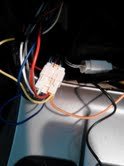
Finished the bazooka install. Unfortunately was to into just getting it done didn't get alot of pics, but did snap one of the wiring harness I used. It is the white harness indicated above, with a separate 4 point harness coming off of it for the speakers. Ended up connecting the remote wire from the amp/sub to the blue/white wire (which was being used in my setup). When you do this you have to remove the AutoOn loop that comes plugged in on the tube from the factory. Works perfectly (only on when in Tuner & CD mode, sub off in standby mode). $3.99 wire light/tester from ACE hardware found its way into my toolbox. I'll never do another electrical project w/o one.
 

Attachments

  • Kenwood wiring harness.jpg
    Kenwood wiring harness.jpg
    4.6 KB · Views: 862

Members online

Forum statistics

Threads
278,316
Messages
3,554,120
Members
248,016
Latest member
Advally Service

Trending content

Back
Top
