Which static alignment specs are directly adjustable on a stock 2wd 3rd-gen 4runner?

Status
Not open for further replies.
One spin would probably too much, if you knew for certain you were at 0, 1/2 spin per side would be more than enough. NOW the real question is how you get the Degrees™ symbol on your numbers!

:wtf:

Jeez, I feel really stupid. How do you do a half-spin? You don't put the end on upside down, do you? It's conical, right? I guess this is why I went over on my toe-ins.

Be gentle. I said I was outside my comfort zone.

alt-248= ° (Use the number pad, not the top row)

Great little site: http://usefulshortcuts.com/alt-codes/instructions-for-using-alt-Codes.php

You can do Ohms, too: Ω (Alt-234)

Here is my cheat sheet:

Degree ° Alt-248
Plus/Minus ± Alt-241
Divide ÷ Alt-247
Omega Alt 234
Dot · Alt-250
Square ² Alt-253
Cube ³ Alt-179
Cent ¢ Alt-0162
Copyright © Alt-0169
Quarter ¼ Alt-188
Half ½ Alt-0189
3/4 ¾ Alt-0190
Section § Alt-0167
Reg. ® Alt-0174
Micro µ Alt-181
Euro € Alt-0128
₠ π ΩΣΦΔ∞≈™≠♀♂
Yen ¥ Alt-0165
Pound £ Alt-0163
Pi
 
Last edited:
OK, you need to forget the Triangle

I think I will give up on the triangles but in my defense, I must say I wouldn't even think of measuring toe as triangles except that the damn spec is in degrees!
229984d1481377751-measuring-toe-home-what-triangle-does-toyota-angular-toe-specs-indicate-toyota_toe_trig_angle2.gif


Build a tire scribe and set the toe 1/16" shorter in the front than the back.

I watched a bunch of videos for how to measure toe which pretty much used a toe plate and tape measure so I'm going to try that method of measuring linear distance (and not angular degrees).

As you noted, toe is really just a smidge positive, so what you're saying is that I can set the toe to zero and then bring the front of the tire tread in about 1/16th inch with respect to the rear of the tire tread (measured as close to the centerline of the wheel as I can get).

1/16th inch on each side will give me a total toe in for the front axle of about 1/8th inch.
If that's the spec for this SUV, then I'm fine with that.

Or, find a good alignment shop that spent the 20 grand for a good imaging aligner and drive it home!

The plan that I'm forming as I type is to check caster, camber, and toe (in that order) because caster affects camber which affects toe (I'm told).

I think the camber will be relatively easy to measure because I can measure the camber with a magnetic-base level gauge which seems to have an inclinometer that has six minutes (1/10th of a degree) of accuracy.

Caster 1.7° to 3.2°
Camber -.6° to .9°
Total toe 0° to .4°

The measurement is apparently caster first, then camber, and then toe.


1. Measuring caster:

Is the caster 1.7 to 3.2 degrees easy to measure with a magnetic base digital level gauge ? [Do I place the digital level against the upper and lower ball joints?]


2. Measuring camber:

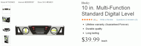
I think it will be easy to measure camber of -.6 to .9 degrees using something like a Home Depot Husky 10-inch digital level gauge with an inclinometer accurate to 1/10th of a degree (six minutes).


3. Measuring toe:

I'll give up on the angular total toe spec of 0 to .4 degrees and just measure with toe plates and a tape measure whether each front tire tread is 1/16th of an inch closer in the front than in the back (measured as high up on the tread as I can get to the centerline of the wheel).

So, I think I have a handle on how to measure camber and toe, but not yet caster.
Any suggestions for measuring caster given that I'll have a 10-inch magnetic digital level?

 

Attachments

  • husky.gif
    husky.gif
    30.2 KB · Views: 1,313
Last edited:
I think I will give up on the triangles but in my defense, I must say I wouldn't even think of measuring toe as triangles except that the damn spec is in degrees!
229984d1481377751-measuring-toe-home-what-triangle-does-toyota-angular-toe-specs-indicate-toyota_toe_trig_angle2.gif


I watched a bunch of videos for how to measure toe which pretty much used a toe plate and tape measure so I'm going to try that method of measuring linear distance (and not angular degrees).

As you noted, toe is really just a smidge positive, so what you're saying is that I can set the toe to zero and then bring the front of the tire tread in about 1/16th inch with respect to the rear of the tire tread (measured as close to the centerline of the wheel as I can get).

1/16th inch on each side will give me a total toe in for the front axle of about 1/8th inch.
If that's the spec for this SUV, then I'm fine with that.


The plan that I'm forming as I type is to check caster, camber, and toe (in that order) because caster affects camber which affects toe (I'm told).

I think the camber will be relatively easy to measure because I can measure the camber with a magnetic-base level gauge which seems to have an inclinometer that has six minutes (1/10th of a degree) of accuracy.


The measurement is apparently caster first, then camber, and then toe.


1. Measuring caster:

Is the caster 1.7 to 3.2 degrees easy to measure with a magnetic base digital level gauge ? [Do I place the digital level against the upper and lower ball joints?]


2. Measuring camber:

I think it will be easy to measure camber of -.6 to .9 degrees using something like a Home Depot Husky 10-inch digital level gauge with an inclinometer accurate to 1/10th of a degree (six minutes).


3. Measuring toe:

I'll give up on the angular total toe spec of 0 to .4 degrees and just measure with toe plates and a tape measure whether each front tire tread is 1/16th of an inch closer in the front than in the back (measured as high up on the tread as I can get to the centerline of the wheel).

So, I think I have a handle on how to measure camber and toe, but not yet caster.
Any suggestions for measuring caster given that I'll have a 10-inch magnetic digital level?


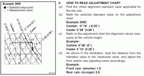
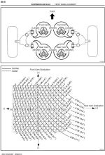
Caster is extremely hard to adjust without some sort of slip plate. Going to take a lot of trial and error to get it right. Will have to roll the truck back and forth after each adjustment to relax the suspension. Check the graph in the pdf which will show you how to set the gradients on the cams to get the appropriate angles. Just an FYI, on our trucks, caster and camber are set simultaneously.
 

Attachments

Caster can be measured indirectly by measuring camber change as the wheels are steered a known amount (usually 20 degrees) left and right. So, assuming you're measuring the driver's side wheel, here's the process.
- turn wheels 20 degrees right
- measure camber - call that angle A
- turn wheels 20 degrees left
- measure camber again - call that angle B.
- caster = (B-A)*1.5

So, for example, if angle A = -.5 degree and angle B = +1 degree, then
caster = (1 - (-.5))*1.5=(1+.5)*1.5 = 2.25 degrees.

Keep in mind that, if your back wheels are higher or lower than the fronts, that will affect the apparent caster measurement by the amount of front-back slope in degrees. You just need to add or subtract that value from the computed value above.

The previous poster is correct in that a slip plate (or a couple of pieces of cardboard) under the wheels is helpful to keep tension off the suspension and steering while you are turning the wheels back and forth. Given that, if you have a good angle gauge you can get surprisingly good results with the method above. I use a string and weight to measure the vertical camber angles. It's cheap, easy to make, and gravity always points straight down - no calibration required. Easy to read to .1 degree.
 
Caster is extremely hard to adjust without some sort of slip plate.
I saw on the net that some folks used cardboard, others linoleum tiles with baby powder in between and one used 6" by 6" 3/16th-inch aluminum plates with grease (they called it a grease sandwich).
8984663.jpg


I like the idea of four greased steel plates (or aluminum to prevent rust friction) of about 8 inches square each.
Would that grease sandwich work for the 4Runner?

Going to take a lot of trial and error to get it right. Will have to roll the truck back and forth after each adjustment to relax the suspension.
I watched an alignment and they never rolled it back and forth.
Does their machine bounce it?
Or are their slip plates fantastic?

Check the graph in the pdf which will show you how to set the gradients on the cams to get the appropriate angles. Just an FYI, on our trucks, caster and camber are set simultaneously.

Thanks for that information that caster/camber are set at the same time and for that graph where you put the desired point and what you currently have and then adjust in the direction the graph tells you.

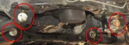
One question, born out of ignorance of the actual process, since there are four adjustment bolts, two for each side, is whether they're done simultaneously or one at a time? (The PDF says "adjust one and/or the other accordingly" so I'm just asking what that means, in practice.)
 

Attachments

  • chart.gif
    chart.gif
    59 KB · Views: 1,589
Last edited:
I use a string and weight to measure the vertical camber angles. It's cheap, easy to make, and gravity always points straight down - no calibration required. Easy to read to .1 degree.

When I searched for other people who did this, I found some used what seems to be a similar method but I don't know how you gauged the angle of the string (I guess by eye).
P1110544.jpg~original


- turn wheels 20 degrees right
- measure camber - call that angle A
- turn wheels 20 degrees left
- measure camber again - call that angle B.
- caster = (B-A)*1.5

Thanks for that hint because, as you said, camber will be relatively easy to measure with a level that is accurate to 1/10th of a degree (six minutes).

Then with that chart above, we know which way to turn the eccentric bolt.

I'm just curious since nobody mentioned the markings on the bolts which seem to be in degrees of some sort.

Why do these plates have those markings on them (are the markings useful to us)?
 

Attachments

  • 8975532.jpg
    8975532.jpg
    78.1 KB · Views: 2,810
Last edited:
The markings on the cam bolts refer to the divisions on the graphs in the FSM. Once you figure out how much you need to adjust camber and caster, then go to the graph and it will tell you (if you read it properly, not trivial), how many marks to rotate each cam bolt. For caster and camber, the wheels are independent, so adjust the two cam bolts on the driver's side, and then move to the passenger side.

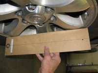
As far as the vertical angle scale, I made a board out of masonite with a straight edge that will fit against the rim (approx. 16" long). Then attach a string and weight to the top, and paste a carefully calculated angle scale on the bottom. Here's a picture. Just lay the long edge against the wheel and read the camber angle on the scale.

Here are some pics. Later when I have more time I can post the formula for making the angle scale. (Sorry about the rotated pictures. I don't know offhand how to fix that.)

As an FYI, the picture shows a camber angle of about -.1 degrees. (Leaning in at the top of the wheel). Each minor tick on the scale is .2 deg.
 

Attachments

  • IMG_6310.jpg
    IMG_6310.jpg
    131.6 KB · Views: 1,457
  • IMG_6312.jpg
    IMG_6312.jpg
    129 KB · Views: 1,300
Last edited:
Caster can be measured indirectly by measuring camber change as the wheels are steered a known amount (usually 20 degrees) left and right. So, assuming you're measuring the driver's side wheel, here's the process.
- turn wheels 20 degrees right
- measure camber - call that angle A
- turn wheels 20 degrees left
- measure camber again - call that angle B.
- caster = (B-A)*1.5

So, for example, if angle A = -.5 degree and angle B = +1 degree, then
caster = (1 - (-.5))*1.5=(1+.5)*1.5 = 2.25 degrees.

Keep in mind that, if your back wheels are higher or lower than the fronts, that will affect the apparent caster measurement by the amount of front-back slope in degrees. You just need to add or subtract that value from the computed value above.

The previous poster is correct in that a slip plate (or a couple of pieces of cardboard) under the wheels is helpful to keep tension off the suspension and steering while you are turning the wheels back and forth. Given that, if you have a good angle gauge you can get surprisingly good results with the method above. I use a string and weight to measure the vertical camber angles. It's cheap, easy to make, and gravity always points straight down - no calibration required. Easy to read to .1 degree.

Correction here, it's 20° total,(not counting VW and Tesla) so the turn in would be 10°, then 20° turn out. The specs are not written for a 40° swing. Which brings up the same problem for the OP, if you don't have graduated turntables, how is he going to know how to do his caster swing?

I'm not sure what the end game is here for the OP, is it learning alignment angles, saving money, just doing it yourself? I've aligned my own vehicles using 2x4's and strings, but that was just to get to the shop. I used to own my own caster/camber gauge, toe in bar and scribe too, but even that was just to get me in the game. A good 4 wheel alignment requires thrust angle measurement, and even a 2 wheel alignment benefits from knowing the thrust angle. At the track race car guys use toe plates to get them through the day, but in this situation it sure seems like a lot of expense and work to get it "close".
 
Jeez, I feel really stupid. How do you do a half-spin? You don't put the end on upside down, do you? It's conical, right? I guess this is why I went over on my toe-ins.

Be gentle. I said I was outside my comfort zone.


Well you just turn the INNER rod half a turn. Thanks for the cheat sheet!

:hail:Ω

See what I did there?
 
Correction here, it's 20° total,(not counting VW and Tesla) so the turn in would be 10°, then 20° turn out. The specs are not written for a 40° swing. Which brings up the same problem for the OP, if you don't have graduated turntables, how is he going to know how to do his caster swing?

I'm not sure what the end game is here for the OP, is it learning alignment angles, saving money, just doing it yourself? I've aligned my own vehicles using 2x4's and strings, but that was just to get to the shop. I used to own my own caster/camber gauge, toe in bar and scribe too, but even that was just to get me in the game. A good 4 wheel alignment requires thrust angle measurement, and even a 2 wheel alignment benefits from knowing the thrust angle. At the track race car guys use toe plates to get them through the day, but in this situation it sure seems like a lot of expense and work to get it "close".

The formula I posted is for a 20 degree swing each way. For a 10 degree swing each way it would be (B-A)*2.9. It doesn't matter what angle you run the steering through as long as you use the right factor in the multiplication. It's just trigonometry.

It's pretty easy to measure 20 degrees of steering deflection. I just cut a board with a 20 degree angle between sides and match the wheel to that. If you're off by a degree (which is pretty easy to see) it affects the caster measurement a little over .1 degree.

Not sure why you are so negative about DIY. I think it's very useful to understand how the alignment process works - it puts you less at the mercy of marginally trained techs who don't really understand the process either, but just follow a set of computer instructions.

You can easily and repeatably measure caster to .3 degrees in the way I've described, and that's plenty good for a road vehicle. The Toyota spec is +/- .75 degrees, and .75 deg match side to side.

On a 4th gen (not sure about a 3rd, but my guess is it's similar), caster changes .3 degrees for each inch of front end ride height change, and with stock springs the front height changes about .2 inches for each 100 lbs of loading. Rear end loading will increase this change. So, adding two 150 lb passengers to the front seat changes your caster by about .2 degrees. Unless you are going to have alignments done while your wife and kids and dog are in the car, you can't maintain better than a few tenths of a degree anyway. Measuring camber or caster to .01 degrees makes no more sense than measuring your battery voltage to 1 mV. Just because something can be done, doesn't mean it's particularly useful.

Toe needs to be done with more care because of its strong effect on tire wear, but also is easily done in your garage. It just depends on how much care you can and want to take. The string method works very well and is quite accurate. It's satisfying to understand what's going on and be able to set up your vehicle the way you want. And given the horror stories I hear about "professional" alignments on this forum, if nothing else it's worth knowing how to check for being in the ballpark after you've had it to the shop, especially when you're dealing with modified suspensions which don't fit the normal shop expectations.

There's really no such thing as a 4wheel alignment for a 4runner. The rear axle is fixed, so it is what it is. Front caster, camber, and toe are all you have to work with.
 
Jeez, I feel really stupid. How do you do a half-spin? You don't put the end on upside down, do you? It's conical, right? I guess this is why I went over on my toe-ins.

Be gentle. I said I was outside my comfort zone.


Well you just turn the INNER rod half a turn. Thanks for the cheat sheet!

:hail:Ω

See what I did there?

I knew you'd like the Ω.

Yeah, I thought that was the answer. I didn't know you could do that without messing up the boot so I left the inner alone. Live and learn. My first alignment...thanks.
 
Last edited:
The formula I posted is for a 20 degree swing each way. For a 10 degree swing each way it would be (B-A)*2.9. It doesn't matter what angle you run the steering through as long as you use the right factor in the multiplication. It's just trigonometry.

It's pretty easy to measure 20 degrees of steering deflection. I just cut a board with a 20 degree angle between sides and match the wheel to that. If you're off by a degree (which is pretty easy to see) it affects the caster measurement a little over .1 degree.

Not sure why you are so negative about DIY. I think it's very useful to understand how the alignment process works - it puts you less at the mercy of marginally trained techs who don't really understand the process either, but just follow a set of computer instructions.


There's really no such thing as a 4wheel alignment for a 4runner. The rear axle is fixed, so it is what it is. Front caster, camber, and toe are all you have to work with.

I hear you about marginally trained techs, but those are the ones that get talked about. There are plenty of competent people out there doing hundreds of thousands of alignments. When it takes 12 posts to explain how to measure toe in inches, I start to wonder about the viability, of a good DIY alignment. Baby powder and plywood doesn't get it with 2400# of truck. Believe me I know it can be done, my question is simply why, when the options are so simple.

Just because there is no adjustment for the live axle does not mean you shouldn't know where it is. IT DOES affect what the front wheels do, and thrust angle does matter.

I could grow chickens to get some eggs for breakfast, that doesn't mean I should.
 
I could grow chickens to get some eggs for breakfast, that doesn't mean I should.
But it doesn't mean someone shouldn't either. I have two neighbors who raise chickens for eggs, and those eggs are definitely as good as the "professionally raised" store-bought ones:-)

I hear you about marginally trained techs, but those are the ones that get talked about. There are plenty of competent people out there doing hundreds of thousands of alignments. When it takes 12 posts to explain how to measure toe in inches, I start to wonder about the viability, of a good DIY alignment. Baby powder and plywood doesn't get it with 2400# of truck. Believe me I know it can be done, my question is simply why, when the options are so simple.

And I don't disagree that, for most people, having a shop do their alignments is the way to go. But the OP was asking some good questions about whether it was possible, and how to do it, and I felt moved to supply some answers. Even if he doesn't do it, it can't hurt to have an understanding of what's going on.

I'm an engineer and an inveterate DIY'er. I enjoy understanding how things work and figuring out how to reduce these arcane processes to understandable fundamentals. And, I'm pretty good at precision measurements, attention to detail, and understanding sources of error - in the electronics world that's how I make my living. So DIY alignments are something I've studied and done with good success.
 
Last edited:
Even if he doesn't do it, it can't hurt to have an understanding of what's going on.

Thank you for understanding that the whole point is to understand what can be adjusted, and, if it's possible, at home, to take a stab at it.

What's the worst thing that can happen?

I learn something and I might also screw up the alignment
But so what.

If I screw up the alignment, the worst thing that happens is that it costs me a hundred bucks to have someone else set the front caster, camber, and toe.

There's only so much we learn by watching others do our work; but we learn a ton when we have to think all the steps involved, starting from new tires to alignment.

In fact, the tires are scheduled to arrive tomorrow so I'll soon be mounting the tires and balancing them in my driveway, so I will write up what I learn doing that, over here:
 
Last edited:
The markings on the cam bolts refer to the divisions on the graphs in the FSM. Once you figure out how much you need to adjust camber and caster, then go to the graph and it will tell you (if you read it properly, not trivial), how many marks to rotate each cam bolt.

Thanks for that clarification because I must admit I'm not clear on how the chart works yet with respect to the adjustment marks on the eccentric plates (if that's what they're called) but when I start doing the measurements and trying to adjust things, I think it will become more clear to me so I don't have questions yet (since I have to study the chart more first).

I found some more specs by googling, which have an expanded chart as can be seen below for 4Runner.
 

Attachments

Last edited:
Thanks for that clarification because I must admit I'm not clear on how the chart works yet with respect to the adjustment marks on the eccentric plates (if that's what they're called) but when I start doing the measurements and trying to adjust things, I think it will become more clear to me so I don't have questions yet (since I have to study the chart more first).

I found some more specs by googling, which have an expanded chart as can be seen below for 4Runner.

The cam marks are easy. But yes the chart can be challenging. The axis are obviously rear cam and front cam. The cams have 20 gradients. The center is 0. When you turn the cams outward toward the wheel, you are shortening the LCA which is making it negative, vice versa positive. So say you turn both all the way to -10, (both 90 degrees towards the wheels) you plot that point and by looking at the solid line (camber) and broken line (caster), you end up with a little more than a degree of positive camber and about 2.75 degrees of caster.
 
The cam marks are easy. But yes the chart can be challenging. The axis are obviously rear cam and front cam.
Heh heh ... that's not so "obvious" but now it is, now that you mentioned it, that is! :)

Thanks. I have been concentrating on the wheel mounting and balancing, so it will be a week or two before I get to the alignment part of the job.

I'm sure that's when this chart will begin to make sense to me.
Right now I'm just lining up the ducks.

The cams have 20 gradients. The center is 0. When you turn the cams outward toward the wheel, you are shortening the LCA which is making it negative, vice versa positive.
Thanks. I will keep that in mind when I need to "shorten" or "lengthen" the Lower Control Arm to change camber/caster.

Since measuring camber is easier than measuring caster, right now I'm looking up the formulas for calculating caster by measuring camber so that I get a "feel" for how that works (right now it's as clear as mud to me that you can calculate caster from a measured camber - but that's because I need to work on the basics).

So say you turn both all the way to -10, (both 90 degrees towards the wheels) you plot that point and by looking at the solid line (camber) and broken line (caster), you end up with a little more than a degree of positive camber and about 2.75 degrees of caster.

That doesn't make sense to me yet, but it's because I need to think slowly about it when I'm doing it, so I'll have questions later - but I need to work on some of the basics offline on my own first.
 
Here's the math behind calculating caster from measured camber.

The fundamental relationship is:

DeltaCamber=Caster*Sin(deltaSteeringAngle from straight ahead)

To put this into practice,
Assume a steering angle "A" (e.g., 20 degrees outboard). The associated measured camber angle is CamberA
Assume a 2nd steering angle "B" (e.g., -20 degrees inboard). The associated measured camber angle is CamberB.

Now, if we assume angle A = angle B, we can rearrange the fundamental equation above, combine both measurements, and get:

Caster = (CamberA - CamberB)/(2*sin(A))

Where (CamberA - CamberB) is the algebraic difference of the two measured camber angles. E.g., if CamberA=+1.5 and CamberB=-1, (CamberA-CamberB)=(1.5-(-1))=2.5

So, for 20 degrees outboard and inboard, sin(20)=.342

Therefore Caster=(CamberA-CamberB)/(2*.342)=(CamberA-CamberB)/(.684)~=(CamberA-CamberB)*1.5.

That's the quick formula I gave you a few posts ago.

For the example values of measured camber above, this would give a caster angle of about 2.5*1.5=3.75 deg.

The theory around this is that the steering axis runs through the ball joints. The fore/aft angle from the upper to the lower ball joint is the caster angle. As you steer the wheels around the steering axis, the wheels tilt (change camber) following the relationship I gave above. (It might help to visualize steering the wheels a full 90 degrees. At that point the "lean" (measured camber) of the wheels would be equal to the caster angle. That fits our formula, since sin(90)=1. We can't turn the wheels that far, so we have to use the trig formulas to make the calculation work for smaller angles).

So, by accurately measuring camber at known angles away from straight ahead, caster can be calculated. Camber is easy to measure with the plumb line gauge I showed earlier, or with a carefully calibrated and accurately scribed level.

There is a second order effect due to non vertical steering axis inclination (the side to side tilt of the steering axis). SIA is normally in the neighborhood of 10-12 degrees, and at that level causes this formula to be in error < 2%. The error is the same for both sides of the vehicle, so does not affect caster match side to side.
 
Last edited:
Here's the math behind calculating caster from measured camber.

The fundamental relationship is:

DeltaCamber=Caster*Sin(deltaSteeringAngle from straight ahead)

I am confused because I don't see that equation elsewhere so I am trying to understand how that equation comes about so this post will be confusing and incomplete but I'll be working on it so please do know that I much appreciate your advice and I am slowly internalizing each component of it (but I am slow and methodical so it may take me a while to understand how that black magic equation came about).

Googling for how to derive the equation above, I find this equation:
Caster in degrees = (180 / pi) * [(camber1 - camber2) / (turnangle1 - turnangle2)] for equal and opposite turn angles.

In practice, it seems that the theoretical equation (which requires SAI for example) is simplified, which will be the equation I will be using in the end.
For example, having the same inboard and outboard steering angles is one simplification, where one complete steering wheel revolution is a useful metric because it's reproducible once initially measured how many degrees result.

In looking things up, I found out why we can't measure caster directly, which is explained here, as "Caster cannot be measured directly, since one cannot mount a sensor on an imaginary steering axis."

That PDF (attached below) derives some of the equations, but I'm still working on understanding the derivation (and simplifications of SAI).

BTW, this method of measuring camber seems like the easiest and least expensive way to do it at home (you only need a caliper and a standard bubble level).
 

Attachments

Last edited:
Status
Not open for further replies.

Members online

No members online now.

Forum statistics

Threads
278,316
Messages
3,554,111
Members
248,016
Latest member
Advally Service

Trending content

Back
Top