Wire Switch to all Interior Lights for On/Off Ability?

derekl123

New member
Came across J.A's mods on the map light and footwell. In addition to doing these two mods, I'd like to add another switch that lets me turn off/on all of the interior lights (map light, door lights, dome light, cargo light) on demand. Based on the diagram below, would it just involve cutting the "Red with Green stripe" wire at Pin 9 of the 1K Connector and wiring it like so on a SPDT switch:

  • Prong 1: Chassis Ground
  • Prong 2: One side of Pin #9
  • Prong 3: Other side of Pin #9

This way, the up position (Prong 1/2) turns all of the lights on and the down positions (Prongs 2/3) keeps the ILE running as normal. Does this sound right? Would there be any danger to doing it this way (door open indicator while driving)? I'd like to have the ability to turn all the interior lights on while driving.

Td52j33.png
 
Last edited:
Register to hide this ad
I've thought about doing this too. Someone found out that Pin 16 on the same connector is part of the ILC which is an open pin. So an easier way would be to ground Pin 16 through a switch.

As far as errors - I don't know either. I'm not positive but I think the door open indicator while driving is through the door switches, not the light circuit.

Good luck.
 

From the other schematics on JA's site, it looks like the red wires are constant +12V coming from the dome relay (see here), which means that all other color wires are the various ground paths for the different lights. I think your suggestion of adding a switch to ground on R/G will only allow you to light up the ignition key cylinder light; from what I can tell, none of the other lights will have a new path to ground beyond the factory grounding through the ECU.
 
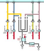
I drew this up for another guy a while back. This should help you accomplish what you are trying to do.

door lights3.jpg

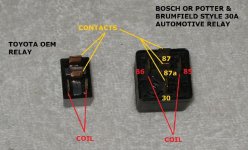
I've also included this info about relays if you haven't messed around with them much. You can use an OEM Toyota relay, or an aftermarket Bosch style 30A relay. I labeled the contacts to use so, but if you have any questions, ask.

P8046792.jpg
 

Attachments

  • door lights3.jpg
    door lights3.jpg
    66.8 KB · Views: 5,797
  • P8046792.jpg
    P8046792.jpg
    77 KB · Views: 3,866
Last edited:
I drew this up for another guy a while back. This should help you accomplish what you are trying to do.

View attachment 167861

I've also included this info about relays if you haven't messed around with them much. You can use an OEM Toyota relay, or an aftermarket Bosch style 30A relay. I labeled the contacts to use so, but if you have any questions, ask.

View attachment 167862

Makes a lot more sense now. I was reading the schematic wrong.
 
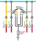
One other possibility for wiring this up would be without the relay, but only if you are using a good quality switch, which is rated for at least the amperage rating that would be running through it. Frankly, it won't be that much considering it'll just be the interior lights, and maybe running board lights, footwell lights, and whatever else you may have added.

I would still suggest connecting a multimeter up to verify before foregoing using the relay. Anyway, here's the diagram for that:

door lights4.jpg
 

Attachments

  • door lights4.jpg
    door lights4.jpg
    67.6 KB · Views: 4,363
One other possibility for wiring this up would be without the relay, but only if you are using a good quality switch, which is rated for at least the amperage rating that would be running through it. Frankly, it won't be that much considering it'll just be the interior lights, and maybe running board lights, footwell lights, and whatever else you may have added.

I would still suggest connecting a multimeter up to verify before foregoing using the relay. Anyway, here's the diagram for that:

View attachment 167863

So after I do this wiring, if I were to open one door instead of just that open door's courtesy light turning on, it would cause all of the door courtesy lights to turn on (Since they'll be wired so that the ground signal of the open door could go to all 4 door lights)?
 
No. The diodes will prevent that.

One more question. In your diagram, this would only allow me to either turn on the door lights or keep them automatic. If I wanted to turn them all off, would I have to keep each door ground signal separate and use something like a 4 individual SPDT switches (or 2 DPDT) so I can have off, on and normal capability?
 
Last edited:
What do you mean by automatic?

If you mean have them shut off if you forget to shut them off manually (as the body control unit does), then you would have to wire it up with the relay, and wire the 12v input with only having power when the ignition is in acc, or on.

If that's not what you mean, please explain.
 
What do you mean by automatic?

If you mean have them shut off if you forget to shut them off manually (as the body control unit does), then you would have to wire it up with the relay, and wire the 12v input with only having power when the ignition is in acc, or on.

If that's not what you mean, please explain.

By automatic I mean they operate as normal. Whatever door opens, only that door's light turns on.
 
I think "automatic" means "OEM functionality" in this case.

Derekl123, if you also want to have the ability to turn off all the lights you don't necessarily need to wire up individual switches for each lamp. You could instead use a single switch on the incoming +12V from the dome relay to cut power to all lights. Even better: you could purchase a DPDT switch in on-off-on (3 position, center off). Use 1 pole for factory grounding or A/V1's grounding circuit to switch from "auto" to "on", and the other pole to interrupt the +12V supply to the lights. This would make your switch functionality down=auto, center=off, and up=on (or the reverse of that), similar to how the overhead dome light switches are arranged.
 
I think "automatic" means "OEM functionality" in this case.

Derekl123, if you also want to have the ability to turn off all the lights you don't necessarily need to wire up individual switches for each lamp. You could instead use a single switch on the incoming +12V from the dome relay to cut power to all lights. Even better: you could purchase a DPDT switch in on-off-on (3 position, center off). Use 1 pole for factory grounding or A/V1's grounding circuit to switch from "auto" to "on", and the other pole to interrupt the +12V supply to the lights. This would make your switch functionality down=auto, center=off, and up=on (or the reverse of that), similar to how the overhead dome light switches are arranged.

This is a much simpler option than what I was thinking. Thanks.
 
By automatic I mean they operate as normal. Whatever door opens, only that door's light turns on.

Ok, the way my mod is drawn up, when the switch is off, your interior lights will operate as the Toyota engineers designed them to. Including only the particular door lamp which is opened to illuminate.

With the switch on, then a ground would be provided, all interior lights would then turn on (provided the roof lamp switch positions are set to the proper position), ALL door lamps will turn on, whatever added footwell lighting you may have added to the circuit should turn on as well.

The only difference between opening a door, and flipping your switch is that basically, the door circuit goes through the body ECU and will automatically shut off the interior lamps after I believe it's 30 minutes.

Of course, with your switch, you aren't using the body ECU, so it WILL NOT shut off the lights automatically. They will stay on as long as that switch stays on. That is, unless you use the relay method, and power the relay with a source that only has power when the ignition is in ACC or ON. Then you are essentially making your own auto off.

If you want to make it so NONE of your interior lights come on, then that's a different story. But again, pretty easy to do.

Clear as mud?:confused:
 
I think "automatic" means "OEM functionality" in this case.

Derekl123, if you also want to have the ability to turn off all the lights you don't necessarily need to wire up individual switches for each lamp. You could instead use a single switch on the incoming +12V from the dome relay to cut power to all lights. Even better: you could purchase a DPDT switch in on-off-on (3 position, center off). Use 1 pole for factory grounding or A/V1's grounding circuit to switch from "auto" to "on", and the other pole to interrupt the +12V supply to the lights. This would make your switch functionality down=auto, center=off, and up=on (or the reverse of that), similar to how the overhead dome light switches are arranged.

Exactly!
 

I think "automatic" means "OEM functionality" in this case.

Derekl123, if you also want to have the ability to turn off all the lights you don't necessarily need to wire up individual switches for each lamp. You could instead use a single switch on the incoming +12V from the dome relay to cut power to all lights. Even better: you could purchase a DPDT switch in on-off-on (3 position, center off). Use 1 pole for factory grounding or A/V1's grounding circuit to switch from "auto" to "on", and the other pole to interrupt the +12V supply to the lights. This would make your switch functionality down=auto, center=off, and up=on (or the reverse of that), similar to how the overhead dome light switches are arranged.

Perfect! This was just my thinking! I love these threads! The initial idea was wanting the ability to open the door without having the lights come on. I know there is a momentary switch on the doors that control this.

But the ability to turn ON, OFF and AUTO (OEM functionality), would be much more desirable.

I do know the basics of DC circuity - but not enough to start introducing and splicing extra wires. I'm a bit lost how when you mention implementing a DPDT (6 total contacts) to achieve this. Would you mind drawing a quick sketch?

Thanks again
 
I've also included this info about relays if you haven't messed around with them much. You can use an OEM Toyota relay, or an aftermarket Bosch style 30A relay. I labeled the contacts to use so, but if you have any questions, ask.

View attachment 167862

Does it matter which way I wire into the OEM Toyota Relay since they aren't labelled 86, 85, 87, 30? I am trying to wire in some rock lights to work with my ILE circuit. Thank you!

Here's the wiring diagram I am using.

domerockv4_wiringdiagram_switch-jpg.3483898
 
Last edited:
Yes, all relays work the same. There are 2 wires for the coil that need power and ground. You control one side of that to turn the relay on and off. You can tell which pair it is with an Ohm meter, it will show a few ohms resistance. If you have 5 legs total on the relay then there will be a common leg on the 3 left (minus the coil), it would show 0 ohms to one other leg and open to the last leg. Power the coil and this should reverse. If only 4 legs total then just 2 legs that turn on/off with the coil powered. If you don't have an ohm meter you can put a 9v battery across a pair of terminals at a time to see which one makes it click, those will be the control leads. What is left will be the switched part. Do not use a car battery to find the correct leads because you could fry the relay.

Here's one type of Toyota relay.

Denso Relay 4 Pin Wiring Diagram - Benign Blog
 
I think "automatic" means "OEM functionality" in this case.

Derekl123, if you also want to have the ability to turn off all the lights you don't necessarily need to wire up individual switches for each lamp. You could instead use a single switch on the incoming +12V from the dome relay to cut power to all lights. Even better: you could purchase a DPDT switch in on-off-on (3 position, center off). Use 1 pole for factory grounding or A/V1's grounding circuit to switch from "auto" to "on", and the other pole to interrupt the +12V supply to the lights. This would make your switch functionality down=auto, center=off, and up=on (or the reverse of that), similar to how the overhead dome light switches are arranged.

I'm looking to do exactly this (kill switch for all interior lights) and thought the 12V+ from the dome relay was the red wire here: http://www.top4runners.com/cgi-bin/image.pl?/ja/2007/footwells/footwellsa.jpg - but when I cut that wire, the dome lights still stay on. Does anyone know which wire I need to wire a switch inline in order to accomplish this? I'll be doing a lot of dispersed camping this summer and want to have a single switch to kill all the interior lighting so it doesn't affect my night vision when I open a door.
 

Members online

Forum statistics

Threads
278,310
Messages
3,554,080
Members
248,016
Latest member
Advally Service

Trending content

Back
Top