Wiring help

T101

New member
How would I do this?....

I'd like to hook up LED cube amber lights using ditch light mounts, with a manual switch in cab to make the lights stay on.

I'd like that when I have the switch 'off' that the lights would act as turn signals.

This much so far I can handle no problem, I know how to use relays, I'm good with pretty basic automotive wiring. But...

How would I wire everything so that when I have the switch 'on' and the LED/ditch lights are steady illuminated, that the turning signal will still work in the new LED/ditch light?? I think there would have to be either resistors, or some reverse polarity, but it's a bit past my knowledge level. Please help me. And yes, I tried searching, nothing came up.

Thank you
 
Register to hide this ad
How would I do this?....

I'd like to hook up LED cube amber lights using ditch light mounts, with a manual switch in cab to make the lights stay on.

I'd like that when I have the switch 'off' that the lights would act as turn signals.

This much so far I can handle no problem, I know how to use relays, I'm good with pretty basic automotive wiring. But...

How would I wire everything so that when I have the switch 'on' and the LED/ditch lights are steady illuminated, that the turning signal will still work in the new LED/ditch light?? I think there would have to be either resistors, or some reverse polarity, but it's a bit past my knowledge level. Please help me. And yes, I tried searching, nothing came up.

Thank you
I don't see how "resistors" or "reverse polarity" would help you here? just use a double throw relay with inputs from the turn signals and the + from the switch or could probably get away using a diode? [MENTION=93434]gshadow325[/MENTION] can draw a champ diagram
 
Last edited:
Simple question that requires lots of knowledge.

Tell me how you are to wire your lights right now.

Then I can insert my solution.
So far it involves two diodes and two relays
 
[MENTION=55855]zopperman[/MENTION] i figured it out. curious if this is a one hit wonder question that will never get a reply. LOL

i need to know, your switch. will it over ride turn signals or is turn signal the priority.

you will need to build two sets of these one for each side.

i have my plans drawn out.
 
This is what I started with until I realized my dummy mistake that the front blinkers bulbs are actually always on, and that this diagram would essentially keep the ditch lights always on as well, and wouldn't have the ability to turn them on/off by the switch.

I suppose if i tapped into the + lead from the rear blinkers, that this diagram would essentially accomplish the first 2 parts of my original post, but that would require 2 more diodes, and it wouldn't accomplish the 3rd function I was looking for.

I'm assuming there's a much easier way?

ditch wiring 1.jpg
 

Attachments

  • ditch wiring 1.jpg
    ditch wiring 1.jpg
    51.7 KB · Views: 1,210
close.

there would need to be two mote diodes doide what you are doing. you will be turning on the blinkers each time you turn on the switch.

so you didnt answer my question.

what will have priority?

turn signals or dirch lights. if switch is on, do the turns signals still blink the lights?

or switch turns the lights on regardless.
 
99 problems and a switch is one

close.

there would need to be two mote diodes doide what you are doing. you will be turning on the blinkers each time you turn on the switch.

so you didnt answer my question.

what will have priority?

turn signals or dirch lights. if switch is on, do the turns signals still blink the lights?

or switch turns the lights on regardless.

I guess the switch would have priority.

Would like ditch's to always act as turn signals along with factory signals still functioning, regardless if switch is flipped 'on' or 'off.

Beyond confused about if I have switch flipped 'on', and ditch's are getting constant power from the relay (via the switch +), how to get the blinker to override the constant power from the switch.

like this.... right blinker on, switch 'off, left ditch unlit, right ditch blinking.

Right blinker on, switch 'on', left ditch solid lit, right ditch blinking, and vice versa, if that makes sense.
 
Stop thinking cause what I'm going to tell you will blow your mind after I finish this remote starter in this 2014 Nissan maxima. Give me a few minutes to draw it to for you.
 
to accomplish #3, i had to reread what you wanted to do.

take off your 12v triggers from the turn signal.

get another 2 relays

30 to ground
87 to 85 on your first two relay
86 to 12v switched 12volt
85 12v from your parking light

"Why would that work steve? You are supplying 12v to bolt sides of the relay!!"

Correct, i am supplying 12volt but when the light bulb is off, its giving you a ground. so each time the turn signal gives 12 volts the relay clicks OFF, thus taking the ground from the first relay and making it turn off. then when power goes to the bulb goes off the realy clicks on and feeds ground to the first relay thus turning it on.

flow chart:

30 in is ground
86 switch 12volt. 1/2 the relay is energized
85 in from positive of turn signal. when bulb is off, ground flows back thru bulb to positive side, relay is on and completed
87 output from what is coming in from 30, ground goes to first relay #85.

FYI this will not work if you have LED bulbs in your turn signals. LEDS are polarity based and will not back flow a ground thru it. halogen bulbs do.
 
Last edited:
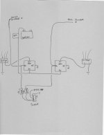
fd3648299b660c05b2a092ab600b0bd8.jpg


Picture :)
 
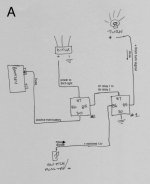
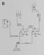
[MENTION=93434]gshadow325[/MENTION] thank you in advance. how does this look? Does the switched 12v+ go to just the first relay (pic "A") or both relays (pic "B")

See below pictures, relay marked #1 is how you explained, then #2 is left how I would wire just a simple switched aux light. Am I missing anything? Too many/ not enough /misplaced diodes?

ditch wiring.jpeg

ditch wiring copy.jpg
 

Attachments

  • ditch wiring.jpeg
    ditch wiring.jpeg
    74.9 KB · Views: 1,704
  • ditch wiring copy.jpg
    ditch wiring copy.jpg
    75 KB · Views: 1,585
Neither, sorry I wasn't clear.

When I mean switched 12 volt. I mean a 12 bolt source that will come on when the truck is started.

Your original schematic is fine just remove the input from the turn signals to where I said to put it in the second relay. Two relay for each side. No diodes needed.

Basically my additional delay will be powered up when the truck turns on. Then it will turn off when the turn signal goes to positive since the negative is dropping off.

Told you it was a trick move to get this to work.
 
Figure a will bit work because there is nothing connected to relay1 #86

Figure b will work if you want total control of the light with the switch.

The way I describe to do it. Switch can be on and it still Erik blink
 
Just looking it over and we can tweak it.

30 ground
87a to 85 on first relay
86 to positive of turn signal
85 ground
87 nothing.

This way relay is always at rested state in latched position. Then when the turn signal positive comes on it will open the relay this having the light turn off since it will take away the ground from first relay.
 
Neither, sorry I wasn't clear.

When I mean switched 12 volt. I mean a 12 bolt source that will come on when the truck is started.

Your original schematic is fine just remove the input from the turn signals to where I said to put it in the second relay. Two relay for each side. No diodes needed.

Yes, for my other auxiliary lights I used a fuse-tap on an unused slot in the in-cab fuse panel that's only powered with key turned on, would do the same for this.

Just looking it over and we can tweak it.

30 ground
87a to 85 on first relay
86 to positive of turn signal
85 ground
87 nothing.

This way relay is always at rested state in latched position. Then when the turn signal positive comes on it will open the relay this having the light turn off since it will take away the ground from first relay.

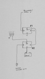
I tried making a diagram again using this ^^^... Is this what you meant?
And I'm supposed to tap the turn signal positive of the front or rear? Since the front signal bulb is always on (as a DRL) except for when flashing?

ditch wiring 1.jpg
 

Attachments

  • ditch wiring 1.jpg
    ditch wiring 1.jpg
    52.4 KB · Views: 1,066
DISCLAIMER:
You are giving this info free. YOu mess something up when you do this wrong dont blame me. I dont want to hear it nor am i accepting any responsibility for your lack of skills or knowledge using this info. Basically, you mess something up...oh well sucks for you!

WOW. cant believe i am spending so much time on this. freaking hungry now using so much brain power!!

This is real slick.

Relay #1 we will be using in reverse! this is to turn on ditch lights
Input will be 87
Output will be 30
At rest it will connect 30 and 87a input from relay #3 pole 87
12volt trigger will come from switch 86
ground will come from relay #2 pole 87a that passes thru 30 to ground

relay #2 we will be using to take away ground from relay #1. so at rest relay #2 is giving relay #1 ground. so relay #1 is waiting for a positive to turn on.

Separate switch ignition 12volt input will go to 86
as discussed above 30 will go to ground
87a will go to 85 on relay #1
input from the positve on the DRL bulb will go to 85. this wire will go to ground when the bulb turns off. thus opening relay #2 and taking away the ground from relay #1. if the switch is turned on 86 on relay #1 will have power and light will be on, taking the ground away will make the light turn off.

relay #3 will be giving power to the ditch light when relay #1 is at the rested position since 87a and 30 is connected at rest.
30 will be your fused 12v constant input
86 will be the same switched ignition input that you used for relay #2
85 will be the parking/drl positive line that goes to ground when the bulb is off. thus turning relay #3 on
87 will be the output going to 30 on relay #4 that passes thru to 87a when its not energize. this will go to 87a on relay #1. since 87a and 30 is connected at rest, this will turn on the ditch lights. at the same time ground is removed from relay #1 since relay #2 is opened with nothing outputting from 87. relay #3 also gets the same ground input. now it outputs what is coming in from 30 thru to pole 87 that goes to relay #1 pole 87a.

if relay #3 is turned on. power flows from 87 to 30.
when the turn signals get turned on the drl will give a ground to relay #2 that takes away ground signal from #1

all this is if the switch to turn on these lights are OFF.

Relay #4 will solve the problem when the switch is turned on. all of the above is when its in the off position

relay #4 is basically to over ride the ditch lights so they will actually turn off

30 is input from relay 3#
87a is output to 87a on relay #1
86 is input coming from your turn on switch
85 just goes to your normal ground

this bank of relays satisfies all 3 requirements
1: manual switch to have lights stay on
2: switch in off position, lights would act as turn signals
3: if lights are on steady, lights will still blink when turn signals are applied

searching will never yeild you any results since this is a real custom diagram/situation
[MENTION=55855]zopperman[/MENTION] you think this one thru yet? LOL
 
thank you [MENTION=93434]gshadow325[/MENTION]
gimme a few weeks to get the parts and be wired up. I'll take pictures and post a write-up when completed.
 
DISCLAIMER:
You are giving this info free. YOu mess something up when you do this wrong dont blame me. I dont want to hear it nor am i accepting any responsibility for your lack of skills or knowledge using this info. Basically, you mess something up...oh well sucks for you!

WOW. cant believe i am spending so much time on this. freaking hungry now using so much brain power!!

This is real slick.

Relay #1 we will be using in reverse! this is to turn on ditch lights
Input will be 87
Output will be 30
At rest it will connect 30 and 87a input from relay #3 pole 87
12volt trigger will come from switch 86
ground will come from relay #2 pole 87a that passes thru 30 to ground

relay #2 we will be using to take away ground from relay #1. so at rest relay #2 is giving relay #1 ground. so relay #1 is waiting for a positive to turn on.

Separate switch ignition 12volt input will go to 86
as discussed above 30 will go to ground
87a will go to 85 on relay #1
input from the positve on the DRL bulb will go to 85. this wire will go to ground when the bulb turns off. thus opening relay #2 and taking away the ground from relay #1. if the switch is turned on 86 on relay #1 will have power and light will be on, taking the ground away will make the light turn off.

relay #3 will be giving power to the ditch light when relay #1 is at the rested position since 87a and 30 is connected at rest.
30 will be your fused 12v constant input
86 will be the same switched ignition input that you used for relay #2
85 will be the parking/drl positive line that goes to ground when the bulb is off. thus turning relay #3 on
87 will be the output going to 30 on relay #4 that passes thru to 87a when its not energize. this will go to 87a on relay #1. since 87a and 30 is connected at rest, this will turn on the ditch lights. at the same time ground is removed from relay #1 since relay #2 is opened with nothing outputting from 87. relay #3 also gets the same ground input. now it outputs what is coming in from 30 thru to pole 87 that goes to relay #1 pole 87a.

if relay #3 is turned on. power flows from 87 to 30.
when the turn signals get turned on the drl will give a ground to relay #2 that takes away ground signal from #1

all this is if the switch to turn on these lights are OFF.

Relay #4 will solve the problem when the switch is turned on. all of the above is when its in the off position

relay #4 is basically to over ride the ditch lights so they will actually turn off

30 is input from relay 3#
87a is output to 87a on relay #1
86 is input coming from your turn on switch
85 just goes to your normal ground

this bank of relays satisfies all 3 requirements
1: manual switch to have lights stay on
2: switch in off position, lights would act as turn signals
3: if lights are on steady, lights will still blink when turn signals are applied

searching will never yeild you any results since this is a real custom diagram/situation
[MENTION=55855]zopperman[/MENTION] you think this one thru yet? LOL

I know this is only 9 years old but fantastic write up and solution [MENTION=93434]gshadow325[/MENTION]. Was trying to figure this out and the hamsters on my brain wheel exploded. Awesome!
 
DISCLAIMER:
You are giving this info free. YOu mess something up when you do this wrong dont blame me. I dont want to hear it nor am i accepting any responsibility for your lack of skills or knowledge using this info. Basically, you mess something up...oh well sucks for you!

WOW. cant believe i am spending so much time on this. freaking hungry now using so much brain power!!

This is real slick.

Relay #1 we will be using in reverse! this is to turn on ditch lights
Input will be 87
Output will be 30
At rest it will connect 30 and 87a input from relay #3 pole 87
12volt trigger will come from switch 86
ground will come from relay #2 pole 87a that passes thru 30 to ground

relay #2 we will be using to take away ground from relay #1. so at rest relay #2 is giving relay #1 ground. so relay #1 is waiting for a positive to turn on.

Separate switch ignition 12volt input will go to 86
as discussed above 30 will go to ground
87a will go to 85 on relay #1
input from the positve on the DRL bulb will go to 85. this wire will go to ground when the bulb turns off. thus opening relay #2 and taking away the ground from relay #1. if the switch is turned on 86 on relay #1 will have power and light will be on, taking the ground away will make the light turn off.

relay #3 will be giving power to the ditch light when relay #1 is at the rested position since 87a and 30 is connected at rest.
30 will be your fused 12v constant input
86 will be the same switched ignition input that you used for relay #2
85 will be the parking/drl positive line that goes to ground when the bulb is off. thus turning relay #3 on
87 will be the output going to 30 on relay #4 that passes thru to 87a when its not energize. this will go to 87a on relay #1. since 87a and 30 is connected at rest, this will turn on the ditch lights. at the same time ground is removed from relay #1 since relay #2 is opened with nothing outputting from 87. relay #3 also gets the same ground input. now it outputs what is coming in from 30 thru to pole 87 that goes to relay #1 pole 87a.

if relay #3 is turned on. power flows from 87 to 30.
when the turn signals get turned on the drl will give a ground to relay #2 that takes away ground signal from #1

all this is if the switch to turn on these lights are OFF.

Relay #4 will solve the problem when the switch is turned on. all of the above is when its in the off position

relay #4 is basically to over ride the ditch lights so they will actually turn off

30 is input from relay 3#
87a is output to 87a on relay #1
86 is input coming from your turn on switch
85 just goes to your normal ground

this bank of relays satisfies all 3 requirements
1: manual switch to have lights stay on
2: switch in off position, lights would act as turn signals
3: if lights are on steady, lights will still blink when turn signals are applied

searching will never yeild you any results since this is a real custom diagram/situation
[MENTION=55855]zopperman[/MENTION] you think this one thru yet? LOL

I know this is only 9 years old but fantastic write up and solution [MENTION=93434]gshadow325[/MENTION]. Was trying to figure this out and the hamsters on my brain wheel exploded. Awesome!
 

Members online

Forum statistics

Threads
278,304
Messages
3,554,041
Members
248,016
Latest member
Advally Service

Trending content

Back
Top