Performing the "Big 3" Wiring Ugrade on a 3rd Gen T4R - A How To

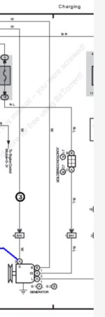
I realize this is an old thread (but still alive) and I appreciate the information, and plan to run some of this wiring. However, there is a problem, and a SERIOUS SAFETY ISSUE with this upgrade, specifically wire #8. The factory fuse link and 120 amp fuse are designed to protect the alternator, and the fuse link the rest of the vehicle wiring and components. By adding a second circuit with another 120 amp fuse, you are providing a 240 amp circuit when the engineers design it for 120 amp as a safety feature.

For example, if the fuse link blew (to protect the wiring and components in the vehicle), there would still be the second 120 amp path back through the fuse box via the alternator wire (#3 in your diagram). In reality, the fuse link would probably not blow at all until the total load reached 240 amps, when both fuses blow together (and maybe the fuse link). To make it simpler to understand, if the load reached 120 amps (the point the fuse should blow, by design) with this scenario, each circuit path would only have 60 amps flowing (since the current would be flowing equally in both paths), so neither fuse would blow (and your 4Runner might burn to the ground). In order to blow either 120 amp fuse, the load would have to reach 240 amps.

If you are going to use wire #8, you should pull off the fuse link (wire #1) and jumper the 120 amp alt fuse in the fuse box (or leave it be - a 120 amp fuse is essentially a jumper as far as the 30 amp fuse before it is concerned). That way the current from the battery will have 1 path, with a 120 amp fuse, to feed the fuse box and vehicle circuitry. The other option is to put a 60 amp fuse in each path (replace the 120 amp alternator fuse with a 60 amp, and use a 60 amp fuse on wire #8), for a total fuse capability if 120 amps.

I accidentally reversed the jumper cables while jump starting my wife's car recently and it blew the 120 amp alternator fuse, and 7 or 8 smaller ones. The 120 amp alternator fuse saved the alternator, ECM, and who knows what else. If it hadn't blow, I'd have been replacing lots of components and wiring harnesses (and maybe a car!) instead of 8 or 9 fuses.

Also, in your diagram, wire #8 connects to the 'B' terminal on the alternator, and the wire labeled as #3 is also the wire running from the 120 amp fuse to terminal 'B' on the alternator.
 
Last edited:
So what you are saying is that looking at the diagram, the components to the right of the alternator are now exposed to a 240A short whereas before they were only exposed to 120A .... ?

Because the components to the left should be fine. Each path will blow if 120A is exceeded, same as factory.
 

Attachments

  • tem999.JPG
    tem999.JPG
    31.2 KB · Views: 5,144
Last edited:
So what you are saying is that looking at the diagram, the components to the right of the alternator are now exposed to a 240A short whereas before they were only exposed to 120A .... ?

Because the components to the left should be fine. Each path will blow if 120A is exceeded, same as factory.

No. Two circuits (with the same resistance) in parallel, which is what this is, divide the total current flow equally between them. Since each path will flow equally, it will take 240 amps of current to blow EITHER of the fuses, which is twice the factory rating. As I said, if the total flow is 120 amps (which is where the factory fuse should blow) each fuse will only have 60 amps flowing through it (half the total current flow), so neither fuse will blow.

The safe way to do this is to remove (or disconnect) the wire from the fuse box to the alternator (wire #3 in the diagram) so there is only one fused path between the battery and the alternator (leave the fused link connected to the battery).
 
Last edited:
No. Two circuits (with the same resistance) in parallel, which is what this is, divide the total current flow equally between them. Since each path will flow equally, it will take 240 amps of current to blow EITHER of the fuses, which is twice the factory rating. As I said, if the total flow is 120 amps (which is where the factory fuse should blow) each fuse will only have 60 amps flowing through it (half the total current flow), so neither fuse will blow.

The safe way to do this is to remove (or disconnect) the wire from the fuse box to the alternator (wire #3 in the diagram) so there is only one fused path between the battery and the alternator (leave the fused link connected to the battery).

Let me start by saying I think the big 3 is big to do about almost nothing. I haven't done it to mine, nor do I intend to. 175K and no indication I will need it. Still I see the benefits IF, there is an alternator upgrade, or additional batteries, or you have not maintained the terminals/wires. So now to the problem.

Too many assumptions here. First the resistance in the two branches is NOT the same, that's the whole purpose of the upgrade. 2nd, if there would be a short to ground drawing big amperage, it would happen in an individual branch of the circuit. Since the current would take the path of least resistance, one branch fuse WOULD blow, most likely the added circuit breaker because that would be the path of least resistance. Of course you'd still have voltage, and therefore current flow because the 2nd branch would still be live. I haven't tested this, but I do think the 2nd fuse would then blow.

Now, if the alternator itself caused the short it would most likely draw all the battery could give, in which case 240A is nothing. Hell the starter could draw that much. Of course by design a short circuit anywhere in either branch would be just as catastrophic in terms of amperage draw.

And THAT is why this is really NOT a safety issue at all. Unless someone tells me that people doing the big 3 are burning their rigs to the ground.

That being said I agree with Ozark dude in that bypassing the original alternator circuit would be prudent. The redundancy is unnecessary anyway, and who wants to have to deal with a blown factory 120a fuse. Let the breaker do it's job and move on.

:snacker:
 
I'm about to do my big 3 and need to know what size lugs to buy. Are most of the bolts 5/16", 3/8" or a mix? If they are a mix then I'll just drill the 5/16" lugs to make them fit.
 
Anybody know how to get access to the fusible link inside the fuse box? I'm trying to replace the stock wire with a larger/longer one and I can't figure out how to get to it.
 
Just did this one tonight. Should help out my idle and starts since my ground wire was a joke. Someone ripped it off and replaced it with some measly thin little wire. Now it's a beefy 4 gauge wire and sets the stage for the other lighting and audio projects to come and not have to worry about frying that tiny wire to oblivion.
 
Wanted to share an update.

Driving the truck to work this morning and it idles MUCH better now. I think that's the gains to be had here, at idle it is smoother and has higher voltage. My wiring was damaged so I knew there was issues (had a few mechanics tell me the same thing) and when starting in extreme hot/cold conditions it was having trouble. Now runs like a top and it idle very smooth and about 200 RPM lower when cold and about ~50 RPM when hot. Very happy with how it turned out.

Other than my positive post being rusted together and my new terminal post being too big, this wasn't too bad. If if weren't for those hiccups I could have had it done in 2 hours or less.
 
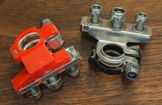
Here are the battery posts that I bought from Napa they are military grade. Negative post us on the battery and the positive is not yet, due to me not finishing the POSITIVE wires upgrade with 120amp.
NOTE: Stud for wires are facing sideways, compared to facing upwards.
]

Just got these off eBay for $12 shipped and wanted to show them to the members looking for multiple post connection points.

Will be ordering ready made 4AWG cables after I take some dimensions. Great thread...
 

Attachments

  • Battery Posts.jpg
    Battery Posts.jpg
    32.3 KB · Views: 2,551
I happened to be in West Marine (which is a boaters supply store) yesterday doing some Christmas shopping, and noticed they have a TON of large gauge wire and crimp connectors in there. You can buy the wire by the foot, and they had a crimping station set up where you could crimp the ends on right there in the store. That's a big deal, because a set of crimpers to do big cables like this the right way isn't cheap.

So, for anyone looking for parts to make this happen, check your local marine supplier. Most of the auto parts stores I've been in have a pretty limited selection of crimp connectors when you get up to these large sizes, and the don't sell the wire by the foot. :usa2:
 
Just got these off eBay for $12 shipped and wanted to show them to the members looking for multiple post connection points.

Will be ordering ready made 4AWG cables after I take some dimensions. Great thread...
These are nice. Are they military grade?
 
These are nice. Are they military grade?

I don't know what military grade actually means - care to offer a definition? They are eBay grade! You know what that means...

They are well made and plenty stout, and I hope the 'gauge' of steel used is equivalent to the electrical need. The nuts are Nylocks and the plastic pads are nice and heavy so I'm expecting them to be an improvement over other post designs.
 
Just got these off eBay for $12 shipped and wanted to show them to the members looking for multiple post connection points.

Will be ordering ready made 4AWG cables after I take some dimensions. Great thread...


These are just what I've been looking for!!
What was your search term or the seller's ID??

Thanks!!!
 
That being said I agree with Ozark dude in that bypassing the original alternator circuit would be prudent. The redundancy is unnecessary anyway, and who wants to have to deal with a blown factory 120a fuse. Let the breaker do it's job and move on.

:snacker:[/QUOTE]

Ok, so in regards to the numbered wires in the original post, you are saying to remove #3 and just run #8?
 
Alternator upgrade options: Need Advice

Hello all...
I am new to this site and very excited to be part of the community of 3rd Gen 4Runner owners.

I have a 98 4Runner (3rd gen) that i want to start upgrading. One of the first things I need to do is the "Big 3" and also replace my stock alternator which went bad last week. I am looking for a solid, reliable alternator that I can grow into as I begin my upgrades.

There are very few options that I can find for an alternator that fits a '98 4Runner. Unfortunately they tend to be pretty pricey. Here is what I have found:

(It would be nice if the alternator was plug-in-play.)

QUALITY POWER
160 amps $305
Toyota 4Runner High Output Alternators

MEAN GREEN
200 amps $400
2003-96 4-RUNNER 3.4L - MG Industries Inc.

DC POWER
180 amps $470
https://www.dcpowerinc.com/fit/Toyota~4Runner~1998~3.4L-V6-5VZ-FE/13671-180-hp.html

POWER BASTARDS
220 amps $350
220AMP Alternator for Imports and Domestics - Fitzall-220 | PowerBastards.com

based on a calculator I found on the web, I would need at least 200A to fun the base truck electrical, AC, Fog lights, off road LEDs, air compressor, winch, power inverter --- which not all of these would be run at the same time. Based on just running basic electrical, AC and lights - I need at least 150A. Then add in one of (inverter, winch, compressor) I need upwards of 180A.

I would love to get some opinions from everyone.

Is there another alternator out there I am not aware of?
What have you installed?
What has worked reliably?

THANK YOU!
 
Hello all...
I am new to this site and very excited to be part of the community of 3rd Gen 4Runner owners.

I have a 98 4Runner (3rd gen) that i want to start upgrading. One of the first things I need to do is the "Big 3" and also replace my stock alternator which went bad last week. I am looking for a solid, reliable alternator that I can grow into as I begin my upgrades.

There are very few options that I can find for an alternator that fits a '98 4Runner. Unfortunately they tend to be pretty pricey. Here is what I have found:

(It would be nice if the alternator was plug-in-play.)

QUALITY POWER
160 amps $305
Toyota 4Runner High Output Alternators

MEAN GREEN
200 amps $400
2003-96 4-RUNNER 3.4L - MG Industries Inc.

DC POWER
180 amps $470
https://www.dcpowerinc.com/fit/Toyota~4Runner~1998~3.4L-V6-5VZ-FE/13671-180-hp.html

POWER BASTARDS
220 amps $350
220AMP Alternator for Imports and Domestics - Fitzall-220 | PowerBastards.com

based on a calculator I found on the web, I would need at least 200A to fun the base truck electrical, AC, Fog lights, off road LEDs, air compressor, winch, power inverter --- which not all of these would be run at the same time. Based on just running basic electrical, AC and lights - I need at least 150A. Then add in one of (inverter, winch, compressor) I need upwards of 180A.

I would love to get some opinions from everyone.

Is there another alternator out there I am not aware of?
What have you installed?
What has worked reliably?

THANK YOU!

Check this out in case you have no already but it might not meet you anticipated power requirements but will leave money in your pocket:
http://www.toyota-4runner.org/3rd-gen-t4rs/135318-docs-cs144-alternator-upgrade.html

http://www.toyota-4runner.org/3rd-gen-t4rs/118093-good-alternator-upgrade.html
 
So with all these upgrades ya'll are doing, maybe someone can help me. I'm looking for an electrical schematic for a 1997 4Runner 3.4L. Specifically the charging system and Battery Light. I'm in another thread for Alternator light on, but voltage is good everywhere I have checked. She starts and runs perfectly. Any input is greatly appreciated.
 

Members online

No members online now.

Forum statistics

Threads
278,316
Messages
3,554,121
Members
248,016
Latest member
Advally Service

Trending content

Back
Top