12v Constant on and/or switched power

I did this mod on my front 12v outlet with a switch. One side is always on, the other side is ignition on only. It is not hard to do, but I didnt post a writeup. I would be happy to walk you through it...You can't do it like the 4th gens because our relays are in a secret black box that nobody(?) has opened up yet.. What exactly do you want to do? I helped Reata with the wiring on his rear 12v plug , but he went a slightly different route. Check out his thread--

http://www.toyota-4runner.org/5th-gen-t4rs/87848-reatas-build-thread.html
 
I have my guy (well it's the gentleman from Kodiac Industries) looking at this. I am hoping he can come up a solution making all 12V outlets hot. He seems optimistic.

Side note... Kodiac Inc. has been AWESOME!
 
I did this mod on my front 12v outlet with a switch. One side is always on, the other side is ignition on only. It is not hard to do, but I didnt post a writeup. I would be happy to walk you through it...

I would love to see a writeup on how you did the front outlet!
 
I did this mod on my front 12v outlet with a switch. One side is always on, the other side is ignition on only. It is not hard to do, but I didnt post a writeup. I would be happy to walk you through it...You can't do it like the 4th gens because our relays are in a secret black box that nobody(?) has opened up yet.. What exactly do you want to do? I helped Reata with the wiring on his rear 12v plug , but he went a slightly different route. Check out his thread--

http://www.toyota-4runner.org/5th-gen-t4rs/87848-reatas-build-thread.html

I would love to see a writeup on how you did the front outlet!

I've had this mod on my "to-do" list for a while. (ok, for Antman to do the mod to my truck while I photograph it and write it up)

And I've been out of the modding game for a little too long. [well, i replaced my shift knob this week. That's hardcore, right?]

Maybe I need to text my friend Antman and see if we can't get this done and posted in my build thread...
 
Bring it on- after 10 mins in front of the computer, I'm ready to go outside or in the garage and do something else...:)
I have everything we need to do the mod to your truck- except the switch...
 
Bring it on- after 10 mins in front of the computer, I'm ready to go outside or in the garage and do something else...:)
I have everything we need to do the mod to your truck- except the switch...

I look forward to reading this one!
 
I can't believe no one has done this yet...... its 2015!

I probably just not finding the right thread....

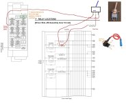
I think I will go add a switch besides the power-inverter switch, you will get 2 choices:
1) back to original configuration, when IGN, power outlets (rear 12V) will be ON
2) power outlets always ON even when the car IGN is off

Please let me know if this is clear enough.

I may go fancy and find a nicer switch later.
 

Attachments

  • 5thgen_power_outlet_switch_mod.jpg
    5thgen_power_outlet_switch_mod.jpg
    115.6 KB · Views: 2,800
OK (after my coffee and on my drive to work), I figured it out, it's similar but definitely not the same mod.

[MENTION=65614]Antman[/MENTION] 's post: http://www.toyota-4runner.org/5th-gen-t4rs/92013-antmans-thread-4.html#post813424 is to use the wire-tap to sneak out 12V constant ON power, and provide that directly to the front cigarette lighter power socket (or any socket); with the flip on the switch, get it back to original factory config.

[MENTION=65398]Reata[/MENTION] 's post: http://www.toyota-4runner.org/5th-gen-t4rs/87848-reatas-build-thread-2.html#post787111 is to run a wire all the way from the battery to the rear (and even add an "always HOT" cigarette lighter power socket); IMO, this is WAY too much work, IF I don't have to do it (depending on how successful is my suggested mod is)

Now, the mod I suggested in http://www.toyota-4runner.org/5th-gen-t4rs/87986-12v-constant-switched-power-2.html#post1948004 allows EVERYTHING that is covered by 15A P/OUTLET fuse to be have constant ON power with the flip of the switch. Unfortunately I do not have the 2014/2015 electrical wiring diagrams, so I cannot confirm (until I actually have time to probe around), what are exactly covered with this particular fuse.

This mod should let me avoid the need to run the front-to-back wire, which I consider "lots of work" if I don't need to do it.

Let me execute on this mod first, if it is as useful as I thought it would be, I may consider putting together a simple plug&play kit group-buy for our members.

PS. does anyone have a list of the "EVERYTHING" cover by the 15A P/OUTLET fuse on 2014/2015?

 
Last edited:
Someone will probably post this before I get a chance to get out to mine, but- I remember seeing a few unused blanks in the fusebox under the drivers dash that were + 12v all the time. Just plug in a mini-fuse tap and run the wire to the lighters. The grounds are white wires with black stripes, and the hot sides that I have seen are green (haven't checked them all). You can leave the ground alone, cut the hot and hookup the new power wire with a butt connector. Make sure you insulate the loose wire end, or you will get a short. I will check back when I get a chance to update if needed!

This is a dangerous idea if you're going to run "factory" current (ie, 10 amps).
I'd never run anything off a mini-tap that uses more than 1 amp or so, unless you've investigated thoroughly to see what the wiring is like to that part of the fuse block and what the circuit is designed for.

You're better off running a full pair of correct gauge AWG fused directly to the battery and either adding a new 12v outlet where you want it or replacing the factory wiring to an existing one (ie, remove factory 12v wiring from socket/tape off)
 
#1:
You're better off running a direct wire to the battery fused. You'll have larger gauge wire the entire length, less voltage drop, no worries about "connector failure" due to heat from the draw from a refrigerator.

#2:
Depending on the current pull, you could go with Antman's mini-tap suggestion. I'd stay under 1 or 2 amps for any mini-tap solutions. Run the wiring directly to this solution and make sure the mini-tap fuse is appropriately sized (1-2 amps)

#3:
Same as #2, you could do a mini-tap for this, keeping the current required low. A good vehicle charger for a cell phone shouldnt consume more than 2-3 amps at 5 volts (or 1-2 amps at 12v, for a switching type, not a cheap linear type)

Well, first of all, I plan on doing a dual battery setup in the near future, so it would allow me to run accessories off of one battery at all times while camping or working out of my truck without having the key in the ignition.

Specifically, I'd like it on a switch for a few things:

1. I have a refrigerator in my truck which I would like to stay-on when I have the truck parked without having to leave it on ACC (i.e while filling the gas tank, camping, etc).

2. I have a vehicle "blackbox" which is essentially just a dual channel (in-cab and dash view) geo-rectified DVR with gyros. So, at a certain G-rating on X, Y, or Z it will record as an "event" on an SD card and mark the video 15 seconds before and 60 seconds after the "event". It also records at all times and overwrites itself after the SD card is full. So, I'd like to be able to leave it recording in certain situations since I live in the DC metro area...

3. For the normal incidental stuff like being able to charge my phone (or other device) without having to have my key in the ignition.

Does that make sense?
 
I want to do it to the 12v outlet on the storage area so you don't need the ignition "on" to have power to run, say an inflator for an air mattress, etc. Why, you want to do another writeup???

I wonder what the current draw is on said inflator, but generally, you should have the vehicle ON with anything drawing significant current. You aren't necessarily in danger of depleting the battery, however, with the vehicle off you'll have significantly lower operating voltage (2-3 volts easily under load) which causes an equivalent increase in current required by that inflator/compressor motor. Increased current means increased heat, you can bake those connectors.

Say you use a 50 watt compressor
Vehicle off:
50 watts = 12 volts * X amps
50/12 = 4.17 amps
Vehicle on:
50 watts = 14.4 volts * X amps
50/14.4 = 3.4 amps

Connectors and wiring have a specific resistance, related to wire length, gauge, etc. To make matters worse, as wire/connectors heat up, their resistance increases. Higher resistance means higher voltage drop, which means the motor driving the compressor will require more current again to run. This is a downward spiral.

Sorry to go off on such a tangent, I'm sensitive to the thought of my vehicle wiring catching fire :)
 
It would be really neat to find the signal wire that flips the relays to enable the 12v sockets. Then you could add a signal wire switch to flip between factory and "always on" very simply. My guess is there isn't a single signal wire that does this, instead, the the sockets are powered when the main accessory bus is ON in the fuse block.

So you're probably looking for the holy grail. I've already posted several times about how a 15A fuse addition on a mini-tap is a terrible idea. The right way to handle this is to wire your own cables direct to the battery and fuse them there. I've done this in pretty much every vehicle I've owned (for various reasons, ham/cb radios, etc). It's really *not* that big of a deal, and it's the right way to do this. Just use quality cable with the right AWG for the current you plan to run through it.

For low-current (1-2 Amps max) a mini-tap is probably OK. Just make sure you use a small fuse on it. For 15A, no way in hell. If toyota put a 25A in a socket, that doesn't mean you can add 15A on top of that and expect it to be OK. That's insane.

OK (after my coffee and on my drive to work), I figured it out, it's similar but definitely not the same mod.

[MENTION=65614]Antman[/MENTION] 's post: http://www.toyota-4runner.org/5th-gen-t4rs/92013-antmans-thread-4.html#post813424 is to use the wire-tap to sneak out 12V constant ON power, and provide that directly to the front cigarette lighter power socket (or any socket); with the flip on the switch, get it back to original factory config.

[MENTION=65398]Reata[/MENTION] 's post: http://www.toyota-4runner.org/5th-gen-t4rs/87848-reatas-build-thread-2.html#post787111 is to run a wire all the way from the battery to the rear (and even add an "always HOT" cigarette lighter power socket); IMO, this is WAY too much work, IF I don't have to do it (depending on how successful is my suggested mod is)

Now, the mod I suggested in http://www.toyota-4runner.org/5th-gen-t4rs/87986-12v-constant-switched-power-2.html#post1948004 allows EVERYTHING that is covered by 15A P/OUTLET fuse to be have constant ON power with the flip of the switch. Unfortunately I do not have the 2014/2015 electrical wiring diagrams, so I cannot confirm (until I actually have time to probe around), what are exactly covered with this particular fuse.

This mod should let me avoid the need to run the front-to-back wire, which I consider "lots of work" if I don't need to do it.

Let me execute on this mod first, if it is as useful as I thought it would be, I may consider putting together a simple plug&play kit group-buy for our members.

PS. does anyone have a list of the "EVERYTHING" cover by the 15A P/OUTLET fuse on 2014/2015?
 
Really?

I'm not sure why you are quoting posts from me that are almost 4 years old. All of these mods have been done, are used almost every day and were done safely. Check out my build thread and you can see for yourself.

I really do not need a lesson on basic automotive electrical work, but thanks anyway. :tea:
 
[MENTION=121437]gunkl[/MENTION], [MENTION=65614]Antman[/MENTION] is good on the electrics, but maybe you can teach him how to fish?
 
Well, first of all, I plan on doing a dual battery setup in the near future, so it would allow me to run accessories off of one battery at all times while camping or working out of my truck without having the key in the ignition.

Specifically, I'd like it on a switch for a few things:

1. I have a refrigerator in my truck which I would like to stay-on when I have the truck parked without having to leave it on ACC (i.e while filling the gas tank, camping, etc).

2. I have a vehicle "blackbox" which is essentially just a dual channel (in-cab and dash view) geo-rectified DVR with gyros. So, at a certain G-rating on X, Y, or Z it will record as an "event" on an SD card and mark the video 15 seconds before and 60 seconds after the "event". It also records at all times and overwrites itself after the SD card is full. So, I'd like to be able to leave it recording in certain situations since I live in the DC metro area...

3. For the normal incidental stuff like being able to charge my phone (or other device) without having to have my key in the ignition.

Does that make sense?

Well if you want a dual battery setup you are going to have to wire the accessories you want run off the second battery independent of the existing wiring anyway. So you could wire them into a distribution block now fed off the existing battery and then swap it when you move to duals
 
Cool, glad they work for you.

I certainly could use a fishing lesson, do you know how to fish?

Really?

I'm not sure why you are quoting posts from me that are almost 4 years old. All of these mods have been done, are used almost every day and were done safely. Check out my build thread and you can see for yourself.

I really do not need a lesson on basic automotive electrical work, but thanks anyway. :tea:
 
It would be really neat to find the signal wire that flips the relays to enable the 12v sockets. Then you could add a signal wire switch to flip between factory and "always on" very simply. My guess is there isn't a single signal wire that does this, instead, the the sockets are powered when the main accessory bus is ON in the fuse block.

Do you have/study up the electrical wiring diagram? That signal is inside the Driver side J/B Assembly/ECU. What I am suggesting in my mod is basically by passing that (as Toyota decided to seal up 5th gen's relays inside this ECU/junctionbox).

So you're probably looking for the holy grail. I've already posted several times about how a 15A fuse addition on a mini-tap is a terrible idea. The right way to handle this is to wire your own cables direct to the battery and fuse them there. I've done this in pretty much every vehicle I've owned (for various reasons, ham/cb radios, etc). It's really *not* that big of a deal, and it's the right way to do this. Just use quality cable with the right AWG for the current you plan to run through it.

I will go measure up the wire gauge and resistance once I get some of these parts in. I am disagreeing with you regarding the mini-tap. The mini-fuse and mini-fuse pin can totally handle the current, and the "wire" that jump from 1 mini-fuse pin to the other will be no less conductive than the wires behind the fuse-box, and the length is short (hence resistance low).

For low-current (1-2 Amps max) a mini-tap is probably OK. Just make sure you use a small fuse on it. For 15A, no way in hell. If toyota put a 25A in a socket, that doesn't mean you can add 15A on top of that and expect it to be OK. That's insane.

Look at my diagram again, and look at all the other associated diagrams within the EWD. The circuit that I am tapping into and hacking is a 15A circuit, and the circuit supports that rating (and with lots of de-rating margin too!)

BTW, [MENTION=65614]Antman[/MENTION] 's mod are solid and have no issues. Good to go! I am just putting something a little different on the table.
 

Members online

Forum statistics

Threads
278,316
Messages
3,554,111
Members
248,016
Latest member
Advally Service

Trending content

Back
Top