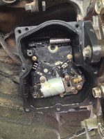
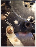
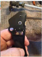
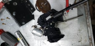
4lo Actuator Rebuild

First up is the greased electrical tape on the shafts. Then we need to slide the shafts into the seals (no snickering). The tape method worked really well.

At this point I removed the tape on the rear shaft and set up the electrical circuit to actuate the 4lo motor, which slid the actuator closer to the t-case. (I failed to take a pic of my set up, so just imagine a lot of speaker wire hooked to the battery)

With the actuator bolted on, I reinstalled the last three gears and the center diff lock indicator, and the cover plate.

Results: It works! Well sort of. I noticed that bolting the actuator to the t-case seems to bind the gears in the actuator some how. I am still tinkering with it, but the motors do spin the lights do light on the dash.
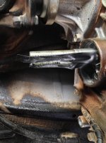
 

Attachments

  • IMG_1706.jpg
    IMG_1706.jpg
    130 KB · Views: 4,014
  • IMG_1708.jpg
    IMG_1708.jpg
    128.9 KB · Views: 3,661
  • IMG_1710.jpg
    IMG_1710.jpg
    134.6 KB · Views: 3,963
  • IMG_1712.jpg
    IMG_1712.jpg
    134.1 KB · Views: 3,505
Hey, excellent info! This may be a little beyond my abilities, but at least I'd know where to start if I ever have a problem.
Looking at how corroded your internals were makes me wonder 1) did that 4runner ever sit in water for a period of time and 2) wonder what mine looks like inside.
So, I'd like to INSPECT mine which leads me to: How is the cover sealed to the case? Can I simply remove & replace it after inspection or will I need to source a new seal for it?
 
Hey, excellent info! This may be a little beyond my abilities, but at least I'd know where to start if I ever have a problem.
Looking at how corroded your internals were makes me wonder 1) did that 4runner ever sit in water for a period of time and 2) wonder what mine looks like inside.
So, I'd like to INSPECT mine which leads me to: How is the cover sealed to the case? Can I simply remove & replace it after inspection or will I need to source a new seal for it?

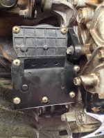
As can be seen in the pictures, there is a a rubber seal recessed in the housing that contacts the outer cover. I am not sure where to get the new seal since these things are "unserviceable". If it were me, I would remove the cover, inspect, then put a light film of say K&N air filter sealing grease or something similar on the recessed seal to help ensure things stay out.

I just bought this rig and I would guess that it did see a few creeks or something similar, causing all the rust, not 100% sure though.
 
Thanks for doing such an informative and intrepid rebuild! It's nice to put an image with the countless 'frozen actuator' stories and knowing that at least some can be rebuilt at relatively low cost is reassuring.

Please let us know if you figure out the binding issue and if the fix stands the test of time.

I see you connected the wiring and did the 4LO actuator BEFORE bolting it up. Just curious as to why it was done in that order? Could the actuator being pulled closer and then bolting it have torqued the gears together and bound them? I have no experience with the actuator/transfer case internals but that stood out to me.

:thumb3: Awesome job on the rebuild
 
I totally expected SOMEONE would have the nads to venture into this.

BTW, in case the link to the electric motors one day goes bad, these are what the OP went with:

PKG(2) 12VDC Reversible 2400 Rpm Mabuchi Motor RS-385PH

Product Features
  • This cutie from Mabuchi is a 12VDC reversible motor that spins at approx 2400 rpm, draws about 17mA no load, and stalls at 240mA.
  • Measures 1-1/2" long x 1-1/16" dia with a removable sleeve. The 3/32" dia x 5/16" long shaft has a removable 5/16" dia single-sheave pulley.
  • Has 9" leads with a 2-pin Molex connector.

[MENTION=100188]Woodless[/MENTION], so far, awesome job!! Keep us updated!!

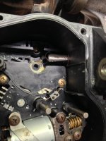
From what I see in the pictures, parts of where the electric motor is located is severely corroded. Looks as though a seal went bad and let moisture/water in. Maybe this is why some of our actuators go bad???
 
I totally expected SOMEONE would have the nads to venture into this.

BTW, in case the link to the electric motors one day goes bad, these are what the OP went with:

PKG(2) 12VDC Reversible 2400 Rpm Mabuchi Motor RS-385PH

Product Features
  • This cutie from Mabuchi is a 12VDC reversible motor that spins at approx 2400 rpm, draws about 17mA no load, and stalls at 240mA.
  • Measures 1-1/2" long x 1-1/16" dia with a removable sleeve. The 3/32" dia x 5/16" long shaft has a removable 5/16" dia single-sheave pulley.
  • Has 9" leads with a 2-pin Molex connector.

[MENTION=100188]Woodless[/MENTION], so far, awesome job!! Keep us updated!!

From what I see in the pictures, parts of where the electric motor is located is severely corroded. Looks as though a seal went bad and let moisture/water in. Maybe this is why some of our actuators go bad???


I think that's the motor that came in the old Grasshopper RC cars, LOL.
Seriously though, that level of corrosion is pretty nasty. How's the rest of the frame and suspension look? I'm just trying to figure out if it's worth popping off that cover and spraying some teflon lube in there or something.
 
Thanks for doing such an informative and intrepid rebuild! It's nice to put an image with the countless 'frozen actuator' stories and knowing that at least some can be rebuilt at relatively low cost is reassuring.

Please let us know if you figure out the binding issue and if the fix stands the test of time.

I see you connected the wiring and did the 4LO actuator BEFORE bolting it up. Just curious as to why it was done in that order? Could the actuator being pulled closer and then bolting it have torqued the gears together and bound them? I have no experience with the actuator/transfer case internals but that stood out to me.

:thumb3: Awesome job on the rebuild

Thank you for the compliments.

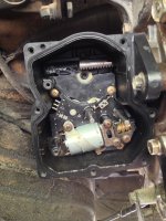
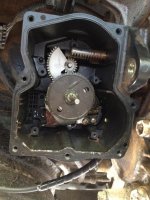
I had to power up the 4lo motor in order to "suck" the actuator onto the 4lo shaft, otherwise it is impossible to install it. Take a look at the first attached pic, see the funky looking "half moon" gear? Now take note of the two shafts, one is contacting the center gear on the half moon gear and the other shaft, the center diff shaft, is not contacting anything.

Now look at the second attached pic, see how the half moon gear is no longer visible? That is because the plate that holds the center diff motor and gearing is installed in this pic, however, one cannot push/maneuver that plate past that center diff shaft.

This being said, you have to power up the 4lo motor to help suck the actuator onto the shaft, once all the way on, secure a couple threads on the attaching bolts then reverse the motor shoving the shaft back into the t-case. I found it nice to leave the three gears for the center diff off so I could keep an eye on the timing marks.

I hope this helps, I think I should have done a video instead though.
 

Attachments

  • IMG_1667.jpg
    IMG_1667.jpg
    135.6 KB · Views: 3,412
  • IMG_1710.jpg
    IMG_1710.jpg
    131.5 KB · Views: 4,129
I totally expected SOMEONE would have the nads to venture into this.

BTW, in case the link to the electric motors one day goes bad, these are what the OP went with:

PKG(2) 12VDC Reversible 2400 Rpm Mabuchi Motor RS-385PH

Product Features
  • This cutie from Mabuchi is a 12VDC reversible motor that spins at approx 2400 rpm, draws about 17mA no load, and stalls at 240mA.
  • Measures 1-1/2" long x 1-1/16" dia with a removable sleeve. The 3/32" dia x 5/16" long shaft has a removable 5/16" dia single-sheave pulley.
  • Has 9" leads with a 2-pin Molex connector.

[MENTION=100188]Woodless[/MENTION], so far, awesome job!! Keep us updated!!

From what I see in the pictures, parts of where the electric motor is located is severely corroded. Looks as though a seal went bad and let moisture/water in. Maybe this is why some of our actuators go bad???

Well, my first name is Dan and Dan spelt backward is nad, so I guess I was right for the job? lol

Popping off that cover and taking a look at the internals would not hurt IMHO.
 
I think that's the motor that came in the old Grasshopper RC cars, LOL.
Seriously though, that level of corrosion is pretty nasty. How's the rest of the frame and suspension look? I'm just trying to figure out if it's worth popping off that cover and spraying some teflon lube in there or something.

The rest of the runner is in awesome condition, I really cant complain. I do wonder if maybe some ATF seeped by and helped the corrosion?
 
Thanks for clarifying the install process - the pics definitely helped. Let us know how the binding issue works out.
 
Hello

Does any know how to time this thing?
In what position are the 2 rods (all the way out or in) and what position the sensors are set at?

I see there are lines that point to a notch but have no idea where to put rods.

Thanks in advance
Dan
 
Did this project ever succeed?

I am curious if Dan was ever able to get his working again. I started tearing mine apart before reading this thread. Gears fell out. Pretty sure I reinstalled wrong because now all lights are blinking (green 4wd, yellow 4wd, TRAC off) and 4hi no longer works. :(

I was hoping to avoid the dealer costs, but now I may have backed myself into a corner (winter is coming).
 
I am curious if Dan was ever able to get his working again. I started tearing mine apart before reading this thread. Gears fell out. Pretty sure I reinstalled wrong because now all lights are blinking (green 4wd, yellow 4wd, TRAC off) and 4hi no longer works. :(

I was hoping to avoid the dealer costs, but now I may have backed myself into a corner (winter is coming).
Did you fix this? If not I should have some pics on my PC showing correct position of the gears.

I assembled mine a few times, nothing too difficult.
 
Did you fix this? If not I should have some pics on my PC showing correct position of the gears.

I assembled mine a few times, nothing too difficult.
If you have some pics that would be great. Maybe I could rebuild my old actuator. I bought a complete transfer case/actuator assembly from a wrecked vehicle on eBay. Cost $850, but it worked perfectly. I learned how to easily test the actuator/transfer case assembly without installing on the vehicle. so maybe I could fix this actuator and keep as a spare.
 
Bringing an old thread back to life!

I'm in the middle of doing the timing of the CDL & hi/lo actuator and wanted to know what do the two timing mark should look like before I button everything up.

The Hi/Lo should be in Hi mode as selected by the selector switch in the dash. I have a full time Tcase and I know the position of the shift rod on the Tcase during 4Hi mode.

The CDL should be unlocked since that was the position of the push button before I dropped the Tcase. I know the position of the shift rod on the Tcase for the CDL to be in the unlocked position.

Incidentally, the CDL shift rod basically brings in the front DS in/out of the picture. So, this exercise made me think that this full time Tcase is sorta acting like a part time Tcase.

Attached are the two pics that I saw earlier in this thread but I'm not sure the indicators are sitting at the final position before reassembly. Final position being the CDL is unlocked (or 2 wd) and the tcase is in Hi position (or 4high).

Thanks.
 

Attachments

  • CDL gear 1.JPG
    CDL gear 1.JPG
    71.9 KB · Views: 1,056
  • CDL gear 2.JPG
    CDL gear 2.JPG
    72.1 KB · Views: 1,032
Was there a trick in removing the top motor mount? Mine won't budge after removing all of the mounting screws and I need to get to the 4H/L motor.

Yes there is. I just put mine back together for round one of testing so this nightmare is fresh in my mind. You *may* have to remove the top motor before able to remove the top plate. Again, this is still a guess and I'll know once I take things apart for re-timing today. I had to solder the motor back in before buttoning her up last night and everything worked but the Low indicator light wouldn't go off.

But first, I'll disconnect the battery and reset the ECU just for S&G.
 

Attachments

  • CDL top motor removed.jpg
    CDL top motor removed.jpg
    142.4 KB · Views: 1,013
Yes there is. I just put mine back together for round one of testing so this nightmare is fresh in my mind. You *may* have to remove the top motor before able to remove the top plate. Again, this is still a guess and I'll know once I take things apart for re-timing today. I had to solder the motor back in before buttoning her up last night and everything worked but the Low indicator light wouldn't go off.

But first, I'll disconnect the battery and reset the ECU just for S&G.

If you did not have to remove the actuator housing to get to the 4H/L motor, that's fantastic news! Looking forward to the update and hoping mine is a poor solder connection. The internals of mine are spotless but I'm stuck in 4LO.
 

Members online

Forum statistics

Threads
278,312
Messages
3,554,089
Members
248,016
Latest member
Advally Service

Trending content

Back
Top