4Runner alternator upgrade (gen 5)

Nice job Rig!

I know how long it takes to make these write-ups, and this one is done well.

I agree 100% with you about the stock alternator being just barely adequate. Now that I have my LED battery monitors installed I have made note of just how often the stock alternator can't keep up with the demand. My LED lights up green whenever the alternator is charging, and orange when less than 12.8V is detected. Surprisingly, if the fan is on the 3rd or 4th setting the LED will usually glow orange at idle. If my 12V Cooler is running for a while (draws up to 5a) forget it! The stock alternator is overworked for sure on a modified truck.
If you don't mind me asking, how much is that alternator, or did I miss that?
 
Hi team,

I'd just like to thank all who have taken the time to read, and reply to this thread; your views and your comments are very much appreciated! There is a video (several videos that are available) circulating which are very informative regarding this company "DC Power Engineering" who is building these "Denso hairpin" large case alternators. A lot of companies are "Hot-Rodding" the denso small case, using the Japanese platform as a base and then attempting to 'over-wind' the stator and rotor so it will crank out 180 or 200 amps. Problem is that the platform was only designed to generate 130 amps or so. What happens as a result is, these hot-rods can't get rid of the heat (the by product of generating electricity via 'induction') and so these alternators can't hold up when pushed.

The denso hairpin large case is only called that because that is a brillant format that has been used by the company 'Denso'. But the 'large case is a whole different animal when examined and analysed properly! The end frames (casing) are a massively efficient heatsink to start with. It was built to support the over-wound coils which are the stator and rotors. Instead of using 6 diodes in their design, they use 12 diodes that are pressed into the massive heat conductor, and not one cooling fan, but two are used; one in front and one in the rear, helping things to stay cool. "Here's a couple of videos that I think you'll find interesting" at least:
https://www.youtube.com/watch?v=ZWL85x3JVzc

https://www.youtube.com/watch?v=zvVn1The8gs

Toyota 4.0L V6 1GR-FE 270A Alternator Tacoma,4Runner,FJ Cruiser DC Power Alternator

https://www.dcpowerinc.com/info/xp-hp-series-high-output-alternators.html

This one (below) is not the coveted XP series alternator, but it does show the the machining process used to manufacture these alternators; check it out!
https://www.youtube.com/watch?v=SSILASmW-mg

...And I've got plenty more where that came from! Hahaha enjoy!

PS: Just a note (slightly off topic). Last week I posted a thread regarding a "Party mode tweak" (an audio system mod). Well I goofed a little because when I submitted it, there was something wrong with the new photo album that I had created just for that thread. I could see the photo submissions I posted, but I didn't know that you were unable to see them; and this thread was somewhat involved, so you needed pictures just to make sense of what I was doing. Well a few helped out and brought it to my attn, so I posted all of the photos again so you could see them and maybe benefit from this thread... "The party mode tweak"... see link below: http://www.toyota-4runner.org/5th-gen-t4rs/171794-party-mode-tweak-non-jbl.html

Hope you will enjoy this tread! chow!
 
Last edited:
Nice job Rig!

I know how long it takes to make these write-ups, and this one is done well.

I agree 100% with you about the stock alternator being just barely adequate. Now that I have my LED battery monitors installed I have made note of just how often the stock alternator can't keep up with the demand. My LED lights up green whenever the alternator is charging, and orange when less than 12.8V is detected. Surprisingly, if the fan is on the 3rd or 4th setting the LED will usually glow orange at idle. If my 12V Cooler is running for a while (draws up to 5a) forget it! The stock alternator is overworked for sure on a modified truck.
If you don't mind me asking, how much is that alternator, or did I miss that?

Hi Jeff,

I think I may have spent around 600-$650 for mine, and they are 'special ordered; mine took about two months to get here. Now here's the thing. There are a lot of supped-up 'small hairpins' going around that can be had for 2 to $250 bucks. They look just like the large case, heck there even making um chrome and putting fins on them so they look the part. But as you know, it's what's on the inside that makes it work; so you gotta be careful. The big difference is, the "Impostors" will not tolerate being asked to develop 200 amps at curbside idle, and that's where it really counts; when you're sitting still. Just think, you never have to tap the gas or rev the engine to charge the battery, neither will the lights start to dim just because you're sitting still... never! I think "Prado" is asking $700 for theirs (that's the Canadian DC Power eng'r affiliate), Here's a link to a thread (By BlackWorksInc) where this very subject was being discussed not too long ago, really interesting read: http://www.toyota-4runner.org/4th-g...ality-hi-output-alternator-options-there.html

I like what you said about your gauges/meters. You can actually see when the O.E.M. charging system starts to take a dive, and right to the line where 4 to 5 amps makes a critical difference! WOW! We are just on the borderline! Toyota is very smart. Not only did they calculate exactly how much alternator to give (sell) us, they also calculated just how small the wire size they could get away with; and not one copper strand extra. I didn't measure them, but I think those oem battery to fender cables may just be #8awg. I was comparing them to the 4ga cables I used to feed my power amps, and I had to pull two of those to feed them; one for each, so toyota really played it close.

Hey Jeff, thanks for your post, I really do appreciate that! Best to you!

Greg
 
Hey Antman'

You've got me curious. In one statement you said:
"I have made note of just how often the stock alternator can't keep up with the demand. My LED lights up green whenever the alternator is charging and orange when less than 12.8v is detected."

Are your LED battery monitors able to distinguish (interpret) between when the battery voltage is reading low because the temperature outside is way below freezing (5 deg), from when the voltage is reading low because the alternator is overloaded?

Also... can you tell just how much amperage (numeric values) the alternator is delivering at any time (like while driving), or is it just when you're stationary and performing a test? One more question. If the blower 'ramps up' because of auto temperature control, or the fridge comes on and the led monitor goes to orange, can you compensate with increased rpm, or is it necessary to start shutting stuff down at that point? That's a nice system, just trying to figure out how it's set up.

rigtec, cheers
 
Dang....got me some learning today! Great write up and also appreciate some of the replies from others in the know as well. Been doing my own build lately but definitely need to really think about this; I seee another mod on my list. Great article and thanks for sharing! :cheers:
 
Dang....got me some learning today! Great write up and also appreciate some of the replies from others in the know as well. Been doing my own build lately but definitely need to really think about this; I seee another mod on my list. Great article and thanks for sharing! :cheers:

Hi Desert Dawg,

Thank you very much for your comments! It's always nice to know after you've spent quite a few hours drafting a composition that someone may find it to be useful or interesting to read. I see that you've only been here since March, and already you're finding your way around the forum like you have been here forever! I'm liking the new Trail w/KDSS, and you've done a number of mods already, hope you'll be sharing those mods with us at some point; w/pics! :thumb3: Happy trails!

rigtec, cheers
 
Hi Desert Dawg,

Thank you very much for your comments! It's always nice to know after you've spent quite a few hours drafting a composition that someone may find it to be useful or interesting to read. I see that you've only been here since March, and already you're finding your way around the forum like you have been here forever! I'm liking the new Trail w/KDSS, and you've done a number of mods already, hope you'll be sharing those mods with us at some point; w/pics! :thumb3: Happy trails!

rigtec, cheers


Thanks rigtec! I try to do the same in case in helps someone (or not...lol), so really appreciated your post.

I have been posting about my build, so if you ever get really, really bored you can take a look. Might be good for some "right before" bedtime reading...lol. :sleepy:

http://www.toyota-4runner.org/5th-gen-t4rs/168993-desert-dawg-build-what-switch.html
 
Hi 1Eng'r

Thanks so much for your generosity and kind words, they are much appreciated! Your electrical engineer colleague would appear to be 'wise on an epic scale'; I've never heard any theoretical principle, phrased so eloquently; very much poetic!

Greg (rig)

You should put that quote in your signature. So I have a few questions for you rigtec.

1. In the instance where I hear about people adding 2 batteries to their truck to provide power supply to their additional electrical components, is this not a good idea? I mean, sensibly it would just continually drain the battery where as having an alternator would provide "belt driven" electicity. I know energy cannot be self created but in this instance it almost is, isn't it?

2. If someone were to perform this upgrade pre-emptively, just to have this "power-plant" available for future use, is this the best way for someone whose never done this to do so?
 
Hey Antman'

You've got me curious. In one statement you said:

Are your LED battery monitors able to distinguish (interpret) between when the battery voltage is reading low because the temperature outside is way below freezing (5 deg), from when the voltage is reading low because the alternator is overloaded?

Also... can you tell just how much amperage (numeric values) the alternator is delivering at any time (like while driving), or is it just when you're stationary and performing a test? One more question. If the blower 'ramps up' because of auto temperature control, or the fridge comes on and the led monitor goes to orange, can you compensate with increased rpm, or is it necessary to start shutting stuff down at that point? That's a nice system, just trying to figure out how it's set up.

rigtec, cheers

Basically the LED's use different colors/flashes to communicate voltage only, nothing to do with amps or temp.

Here's the link and the chart that shows the available settings...
6V 12V 24V Programmable LED Battery Level Voltage Monitor Meter Indicator J | eBay

They can be set to operate on one of 6 programmable 'maps'. I have my main battery LED set to map #2 which will show orange anytime the voltage delivered is 12.8-11.8 (voltage is typically higher in a charging situation). If the voltage goes below that it blinks yellow, then red, etc. I was surprised because the LED often goes orange while at idle with even factory accessories on (seat heaters, high fan speed, etc). The light goes back to green immediately with even the slightest throttle though.

The auxiliary battery LED is set to map#3 which also shows a charging condition as green, but then blinks to show status below 12.8v - this is extremely low amp draw mode to conserve the battery for emergency use.

They also make a cigarette lighter version for someone that doesn't want to cut a hole anywhere...
 
"... So I have a few questions for you rigtec.

1. In the instance where I hear about people adding 2 batteries to their truck to provide power supply to their additional electrical components, is this not a good idea? I mean, sensibly it would just continually drain the battery where as having an alternator would provide "belt driven" electicity. I know energy cannot be self created but in this instance it almost is, isn't it?

The two methods of achieving more amperage (current) capacity are for two different reasons.

(1) A "Dual battery set-up" applies to an environment where there may not be any available electricity (like camping) an so the truck becomes that source of power which may provide lights, fridge, music, tv, etc...

Most who use this method will install a selector switch example: batt A, batt B, or batt A & B. This way, they can use the auxiliary battery to operate all of their accessories and never jeopardize the truck's main power source and risk needing a jump start when they're alone, way out in the wilderness.

(2) The "High output alternator" application is completely different. This is mainly used when a large current demand will be imposed on the truck's electrical system during a time when the truck is in use, and will provide the power for something other than normal driving e.g., winching, high current auxiliary lighting set-ups, or in my case, high consumption power amp loads.

2. If someone were to perform this upgrade pre-emptively, just to have this "power-plant" available for future use, is this the best way for someone whose never done this to do so?

As they say: "there's a first time for everything"! I'll assume you referring to a larger alternator... Sure, if you're planning to modify your machine and you have an idea of what you may do to it, you can certainly begin choosing the components best suited for the task, based on what you plan to do up the road. For instance, if you want to add a good amount of lighting to the truck, you could total the predicted amount of current they will need (full load) to operate and then decide on the approx size alternator needed to support it; and (imho) you should always over estimate the amount of power you believe you will need (a built-in safety margin)... just in case! hope I answered your question(s) best to you!
 
"...I know energy cannot be self created but in this instance it almost is, isn't it?"

"Almost missed this part of your comments",

You're right. We do not create energy, we can only change the form or state in which it was found. There are two different methods in which we have charged our car's batteries across time. The first was with the use of a generator. The generator uses a 'fixed' natural magnet (ceramic or metal). By turning or spinning this magnet in close proximity of a copper coil built in to the frame, the magnetic field adjacent to the coil generated a current within the coil itself, and so provided a marginal amount of electricity to operate the car.

Now with an alternator, it's done a little differently; same principle. Instead of using a 'fixed' natural magnet, which was cost prohibitive, we now use what's known as an alternator. This alternator, instead of a fixed magnet, uses a rotor. The rotor has a copper coil which is connected to a power source (our 12v battery), at which time develops or creates a magnetic field, just like the natural magnet does. It also uses a 'stator': a series of copper coils (3 or 6) tightly wound in bundles forming a group. When our rotor is spun at a high rpm, and placed in close proximity (thousandths of an inch) of the stator, the magnetic field created by the 'now energized' rotor coil, will generate an electric current (in the stator) much higher than the small amount of current used to energize the rotor. The faster the rotor is spun, the higher the voltage output to the vehical, so a voltage regulator had to be implemented, in series w/ the rotor circuit. By limiting the magnetic field created by the rotor, we are also able to control just how much voltage will be generated by the stator, thus setting a safe limit to it's voltage output. That's the basics!

So you're absolutely correct, we can't create energy! PS: Your comments and questions are extremely intelligent and well thought through. Please continue posting your observations on the forum, many others will benefit!

Hope I answered your question(s) best to you!
 
Last edited:
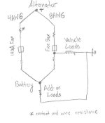
The "Tandem Supply Cable" idea is interesting, I wonder how well it works out in the end? Theoretically electricity will take the path of least resistance, so the larger gauge cables should end up being used by the vehicle more than the factory wiring if wired in parallel as they should have the lowest resistance in the circuit. So while the potential voltage is going to be the same in your circuit, amperage flow will most likely be uneven with a bias towards the lowest resistance cable/path (if I remember my parallel circuits right of course, its a bit fuzzy.) Of course that's just theory, in practice its probably a little different. I don't know if it will effectively split the loads and thus increase the load capacity as intended; I'd be interested to see what sort of amperage readings you get out of that.

In any case, its a really great write up and I appreciate the mention (by the way adding an @ in front of someone's name "Mentions" them, i.e. [MENTION=83083]rigtec[/MENTION] ), always good to see fellow smarty pants sharing their knowledge! :P
 
Last edited:
The "Tandem Supply Cable" idea is interesting, I wonder how well it works out in the end? Theoretically electricity will take the path of least resistance, so the larger gauge cables should end up being used by the vehicle more than the factory wiring if wired in parallel as they should have the lowest resistance in the circuit. So while the potential voltage is going to be the same in your circuit, amperage flow will most likely be uneven with a bias towards the lowest resistance cable/path (if I remember my parallel circuits right of course, its a bit fuzzy.) Of course that's just theory, in practice its probably a little different. I don't know if it will effectively split the loads and thus increase the load capacity as intended; I'd be interested to see what sort of amperage readings you get out of that.

In any case, its a really great write up and I appreciate the mention (by the way adding an @ in front of someone's name "Mentions" them, i.e. [MENTION=83083]rigtec[/MENTION] ), always good to see fellow smarty pants sharing their knowledge! :P

Hi BlackWorksInc,

And thanks for your comments! I really enjoyed reading your post about those "High output" aftermarket alternators! I'm posting the link here again so others can read that as well; since we're discussing alternators here anyway...
http://www.toyota-4runner.org/4th-g...ality-hi-output-alternator-options-there.html

My objective in adding the secondary cables to the electrical system mains was to minimize the excessive resistance imposed by the borderline capability of the factory's low standard. All of the additional loads that I've added to the vehicle, are on fused, "dedicated line circuits" and pull directly from the battery. The original factory mains are uncompromised in that, what was there is still there; no additional accessories have been installed. My main concern was the small gage wire going back to the battery, particularly the (#8ga ?) ground cables from the left fender to the neg battery terminal... all of the additional equipment had to share that small gage wire, so I'm paralleling there with a tandem cable. The original and added cables are side by side and only a ft and a half long. This is just to minimize the resistance there or I'll get pulsating lights whenever I'm pumping the s%#t out of the subs.

Also, the main positive battery cable, I'm paralleling there as well to assure that no matter what else is demanding current from the truck's main electrical block, the battery can always receive a replenishing charge directly from the alternator. And remember, I don't have any high demand loads placed on the main electrical box; those come straight from the battery, so there should never be a problem w/current flow.

PS: And thanks for the tip about the @ when mentioning someone's name; I'll remember that! cheers! :tea:
 
The only concern I'd have is over time, corrosion can increase the resistance in second parallel line and shunt the majority of the load to the original cable, resulting in a blown main fuse and stranded vehicle. However, any reasonable maintenance will prevent that scenario.
 
The only concern I'd have is over time, corrosion can increase the resistance in second parallel line and shunt the majority of the load to the original cable, resulting in a blown main fuse and stranded vehicle. However, any reasonable maintenance will prevent that scenario.

Hi JeremyB'

I guess you missed what I said about the way I have my accessories wired. Even if the tandem cables weren't there, I'm still not drawing any extra current through the truck's 140A main fuse. That fuse is only doing what Toyota engineers have designed for it to do; it provides power to the truck's factory accessories. The installed 'add-on's draw current directly from the battery, and are on fused, designated line circuits. The larger alternator is there because the stock 130A unit couldn't provide enough current for everything together so it was replaced.

Cheers
 
Basically the LED's use different colors/flashes to communicate voltage only, nothing to do with amps or temp.

I really liked the LED charging system monitor, just a quick glance at it tells the whole story! ...can't believe how small they're making these circuit boards nowadays! :thumb::thumb: Best regards!
 
[MENTION=83083]rigtec[/MENTION] thanks for answering my questions and responding to almost each post with further information and sincerity. This thread is extremely informative and beneficial. I think it should be added to the mod list thread or stickied since at some point in modding a vehicle this is a must do.

More questions to follow, still learning! :D
 
Thank you for all your hard work! This is something I am definitely interested in doing! So thankful for your detailed write up and all the excellent detail!
 
Hi JeremyB'

I guess you missed what I said about the way I have my accessories wired. Even if the tandem cables weren't there, I'm still not drawing any extra current through the truck's 140A main fuse. That fuse is only doing what Toyota engineers have designed for it to do; it provides power to the truck's factory accessories. The installed 'add-on's draw current directly from the battery, and are on fused, designated line circuits. The larger alternator is there because the stock 130A unit couldn't provide enough current for everything together so it was replaced.

Cheers
I didn't miss it. Athough your 'add-on' items are connected to the battery, the power they draw it pulled from the alternator until the alternator is maxed out and voltage drops below 12.6-12.8 (full voltage for a charged battery) - at which point the battery begins to feed power into that line. Power flows from a higher voltage to a lower voltage. Since your fully charged battery sits around 12.6-12.8V, it isn't providing any power until the node voltage drops below that value. Without your added 4AWG cable, you could blow your main fuse.

Also, what I was referring to was is an imbalanced parallel load. If you get corrosion in your 4AWG cable, the resistance can increase to a point where the majority of the load is passed through the 8AWG cable. You can then blow your main fuse. Is it very likely? Not at all, but it is something to think about.
 

Attachments

  • rigtecpowerdiagram1.jpg
    rigtecpowerdiagram1.jpg
    28.1 KB · Views: 1,368
I didn't miss it. Athough your 'add-on' items are connected to the battery, the power they draw it pulled from the alternator until the alternator is maxed out and voltage drops below 12.6-12.8 (full voltage for a charged battery). - at which point the battery begins to feed power into that line...

What...??

I'm sorry, did I give the impression that I began working on electrical systems on Wednsday...

Quite a bit of anticipatory speculation in your post. Your theory, though full of formulas... "and a chart", just doesn't apply. If you get some time take a look at this. The author (JL Audio advisory board staff member) advises the reader/installer to upgrade those inadequate, small factory equipment wires with larger ones (at least 4ga), and suggests leaving those smaller O.E.M. cables in place, "and no mention of any catastrophic, chain destruction phenomena..." Here's the full article link:
https://jlaudio.zendesk.com/entries/21923235-Upgrading-the-Big-3-

PS: If you feel that what I've done here is flawed in some way and won't work, then you need to back your theory up with some hard core (white paper) evidence; and not written w/ a crayon on some bathroom tissue paper; BRING PROOF!

regards!
 

Forum statistics

Threads
278,312
Messages
3,554,089
Members
248,016
Latest member
Advally Service

Trending content

Back
Top