AEM FIC-6 piggyback ECU installation procedure

Johns06yota

Member
This will be a writeup on how to install the AEM fic-6 piggyback ecu unit
for the 1GR-FE engine for the 06-09 model years. This guide may be able
to be loosely followed for the 03-05 as well.

I needed this for my rear mount turbo build to be able to properly adjust timing, fuel, and o2 tables to keep the vehicle performing properly and safely under boost. This could very easily be able to be used in a NA application as well

THIS WILL NOT WORK FOR THE V8 4RUNNERS!!!! THIS UNIT IS ONLY USABLE FOR V6 ENGINES!!!

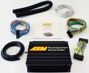
I will break this into multiple parts to keep everything organized. First of all you need the actual unit. The one you need is the:

AEM 30-1910

Any other part number may not work as this is the universal part.


The other parts you need are as follows:

----7.5K OHM resistors
----Quality heat shrink with glue
----A decent soldering iron set
----various screw drivers
----adhesive material for AEM unit
----1/8 vacuum tee 3 way
----1/8 inch vacuum hose


OPTIONAL BUT RECOMMENDED:
----pick tool to de-pin the unused wires
----wire loom tape
----velcro adhesive
----windows computer with the following software installed

F/IC Calibration Software | AEM

(DOWNLOAD THE F/IC-6 FILE)

Simply run the program and it will set itself up. To use the software you must open the calibration file called "Base Cal.fi6"
 

Attachments
  • fic6-complete-kit.jpg
    fic6-complete-kit.jpg
    65.7 KB · Views: 3,222
Last edited:
Register to hide this ad
Step 2

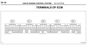
To get started in the vehicle you need to first understand the wiring of the engine PCM. Mine is an 06 but should be the same for the 07, 08, and 09 model years. The first image below shows the pcm connectors. MAKE SURE YOU WATCH THE ORIENTATION TO KEEP TRACK OF WIRES.

At this time no one makes a plug and play harness for this unit for our vehicles. This means that you will be cutting wires to either splice or completely intercept wires.

I AM NOT RESPONSIBLE FOR DAMAGE YOU CAUSE!!!!!


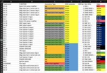
I think I made my point above that you are doing this on your own but this is the guide to help you along the way. Reference the first picture to keep track of the wire location being used. Those are the actual toyota ecu pins.

Next once you have familiarized yourself also reference the second picture showing the actual wiring for everything.

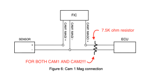
This is where the 7.5K ohm resistors come into play. From research I did toyota has a bad habit of having dirty cam signals therefore throwing a code when a unit like this is hooked up. To fix this a resistor must be used. Reference the third picture to see how this has to be done. THIS MUST BE DONE FOR BOTH CAMS
 

Attachments

  • Screen Shot 2020-01-03 at 10.12.17 PM.jpg
    Screen Shot 2020-01-03 at 10.12.17 PM.jpg
    151.3 KB · Views: 3,202
  • Screen Shot 2020-01-03 at 10.12.50 PM.jpg
    Screen Shot 2020-01-03 at 10.12.50 PM.jpg
    107.3 KB · Views: 3,905
  • Screen Shot 2020-01-03 at 10.21.09 PM.png
    Screen Shot 2020-01-03 at 10.21.09 PM.png
    68.5 KB · Views: 3,515
Last edited:
Step 3

I think it goes without saying that you want to remove the negative terminal on the battery before starting any work. Now once you start wiring pay attention to the above information where it states intercept wire from engine and from ecu. Intercept means you will need to cut the wire so in turn it will give you a wire on the ecu side and one on the engine side or sensor side. Pay attention to which connection goes where. Some of this info is referenced in the manual but sometimes it can be confusing.

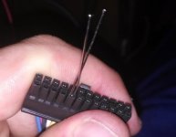
Also at this time you can de-pin wires you no longer need. as seen above there are numerous wires that are not needed. Toyota uses mag style sensors so all the hall wires can be removed along with the other pins not shown above. To do this you can either use a pin tool and press the pin firmly down to pop it out or use paper clips/needles as shown in the guide for the third gen models by @MTD . Either way works and cleans out a lot of unnecessary wires and makes things more manageable

Another thing to do at this time is run your boost reference for the unit. I used a 3 way 1/8 inch barb tee to go from the fuel pressure regulator reference to the unit.

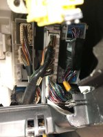
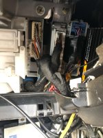
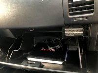
The second picture shows what the ecu connectors look like when you remove the glove box

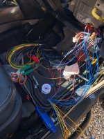
In the third picture you can see that there is a lot of wire but don't get discouraged!

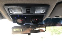
DO NOT FORGET YOU NEED A WIDEBAND GAUGE. the unit pulls info from it to make adjustments to the stock computer. I have an AEM UEGO gauge which has worked flawlessly
 

Attachments

  • Screen Shot 2020-01-03 at 10.31.17 PM.jpg
    Screen Shot 2020-01-03 at 10.31.17 PM.jpg
    54 KB · Views: 2,886
  • IMG_4776 2.jpg
    IMG_4776 2.jpg
    126.4 KB · Views: 3,018
  • IMG_4778.jpg
    IMG_4778.jpg
    137.4 KB · Views: 3,311
  • Screen Shot 2020-01-03 at 10.48.14 PM.jpg
    Screen Shot 2020-01-03 at 10.48.14 PM.jpg
    120.1 KB · Views: 2,814
Last edited:
Step 4

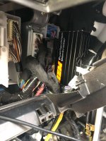
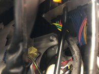
Once you have finalized the wiring which will take several hours. Make sure all your solder connections are strong and that your heat shrink is fully covering anything that had been exposed. You do NOT want any of these wires coming loose as it can cause your vehicle not to run. Now is time for placement. You may find that space is a little tight which it is but there is a spot in the passenger side kickpanel on the sheetmetal where the unit fits. I used adhesive backed velcro to hold the unit in place which makes for easy removal if I ever need to access anything. This is also the time to do wire management and final cleanup. If you wire it properly all the wires will be the same length and all for you to use loom tape to cover and protect everything. This is the route I took any everything looks like it was meant to be there. This is also the time to test that your vehicle turns on and that you have no engine codes.

If so its time to tune!
 

Attachments

  • IMG_4782 2.jpg
    IMG_4782 2.jpg
    130.8 KB · Views: 2,913
  • IMG_4783.jpg
    IMG_4783.jpg
    131.7 KB · Views: 2,928
  • IMG_4784 2.jpg
    IMG_4784 2.jpg
    117.9 KB · Views: 2,812
  • IMG_4785.jpg
    IMG_4785.jpg
    122 KB · Views: 2,753
Last edited:
To get started in the vehicle you need to first understand the wiring of the engine PCM. Mine is an 06 but should be the same for the 07, 08, and 09 model years. The first image below shows the pcm connectors. MAKE SURE YOU WATCH THE ORIENTATION TO KEEP TRACK OF WIRES.

At this time no one makes a plug and play harness for this unit for our vehicles. This means that you will be cutting wires to either splice or completely intercept wires.

I AM NOT RESPONSIBLE FOR DAMAGE YOU CAUSE!!!!!


I think I made my point above that you are doing this on your own but this is the guide to help you along the way. Reference the first picture to keep track of the wire location being used. Those are the actual toyota ecu pins.

Next once you have familiarized yourself also reference the second picture showing the actual wiring for everything.

This is where the 7.5K ohm resistors come into play. From research I did toyota has a bad habit of having dirty cam signals therefore throwing a code when a unit like this is hooked up. To fix this a resistor must be used. Reference the third picture to see how this has to be done. THIS MUST BE DONE FOR BOTH CAMS

Hi, i am having issue with 4 warning lights that dont come on when I key on:
1. Engine Check Light
2. TPMS
3. VSC off
4. Slip light control
5. VSC TRAC

Checked the LEDs they are all good, i even replaced them just in case.

Now ir comes down to wirings from ECU so I would like to know if you can share the whole excel file from above picture?
If you can help point out which pins sepcifically need to be checked that will really be nice.

FYI my car is 2007 v6 sport. thank you
 

Members online

Forum statistics

Threads
278,316
Messages
3,554,110
Members
248,016
Latest member
Advally Service

Trending content

Back
Top