aemravan's build thread - project TacoRunner

So couple of quick notes :

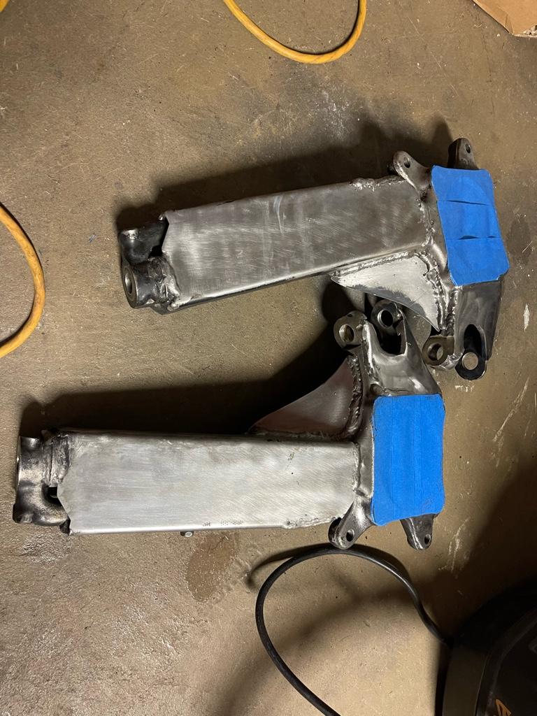
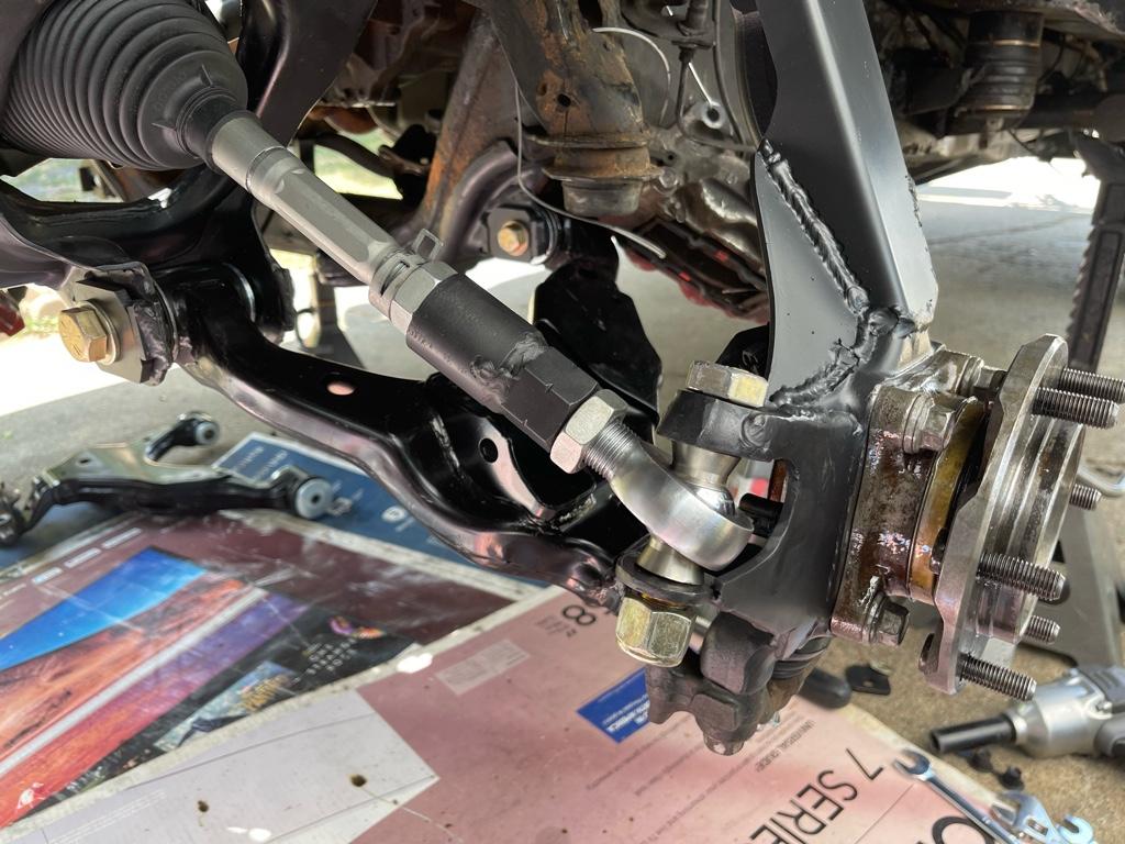
I definitely made the mistake of tightening down on the heims really tight ahead of welding everything in place.. that long with a little warping resulted in needing to beat them into place after. Not a Huge deal, just needs a little grinding.. but was really hoping I could just paint these first thing tomorrow

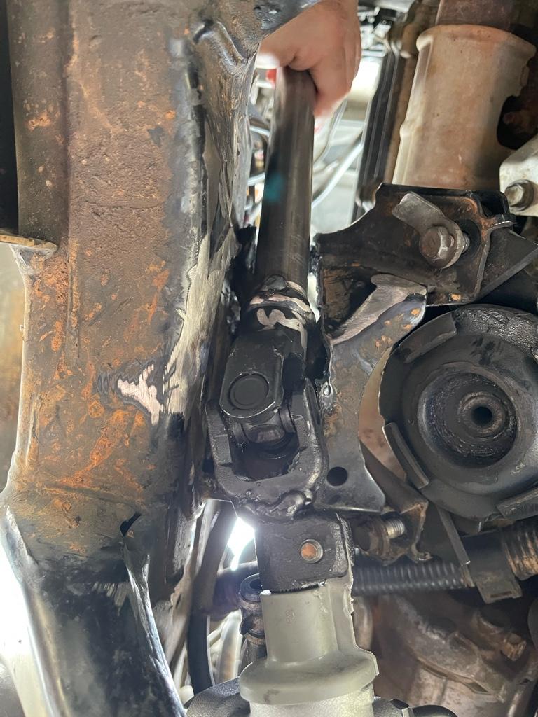
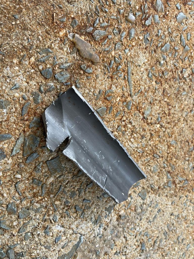
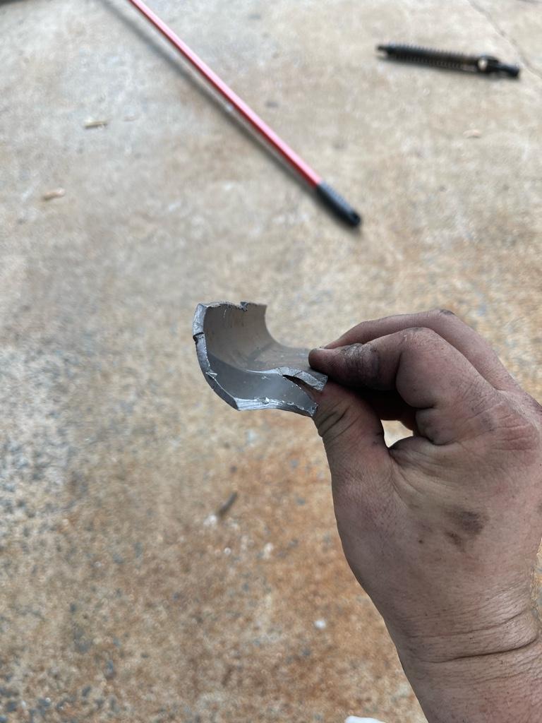
The steering shaft didn’t get done as fast as expected l.. I’ll need to get the plasma torch out to finish trimming. You can see how much I had to chunk out of it… it’s a lot.. the shortened shaft gave clearance for the u joint, but still needs to be clearanced for the shaft. Planning on cutting down a piece of large tube in half to reinforce it after while retaining clearance. I feel like I’m so close !


Sent from my iPhone using Tapatalk
 
0e22c68cf6e4a071c061b8b84eb2c10f.jpg


Preparing for paint later today. Got some rust removal gel to freshen things up a bit before I hit it with some Steelit. The wheel bearings are going to get a healthy coat of the pb blaster rust shield as well so they rust like they did last time. Took forever to get all this rust cleaned off.


Sent from my iPhone using Tapatalk
 
Prepped for paint… now if Amazon can just hurry up and deliver it already .. lol

I ended up knocking down just a bit off each high misalignment spacer to make sure I have an easy fit into the spindle with the heim. Much better now. Getting excited to get these painted and put together (hopefully my rotor still clears….. I was lazy and didn’t mount the bearing to test fit rotor after rack welding it on.. hopefully it doesn’t bite me in the ass…) so I can throw them on the car this weekend.

I feel like I’m so so close. After yesterday's steering shaft test fit I feel like I'm definitely on the right path. I'll probably end up notching a bit more material out of the MM then needed just to make sure I still have clearance after the reinforcement tube gets welded in. Really don't want to have to cut off tack weld and clearance the opening more once i get to that point.

With the MM material I'm cutting out being so thin I don't think it will take much at all to reinforce it. It really just needs to be boxed in for added strength, the upper portion of it is still in place so I'm hopeful. Just need to go see if I have any not super thick tubing laying around that will work.. if not it will be off to home depot to see if they have anything.

After cutting apart the factory steering shaft I am almost 100% convinced that the ribbed portion of the steering shaft is to protect you in the case of a severe front end impact that could possibly move the rack back, translating the force through the shaft and into the steering wheel. It is hollow inside and would collapse pretty easy. I'm getting rid of this obviously, but don't have many concerns.. with the steel bumper I have on there now the amount of impact it would take to translate all the way back to the rack would probably result in a not very survivable scenario from a g-force perspective anyway.. There isn't anything to collapse since the factory bumper and crash bar have been remove, so if the force goes anywhere it will be directly into the frame rails and then who knows lol. But just throwing that fact out there for those that may feel better about retaining the factory ribbed shaft.. I think its still very possible to use, would just require quite a bit more cutting and recessing both on the mount, and possibly on the lower frame rail.

My plan for this weekend is to first tackle the steering shaft fab so that it can cool off and be painted while I start test fitting the lower arms with the spindles but without the coilovers in place. This will let me quickly verify the suspension and rack travel to see if there are any spots of impact of binding as it turns lock to lock and fully articulates. Once that is verified i'll work on getting the front diff in, axles, coilovers, etc.

I did also notice that my drivers side JBA balljoint spindle has some messed up threads, and could be the reason I had issues getting it torqued down correctly.. so I need to swap it out for my old ball joint which ended up being perfectly fine.

The plan for the cam tab eliminator plates is to kick the front bolts all the way inboard and kick the rear ones all the way outboard. This will give me maximum clearance from the tire to the frame (also should be close to what my alignment was previously judging by some pictures I found from a few months back) and with the upper arms not being adjustable the only thing I would need to worry about getting at least partially close would be the toe which should be doable in the driveway with my aluminum angles that attach to the rotors. I'll have to get an alignment for sure, but at least this way I should be more or less close. Hopefully the rest of the alignment isn't far off spec, since flipping the plates around is a bit of a pain compared to adjusting the cams.. we'd have to pull the rig off the rack, get it up in the air, undo the 4 bolts and try a different position.. really hoping not to have to do this. Absolute worst case scenario if the alignment just doesnt work out I'm not completely against going back to the alignment cam.. but really want to stay away from it if at all possible.. Stay tuned!


4217f71814a35018ea3755d97a71112f.jpg


Sent from my iPhone using Tapatalk
 
Last edited:
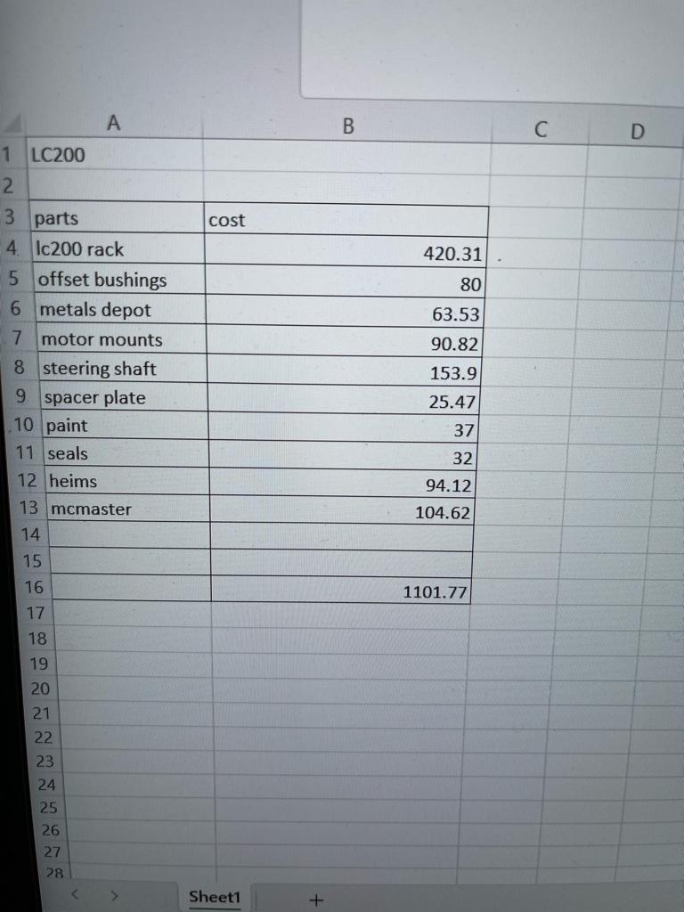
Had someone on Facebook ask me about the cost.. I said “probably 700 bucks” and then I sat down to look up receipts… how about $1,101.77? Ouch… lol

That doesn’t include the cam tabs or eliminator kit, which is another probably $200 ..
b9f25568a1c090587898c3b694927a9f.jpg


Sent from my iPhone using Tapatalk
 
Oh you big spender you! ;P


Had someone on Facebook ask me about the cost.. I said “probably 700 bucks” and then I sat down to look up receipts… how about $1,101.77? Ouch… lol

That doesn’t include the cam tabs or eliminator kit, which is another probably $200 ..
b9f25568a1c090587898c3b694927a9f.jpg


Sent from my iPhone using Tapatalk
 
Had someone on Facebook ask me about the cost.. I said “probably 700 bucks” and then I sat down to look up receipts… how about $1,101.77? Ouch… lol

That doesn’t include the cam tabs or eliminator kit, which is another probably $200 ..
b9f25568a1c090587898c3b694927a9f.jpg


Sent from my iPhone using Tapatalk
I pulled into a rest area in Alabama last year, driving my 5th gen. Some guy walking by asked how much money it cost to deck one out like I have it. I told him I had no idea, and I dont want to know.

Some things are better if I dont know.
 
Going to throw the bearings onto these in the morning and head over to try and finish the steering shaft modification.

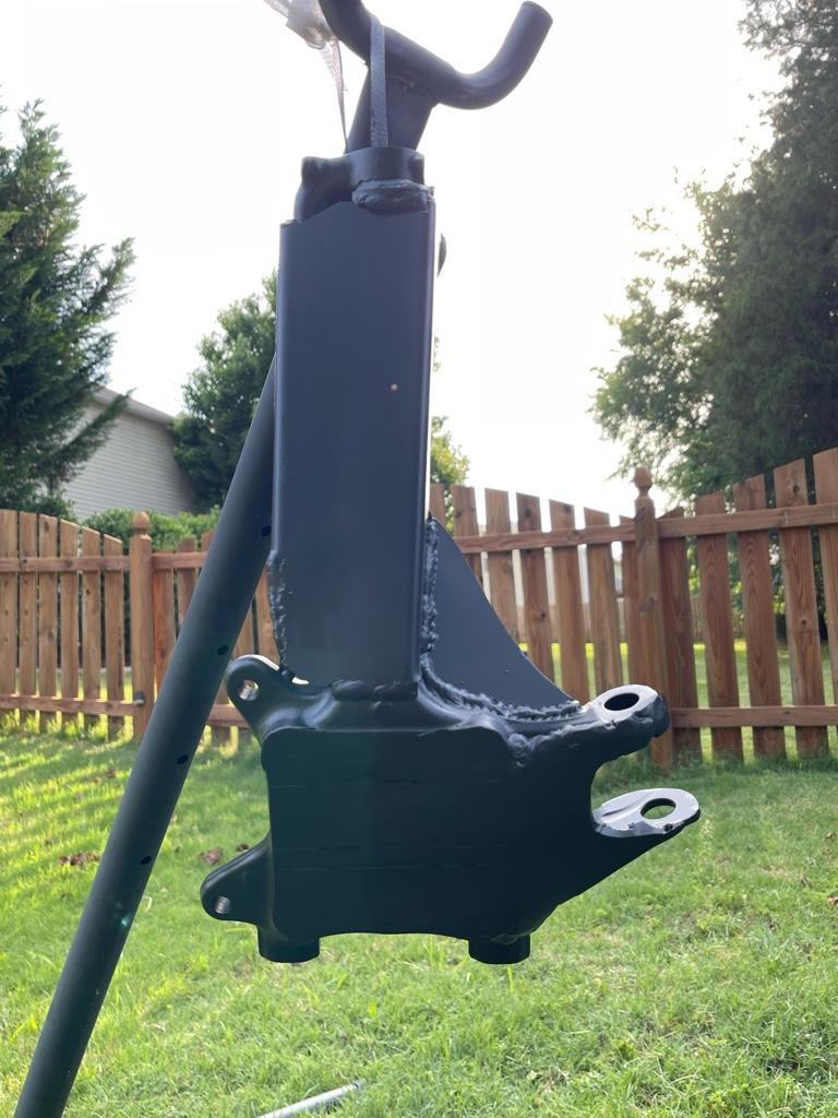
I realized today that the difference in the motor mount and steering shaft I am seeing is not an FJ cruiser vs 4runner … it’s a v6 vs a v8.. that’s why the pictures I’m seeing of the FJ are not needing to modify the MM as much of at all.. anyhow.. here is a little sneak preview of the spindles :)

9568f2f6c985f09c8022dd89c7e9732d.jpg

7ab0551f32306f81fce3f96ab8f14a09.jpg


Sent from my iPhone using Tapatalk
 
Going to throw the bearings onto these in the morning and head over to try and finish the steering shaft modification.
Loo
I realized today that the difference in the motor mount and steering shaft I am seeing is not an FJ cruiser vs 4runner … it’s a v6 vs a v8.. that’s why the pictures I’m seeing of the FJ are not needing to modify the MM as much of at all.. anyhow.. here is a little sneak preview of the spindles :)

9568f2f6c985f09c8022dd89c7e9732d.jpg

7ab0551f32306f81fce3f96ab8f14a09.jpg


Sent from my iPhone using Tapatalk
Yea, I never even considered the differences in MMs until you mentioned it. SMDH...

The Marlin instructions look like a good guide.
 
Not done .. but damn it am I close !


I’ll post up some details later, but you get the idea. The steering shaft is done , the motor mount is chopped and reinforced, and the heims are test fitted ..

Need to finish putting it all together now.. but everything as far as fab is done .. hoses are connected with some modifications.. and I think I’m on the right track.

One quick note is that I’m definitely seeing bump steer at full droop, noticeable , but not concerning. Should have plenty of toe adjustment as well. At full droop measuring where the shock drops out I think the heim bottoms out right at this point too.. maybe ever so slightly prior.. I’ll have to see once it’s all together.. I think it should be ok.. but slight chance that I may need to limit down travel by literally 1/4” or so..
c1c2ca84acdaf000dc24f37f5a7fd4b9.jpg

64148eeb73194064fe1e8d22e8c2727e.jpg

bd742c070c09d995ffd62c7ae57d2a06.jpg

a3ae8ae1ebcbe6341f3b6dfc7fbe1e2b.jpg

9eca3507f15e6940414b74d685ba6fed.jpg


Sent from my iPhone using Tapatalk
 
Alright .. now that I’ve had a couple of moments to relax here are some notes..

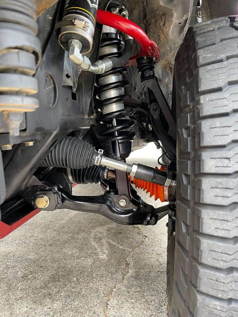
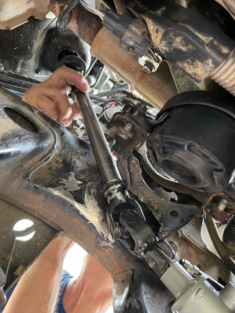
Steering shaft worked out great. Cutting down the rack side splines down and welding in the tube was perfect. The shaft I welded in was 8.25 “ long. The overall length of the shaft (after I got done and laid them next to each other ) should end up being exactly the same. I was .25” shorter overall but the splines still worked out good enough. But for anyone replicating I would suggest making it the same length just with the u joint moved down toward the rack. A plasma cutter was a must to get the MM notched.. managed to catch the welding blanket on fire so be careful.. lol

The steering shaft has a certain orientation it attaches on both ends so be mindful of where the grooves in the splines are when cutting it apart to weld in the tube. Luckily I keep my original so it was easy to match back up. I’m thinking I’m going to go ahead and modify the original shaft as well just to keep as a spare just in case..

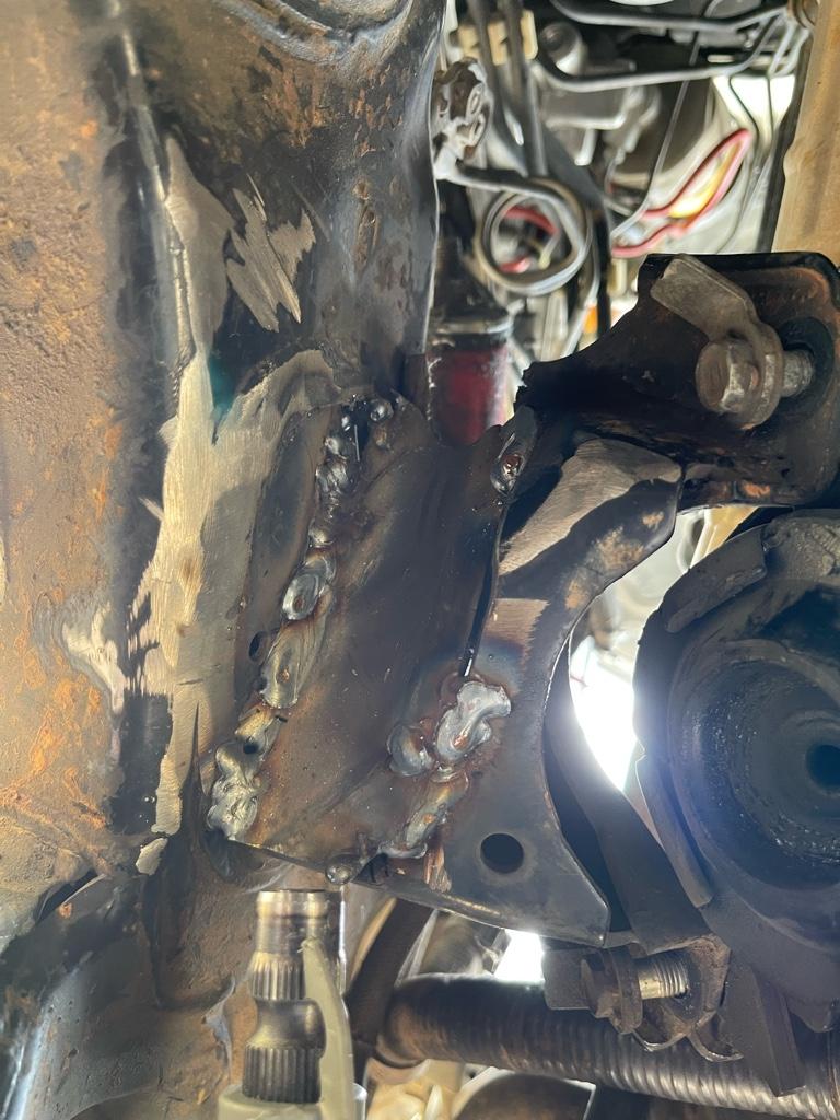
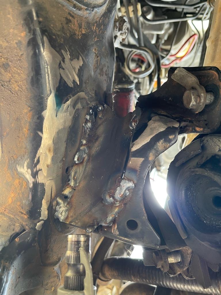
I had to cut quite a chunk of the MM out, but was able to cut a tube I had in half and beat/shape it to the opening to reinforce it, wasn’t as bad as I thought, but took quite a few tries to get it right.

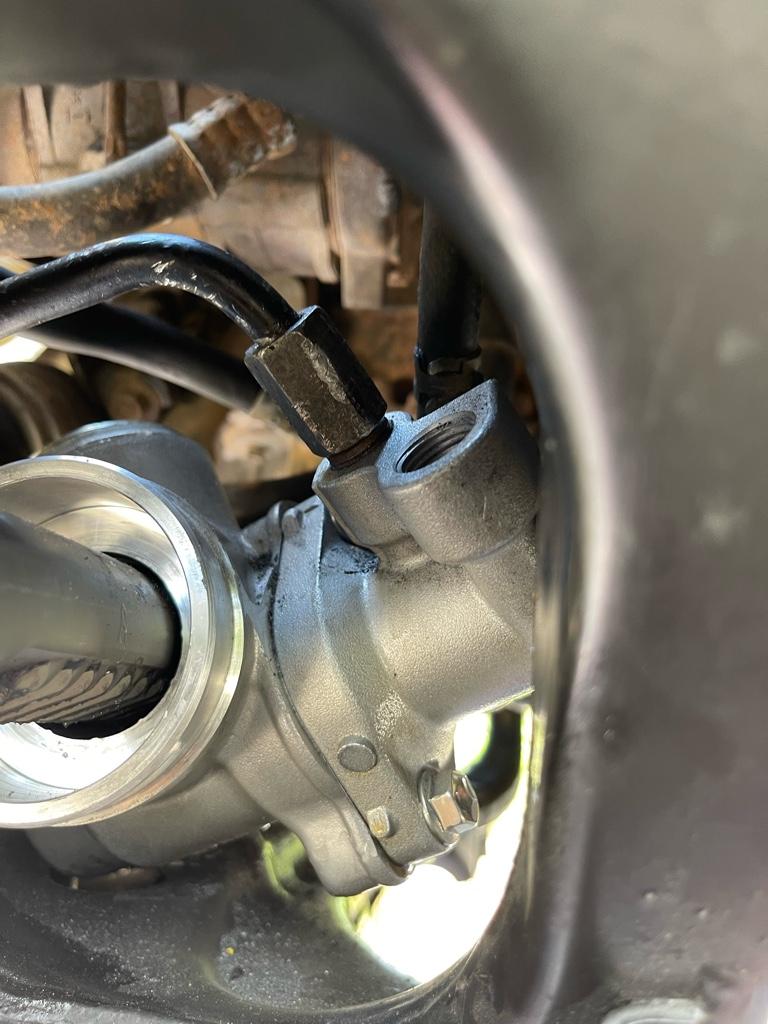
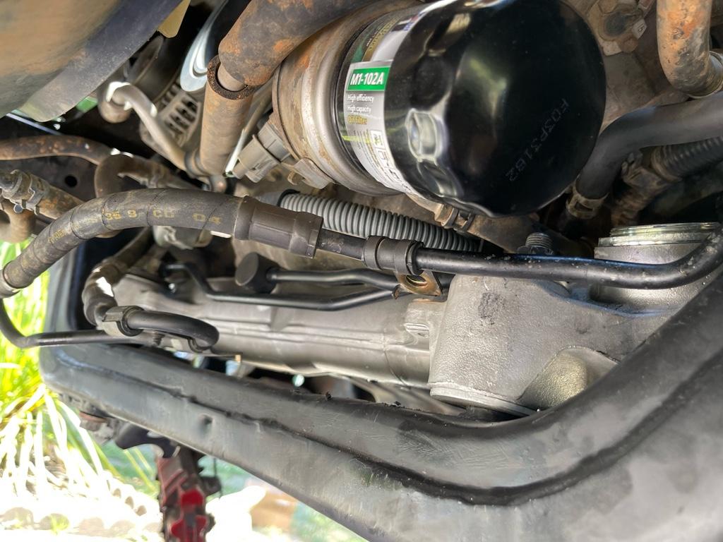
The power steering lines all bolted up and connected, but I had to bend it slightly to clear the rack to work. The other nipple coming off the the rack had to be removed to tighten down the further line , and when I reinstalled it I pointed it upwards and trimmed the oringal line to fit.

We made a small custom bracket to hold the line to the rack so it wouldn’t rub, there is a mounting point just about perfect, but the original bracket didn’t quite reach.

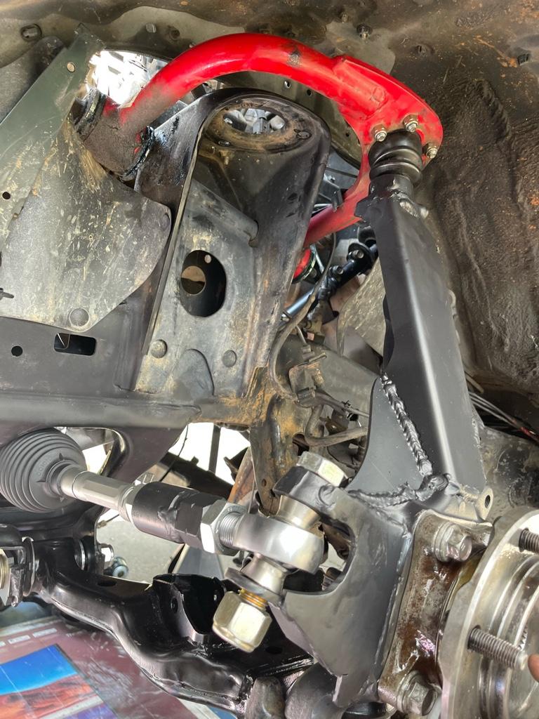
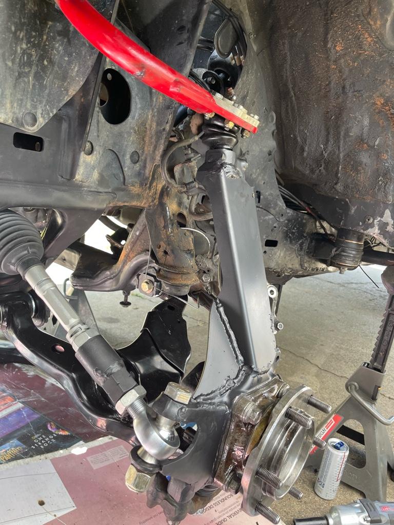
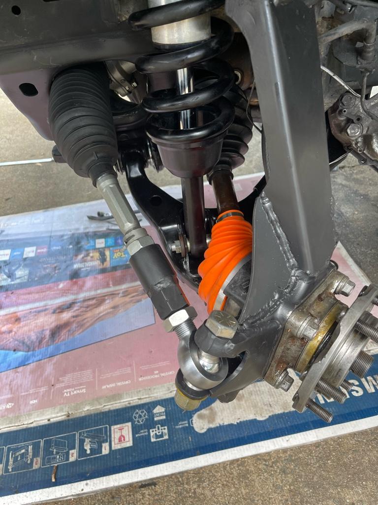
With the heim finally connected, I believe I have more than enough toe adjustment, actually ended up running the heim out a lot more than I thought I would need to. At full bump the tie rod is just above horizontal, so absolutely no issue there. At full droop the heim def bottoms out on the spacer.. luckily though, from best I can tell, this happens literally as the shock bottoms out as well so I THINK I should be ok .. the only time it would be like this is with a tire in the air so not too much force but I still want to confirm to make sure I won’t have my suspension bottoming out and hanging up on the heim itself.. not sure if that would cause any issues/damage.. but I guess we’ll see tomorrow.

Bump steer… I can tell you that cycling the suspension by hand I can see a noticeable amount of toe-in as it droops full down. Not concerned about it, but did want to mention that I can clearly see it. Doesn’t look bad at all from around ride height up to full bump, so the numbers we had discussed previously on bump steer certainly seem close.

For the coil clearance I haven’t fully verified just yet.. but eye balling where it’s supposed to sit I don’t believe I’ll have any issues at all.. should find out for sure tomorrow :)

This is a huge huge project.. definitely one of the longer mechanical projects I’ve done to the rig so far.. really hoping tomorrow will be done.. just gotta drop in the diff and put everything back together..

I already installed the drivers side control arm with the eliminator plate, we’ll see how the alignment works out soon !


Sent from my iPhone using Tapatalk

 
No plasma gun here, but I do have a half a dozen cut off disks for MM surgery. Not looking forward to it.

Long sleeves, welding gloves and a face shield will be part a major part of my week coming up.

That and lots of paint for the whole front end of the frame.

Curious how the tab eliminators work out. I have the ones from Poly Performance to put in there.

Thanks for all the pics and post op thoughts.
 
Last edited:
No plasma gun here, but I do have a half a dozen cut off disks for MM surgery. Not looking forward to it.

Long sleeves, welding gloves and a face shield will be part a major part of my week coming up.

That and lots of paint for the whole front end of the frame.

Curious how the tab eliminators work out. I have the ones from Poly Performance to put in there.

Thanks for all the pics and post op thoughts.


Take a look at my pics and cut it out once.. with the tube I used for reinforcement I have minimal clearance to the shaft.

And yes to all of the above for gear lol. Even with all the stuff I had on I managed to get sparks into my ear , my hair, burnt up my back, etc etc. it’s a messy process but it’s doable. I think if I started cutting a bigger chunk to start with a grinder would have been more than enough.

I’ll let you know once we get it on the rack for alignment.. the drivers side went together really awesome.. a little hammer action and I got them into the position I needed for both front and rear.


Really hoping my welds are sufficient lol, still in my infancy of the process, far from pretty, just hoping they are hot enough to not fail .. everything except the steering shaft is really not too concerning since it can’t fail catastrophically.. but if the shaft goes… lol


Sent from my iPhone using Tapatalk
 
Alright .. now that I’ve had a couple of moments to relax here are some notes..

Steering shaft worked out great. Cutting down the rack side splines down and welding in the tube was perfect. The shaft I welded in was 8.25 “ long. The overall length of the shaft (after I got done and laid them next to each other ) should end up being exactly the same. I was .25” shorter overall but the splines still worked out good enough. But for anyone replicating I would suggest making it the same length just with the u joint moved down toward the rack. A plasma cutter was a must to get the MM notched.. managed to catch the welding blanket on fire so be careful.. lol

The steering shaft has a certain orientation it attaches on both ends so be mindful of where the grooves in the splines are when cutting it apart to weld in the tube. Luckily I keep my original so it was easy to match back up. I’m thinking I’m going to go ahead and modify the original shaft as well just to keep as a spare just in case..

I had to cut quite a chunk of the MM out, but was able to cut a tube I had in half and beat/shape it to the opening to reinforce it, wasn’t as bad as I thought, but took quite a few tries to get it right.

The power steering lines all bolted up and connected, but I had to bend it slightly to clear the rack to work. The other nipple coming off the the rack had to be removed to tighten down the further line , and when I reinstalled it I pointed it upwards and trimmed the oringal line to fit.

We made a small custom bracket to hold the line to the rack so it wouldn’t rub, there is a mounting point just about perfect, but the original bracket didn’t quite reach.

With the heim finally connected, I believe I have more than enough toe adjustment, actually ended up running the heim out a lot more than I thought I would need to. At full bump the tie rod is just above horizontal, so absolutely no issue there. At full droop the heim def bottoms out on the spacer.. luckily though, from best I can tell, this happens literally as the shock bottoms out as well so I THINK I should be ok .. the only time it would be like this is with a tire in the air so not too much force but I still want to confirm to make sure I won’t have my suspension bottoming out and hanging up on the heim itself.. not sure if that would cause any issues/damage.. but I guess we’ll see tomorrow.

Bump steer… I can tell you that cycling the suspension by hand I can see a noticeable amount of toe-in as it droops full down. Not concerned about it, but did want to mention that I can clearly see it. Doesn’t look bad at all from around ride height up to full bump, so the numbers we had discussed previously on bump steer certainly seem close.

For the coil clearance I haven’t fully verified just yet.. but eye balling where it’s supposed to sit I don’t believe I’ll have any issues at all.. should find out for sure tomorrow :)

This is a huge huge project.. definitely one of the longer mechanical projects I’ve done to the rig so far.. really hoping tomorrow will be done.. just gotta drop in the diff and put everything back together..

I already installed the drivers side control arm with the eliminator plate, we’ll see how the alignment works out soon !


Sent from my iPhone using Tapatalk
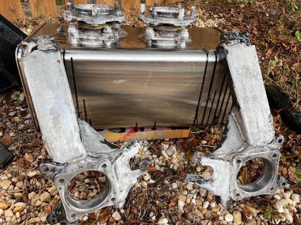
FWIW, the stock stuff does toe in a bit on droop too. from clapped OG suspension to the dobinsons 3", it toe'd in about 1.5" when measuring the front and back of the tires
 
FWIW, the stock stuff does toe in a bit on droop too. from clapped OG suspension to the dobinsons 3", it toe'd in about 1.5" when measuring the front and back of the tires


That’s certainly good input. Also.. for what it s worth I only had 1 side connected and wasn’t paying attention to the steering wheel.. so there’s a chance i was also sliding the rack left /right some


Sent from my iPhone using Tapatalk
 
Well folks.. I’m finally done after 5 hard days of work.

Will provide some feedback a little later, but the rig is together and drivable.


Sent from my iPhone using Tapatalk
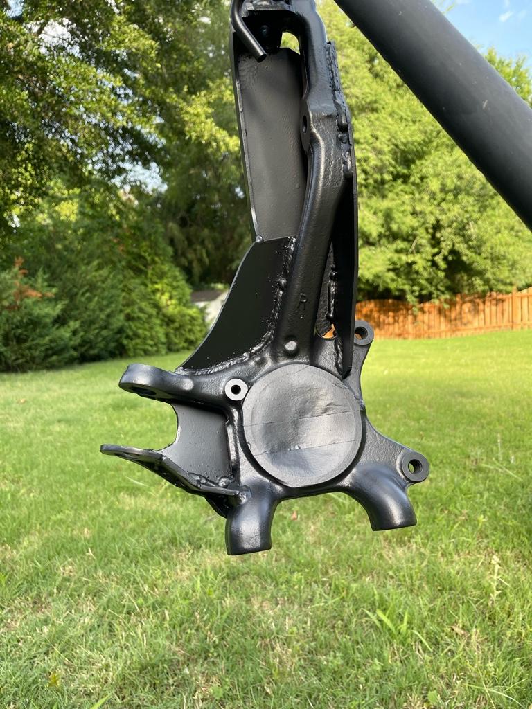
 
Not sure why the pictures are having trouble loading.

Anyhow, the rig is back together and back at home. Didn’t take too many pics for the finishing process.. was beat and hot and wanted to get it done.

One thing to note is that you need to be careful cranking down on the offset bushings.. my washer may have been very small and I guess the bushings don’t bottom out against each other inside.. so I ended crushing the top one down a bit with the impact.. lol. So I took it off and placed a really large washer in between. I feel like the rack is fairly tight , didn’t want to go too crazy. The factory diff bolt is a slightly larger diameter so it wouldn’t fit the bushing, I used the half inch hardware there.

No issues with fluid, and no issues with leaks that I see.

For the JBA ball joints.. I followed the spec of 45ft lbs of torque… I’ll keep and eye on it and see if it pops or not . Glad to have all the RCV axles back in to see how they hold up. I believe the heims bottom out right as the suspension does, I don’t see any significant rubbing on the spacers at full droop.. guess we’ll see how they hold up.

Nothing else I can think of the report from that aspect..


keeping in mind that my alignment is more than likely out of wack.. I did what I could to get the toe close as I can.. I have more than enough adjustment in and out on the tie rods I made so I’m super happy with that.

I like it .. first impressions are pretty good. There is a bit more resistance to get turning over stock.. I don’t know if this is geometry, stock pump moving a large rack.. combination, not sure, but you have to steer a bit harder which gives it the impression of a larger truck/suv, I like it.

Turning radius is good, no complaints, on road driving feels solid. Only thing I’ve noticed is that at near full lock the rack cams over, probably related to geometry, but it will not turn out straight itself, you need to make sure you steer out of a u turn. Not a big issue for me, just making a note. I’ll give a more in depth review of how it all feels when I get it aligned hopefully tomorrow.

Looking at my pics.. I’m kind of asking myself if it would be possible to mount the heim on top of the knuckle instead of under ? It would make it sit straight across an not bottom out potentially? Not that I’m changing it :)
8c01f9c5e67f39d0e9cc38bd741bd7dc.jpg

5a5cee5f1a9fbf40eea65bfd977bcc10.jpg


Sent from my iPhone using Tapatalk
 
Dropping in for a quick update after driving the rig a few more miles to drop off some samples for work.

Again, this is only on a drive-way alignment.. the toe is certainly off and is not helping, the other specs I have no idea on, but i have the front eliminator plates kicked all the way inboard, and the rears all the way outboard. I'm not sure what this is doing to my caster/toe, but I'll find out tomorrow when I can get it to my brother on the alignment rack.

One thing I can tell you is that when im parked on my sloped driver with the weight towards the rear, the front camber is really positive, looks like the shocks are offloading due to weight transfer and it makes the front end sit close to an inch or so higher than it does when I park backwards. Depending on what it looks like tomorrow on the rack I have considered adjusting the front coilovers down just a little which will impact ride height, but still retain overall travel. We'll see.

I am also working on cleaning up my original cam adjustment bolts, if for some reason we can't make the eliminator plates work I'm not against going back to the cams since I now have gussets, and I'll just throw a paint line across them and if they move I'll have a quick visual and the adjustment is super easy. Hoping not to have to, but the option certainly is there.


Anyway, onto the driving. Still not sure exactly what is causing it, and it really isn't an issue at all to me, but at about 3/4 turns prior to full lock you can feel the steering wheel/wheels fall over towards full lock. Just driving forward you won't come out of this and have to steer out. I felt it start doing this back out of the driveway this morning, and definitely while making a U-turn. Nothing bad for me, just found it interesting. I am suspecting something to do with the heim joint as the angle progresses and the tie-rod falls behind the axis, I'll do some more looking and see if I can figure it out .


As far as driving down the road, the steering wheel feel is great. I like it. Again, from a 12 oclock position as you start steering, there is more resistance to the wheel, but it feels appropriate to the overall rig, beefy. As you continue turning it feels very solid, and until you get to the over-camming near full lock feels very consistent. Right now the steering wheel doesn't return back to center as easy, but this could very well be an issue of alignment still. More to report on this later.

I THINK I am feeling the bump steer a little, but I'm not sure, since I don't know what it's supposed to feel like lol. I can say with confidence that there is definitely a change to the feel/reaction of the rig as you go over uneven bumps/road surfaces, particularly at highway speeds (not very noticeable at all under 50-60mph) when one wheel loads/offloads different from another. Going over something like rail road tracks head-on there is not issue, but I definitely feel something funky when you're in a turn and one side dips or bumps up, feels like the steering wheel unloads a bit, which could be because one of the wheels is starting to bump steer either in or out? At first I felt a bit un-easy, but on the way back home as I got more seat-time with it I felt great. I'm thinking my initial impression was skewed just by the different feel maybe, not sure yet.


I know it's not a great review/feedback yet, but I just wanted to say that I drove it 30 miles, mainly at highway speeds with bumps and turns and road work, and by the time I got home I felt like I wasn't even paying attention to what the steeringwheel was doing or what I had to do with it.. Hoping to really give some good feedback once we get the alignment sorted because it's obviously not very good feedback to give on a new rack when my alignment could be all sorts of out of whack. Keep in mind I also have brand new lower arms with much stiffer bushings than stock that could also be translating a lot more feel than I was feeling prior.. anyhow, at least it isn't a complete failure out of the box yet and looking promising!
 
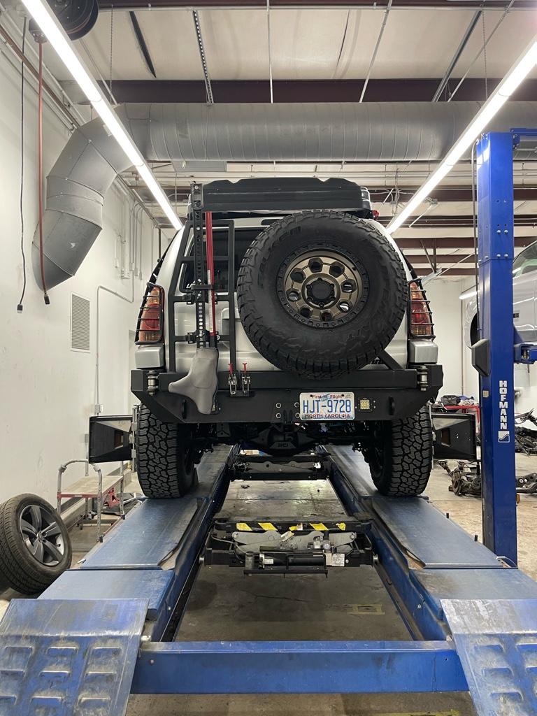
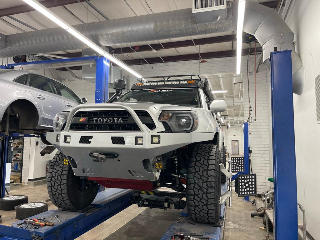
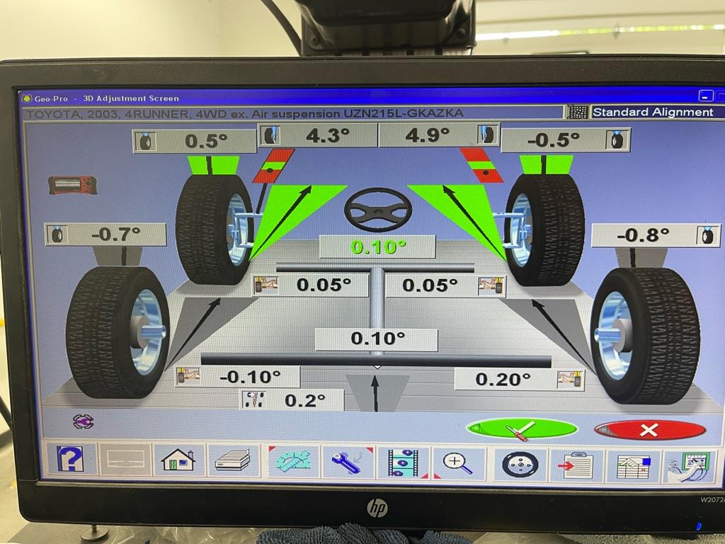
Well, the alignment is pretty damn good now. Only thing out was the toe, really bad, so I’m about to see how it drives on the way home. Caster worked out great. Camber is a bit funky with one side positive other negative but tires are parallel.

If it still drives funky from here on out it’s the new rack geometry… soooo wish me luck lol.

839cca3554058b4b77d881031820e2d9.jpg

4c0d448f49bf8682833b60a7a3911731.jpg

0610d8a9fb5cd28df4e9ab87b4f5f39b.jpg


Sent from my iPhone using Tapatalk
 

Members online

Forum statistics

Threads
278,311
Messages
3,554,082
Members
248,016
Latest member
Advally Service

Trending content

Back
Top