Another Map Lights with Dome Lights 2002 Model

Speedy

Member
I've been reading up interior lighting ideas and found a few threads about people wanting to get the map lights to work with the door switches or dome light in 2000 and up 4Runners that have the newer map light.

[MENTION=446904]R3Z3N[/MENTION] posted this diagram, but I'm not sure it's correct. I disassembled my map light and did some testing with a power probe and multi meter and the lights are constantly grounded AND constantly powered with +12V. The +12V goes through the little switches which are SPDT so when you flip the switch voltage (current) flows through the switch, through the bulb, to ground in the bulb's housing. I think the wiring diagram in the EWD is backward for the map light.

4Runner%20Interior%20LED%20wiring.gif


I think the switch should be on the other side of the map light bulbs in this diagram.

t1zim40l.jpg


[MENTION=116195]weekendclimber[/MENTION] posted up some good info, hoping he has input.

[MENTION=10169]TheDurk[/MENTION] also seems to be good with these wiring issues as well.

I do not want to replace my map light with a 2nd gen unit and I figure there has to be a way to get this to work.

The wiring in the actual light has a grey wire going to the common pin on the 3 pin switch (middle pin). This grey wire corresponds to blue with yellow stripe in the connector which we know is the dome light +12V source. A yellow wire comes off pin 1 and goes to the positive side of the bulb socket. The bulb then grounds on the socket itself and the housing is grounded via a black wire with red dots that goes to the 8 pin connector (mine has a sunroof non may be different).

The only way I can think to get the map lights to activate with the doors, is to somehow get +12V to the yellow wire that lights the bulbs but since the doors are ground switched I can't sort it out. There is a light green with black stripe wire that I "think" is ground for the entire system. It goes to the dome and the combination meter.

Anyone ever figure this out? Maybe a relay that is ground switched with constant +12V on one pin and the output to the map light bulbs +12v yellow wire?
 
Last edited:
Register to hide this ad
I can dig in on this if [MENTION=10169]TheDurk[/MENTION] doesn't beat me to it :-) I'm sure someone has probably figured this out. If not, I think the best way would be a relay off of the front dome that switches ground before the map light switches. Kind of ugly, but would work.

Just so I'm super clear what you're looking for, you want the map lights (M3) to also turn on when the doors open, depending on whether the switch in the dome light (I18) is set to "Door". Let me know if that's not clear.

ONe thing I'd like to just go out and say is that it's sad that I have a FSM on my work computer desktop. There I said it!
 
^Correct, the switches just close the circuit. However the wiring is not actually tied into the door switches, I just did not want to draw in the logic for how the lights come on with the doors open.

The main point, being for my diagram, tie in to the ground side of the light, but before the switch with a diode such that the lights will turn on individually and with the door, which in this case, you can just ground the new wiring.
 
I'd like the map lights to come on when any of the passenger doors open (not the rear hatch) but still be able to turn the map lights on/off with the switch when the doors are all closed. Bonus points if this turns off when the dome light switch is in the "OFF" position. I do not want the map lights to come on when the dome is in the "ON" position.

I have the FSM on my work computer too LOL. Been staring at this diagram for 2 days and have the map light sitting on my desk as well haha.

Grabbing the LG-B wire I think is the ground that would tie to all the door switches since that appears to activate the dome light when the switch is on the "DOOR" setting. However with the map light bulbs already being grounded all the time, that won't work.

I had hoped there may be a way to use the 3rd pin on the SPDT switch that activates the map lights. That pin is unused in the factory configuration.
 
^Correct, the switches just close the circuit. However the wiring is not actually tied into the door switches, I just did not want to draw in the logic for how the lights come on with the doors open.

The main point, being for my diagram, tie in to the ground side of the light, but before the switch with a diode such that the lights will turn on individually and with the door, which in this case, you can just ground the new wiring.

I must be missing something simple. You can't tie in to the ground side of the light, it's an aluminum housing that's grounded. You could tap a strap to it I guess, but then you just have a ground wire. I'm missing how the lights get +12V when the door opens I think?

Like I said I think the FSM EWD is incorrect above, at least physically how it's wired. Logically it's right but the switch should be on the +12V side not the GND side. I'll try to get a photo posted tonight of what it looks like.
 
Last edited:
Like this:

LrFl4sk.png


[MENTION=446904]R3Z3N[/MENTION], I can't seem to think about if this would need a diode or not.

edit: I see what you're saying about the diode. It would go between the lights.
 
Last edited:
I'd like the map lights to come on when any of the passenger doors open (not the rear hatch) but still be able to turn the map lights on/off with the switch when the doors are all closed. Bonus points if this turns off when the dome light switch is in the "OFF" position. I do not want the map lights to come on when the dome is in the "ON" position.

I have the FSM on my work computer too LOL. Been staring at this diagram for 2 days and have the map light sitting on my desk as well haha.

Grabbing the LG-B wire I think is the ground that would tie to all the door switches since that appears to activate the dome light when the switch is on the "DOOR" setting. However with the map light bulbs already being grounded all the time, that won't work.

I had hoped there may be a way to use the 3rd pin on the SPDT switch that activates the map lights. That pin is unused in the factory configuration.
Too bad the map light switches are on the 12V side of the bulbs. I believe the non-sunroof model is as shown (the ground for the lights is also one of the mounting screws too). I'd have to check on my unit to verify though...

Your request for the ideal light operation is a bit of having your cake and eating it too... You will either get:

- Map lights always turning on with the doors (no matter dome switch position) and never with dome in "ON" position
or
- Map lights always turning on when the dome light is on (whether in door or on positions)

Unless you play some extra trickery with multiple relays, etc.

Swapping 'polarity' of the dome light signal to control the map lights is a simple single relay circuit at least...

-Charlie
 
A relay was where my mind was headed like [MENTION=116195]weekendclimber[/MENTION] posted above. I'm trying to find a simple online electronic simulator to see how that would work.
 
A relay was where my mind was headed like [MENTION=116195]weekendclimber[/MENTION] posted above. I'm trying to find a simple online electronic simulator to see how that would work.
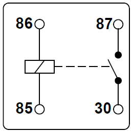
Relays are simple.

Make_and_break_relay.png


If there is 12V across 86/85 (polarity doesn't matter), 87 and 30 connect.

weekendclimber's diagram is wrong though - assuming the map light switches are on the 12V side of the bulbs. The relay will never turn on also (the LG-B wire is ground or open circuit, never 12V).

Connect:
85: LG-B (map on with doors no matter what)
*or*
85: Pole of SP3T switch in dome light (map on with dome no matter what)
86: 12V constant (L-Y wire at map light or dome light)
87: 12V constant
30: Map light bulbs through diodes to keep map light switch operation separate

Hopefully that makes sense...

-Charlie
 
In my GIF, the Diodes for the Map lights are there so that you have independent control of them.

To try it out go here:
Circuit Simulator

and Import from Text, then paste this in to see why the diodes are needed...

Code:
$ 1 0.0000049999999999999996 10.20027730826997 50 12 43
R -528 -128 -528 -176 0 0 40 12 0 0 0.5
w -528 -48 -528 32 0
162 -528 32 -528 96 2 default-led 1 1 1 0.1
s -528 96 -528 160 0 1 false
w -528 32 -400 32 0
s -400 96 -400 160 0 1 false
162 -400 32 -400 96 2 default-led 1 1 1 5
w -528 -48 -272 -48 0
w -272 -48 -272 32 0
162 -272 32 -272 96 2 default-led 1 1 1 0.1
w -288 160 -288 240 0
S -272 96 -272 160 0 1 false 0 2
g -256 160 -256 176 0
s -288 272 -288 336 0 1 false
g -288 336 -288 352 0
g -400 160 -400 176 0
g -528 160 -528 176 0
w -528 96 -560 96 0
w -400 96 -432 96 0
w -432 240 -288 240 0
w -432 240 -560 240 0
d -432 96 -432 240 2 default
w -528 -128 -528 -80 0
w -528 -80 -528 -48 0
w -528 -80 -80 -80 0
g -64 160 -64 176 0
S -80 96 -80 160 0 1 false 0 2
w -96 160 -96 240 0
162 -80 32 -80 96 2 default-led 1 1 1 0.1
w -80 -80 -80 32 0
w 48 -80 48 32 0
162 48 32 48 96 2 default-led 1 1 1 0.1
w 32 160 32 240 0
S 48 96 48 160 0 1 false 0 2
g 64 160 64 176 0
w -80 -80 48 -80 0
w 48 -80 176 -80 0
g 192 160 192 176 0
S 176 96 176 160 0 1 false 0 2
w 160 160 160 240 0
162 176 32 176 96 2 default-led 1 1 1 0.1
w 176 -80 176 32 0
w -96 240 32 240 0
w 32 240 160 240 0
g 32 336 32 352 0
s 32 272 32 336 0 1 false
x -512 67 -482 70 4 12 MapL
x -250 67 -187 70 4 12 Front\sDome
x -382 69 -350 72 4 12 MapR
x -62 68 9 71 4 12 Center\sDome
x 65 70 131 73 4 12 Hatch\sDome
x 197 70 228 73 4 12 Hatch
x 53 310 152 313 4 12 Hatch\sDoor\sSwitch
x -271 300 -165 303 4 12 Main\sDoor\sSwitches
w -288 240 -288 272 0
w 32 240 32 272 0
x -59 141 -43 144 4 12 On
x 67 143 83 146 4 12 On
x 196 141 212 144 4 12 On
x -250 140 -234 143 4 12 On
x -550 145 -534 148 4 12 On
x -424 145 -408 148 4 12 On
d -560 96 -560 240 2 default
x -649 302 -507 305 6 12 1N4001\sor\s1N5406\sDiodes
x -648 278 -326 281 4 12 Wiring\sfrom\sMap\sto\sFront\sdome\sis\sBEFORE\sMap\slight\sswitch!
w -656 272 -656 80 0
w -656 80 -560 80 0
 
Last edited:
Thanks that's actually the sim I was playing with today with the relay so good to know at least I was in a familiar spot LOL. I think yours will work great for switches on the ground side.

[MENTION=139000]phattyduck[/MENTION] - when you say "85: Pole of SP3T switch in dome light (map on with dome no matter what)" does that mean the other pole that's unused on the SPDT switch? I confirmed tonight the other side definitely gets +12V when the map light is switched "off".
 
Last edited:
[MENTION=139000]phattyduck[/MENTION] - when you say "85: Pole of SP3T switch in dome light (map on with dome no matter what)" does that mean the other pole that's unused on the SPDT switch? I confirmed tonight the other side definitely gets +12V when the map light is switched "off".
I was thinking of connecting it to the pin of the switch that goes to the light. If you connect it to the unused pin, you can omit the diodes, so that is probably better/easier.

-Charlie
 
weekendclimber's diagram is wrong though - assuming the map light switches are on the 12V side of the bulbs. The relay will never turn on also (the LG-B wire is ground or open circuit, never 12V).

Connect:
85: LG-B (map on with doors no matter what)
*or*
85: Pole of SP3T switch in dome light (map on with dome no matter what)
86: 12V constant (L-Y wire at map light or dome light)
87: 12V constant
30: Map light bulbs through diodes to keep map light switch operation separate

Hopefully that makes sense...

-Charlie

Here's a diagram with [MENTION=139000]phattyduck[/MENTION]'s wiring and I agree this is much better. I was assuming that the LG-B would be getting 12v when the dome comes on and I trust his knowledge on whether it is or not. I'm still failing to see why a diode would be necessary on the map lights (M3) though, as we're only grounding them.

One thing to note, both map lights would come on when using the factory on-off switch in this diagram. If you used two relays wired the same, but for pin 30 going to only one of the map light (M3), this would fix that issue.

BxNEyA2.png
 
Here's a diagram with [MENTION=139000]phattyduck[/MENTION]'s wiring and I agree this is much better. I was assuming that the LG-B would be getting 12v when the dome comes on and I trust his knowledge on whether it is or not. I'm still failing to see why a diode would be necessary on the map lights (M3) though, as we're only grounding them.

One thing to note, both map lights would come on when using the factory on-off switch in this diagram. If you used two relays wired the same, but for pin 30 going to only one of the map light (M3), this would fix that issue.

BxNEyA2.png
This is getting close. Couple of things:

- The LB-B wire gets grounded when the doors are open (thus the other side of the relay coil is connected to constant power)
- You can also optionally connect the trigger for the relay to the wire between the dome light bulb and the switch so the map lights turn on whenever the dome light is on.
- You can use diodes instead of a second relay at the map lights to keep the switch operation separate with the OEM map light switches
- The diagram for the map lights is 'upside down' for the sunroof models - so it would be better to draw the connection for the 87 pin to the other side of the switch instead of its own ground.
- The direction you have to place the diodes will depend on the direction of current flow to the map light switches (cathode (marked line) always goes to the lower voltage side). So, towards ground on the non-sunroof models and towards the bulb on the sunroof models.

Yeah, its hard to explain in words, sorry!

-Charlie
 
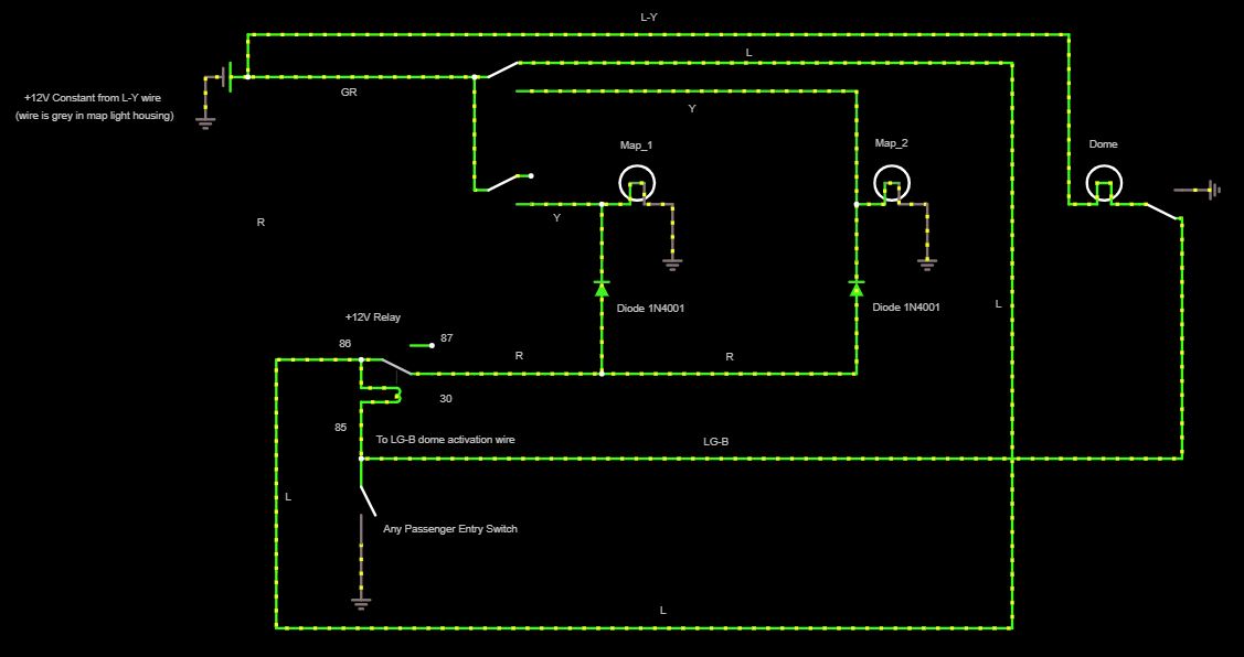
This has been a big help and got me pointed in the right direction. I knew a relay would get it done, but just wasn't quite sure the proper orientation. I've run what I think is the best config in the simulator and it works. With a diode on the +12V going from the relay to the map lights you can keep the map lights working independent from each other.

I'm now on the hunt for a "micro" relay that's tiny and will fit up in the map light console easily. Found this one that I think will do the trick. I was hoping there'd be a pigtail to go with it, but looks like it's solder straight to the pins.

Internal Error

I'm obviously going to test the LG-B wire to insure it is grounded when the doors open, but I'm pretty sure it does.

Sharp folks on this forum.
 
This has been a big help and got me pointed in the right direction. I knew a relay would get it done, but just wasn't quite sure the proper orientation. I've run what I think is the best config in the simulator and it works. With a diode on the +12V going from the relay to the map lights you can keep the map lights working independent from each other.

I'm now on the hunt for a "micro" relay that's tiny and will fit up in the map light console easily. Found this one that I think will do the trick. I was hoping there'd be a pigtail to go with it, but looks like it's solder straight to the pins.

Internal Error

I'm obviously going to test the LG-B wire to insure it is grounded when the doors open, but I'm pretty sure it does.

Sharp folks on this forum.

Is there a way to share your simulator? I'd love to see it just for learning purposes :-)

Cheers [MENTION=8729]Speedy[/MENTION]
 
Ok small wrinkle (maybe). I wanted a full simulation so I added the dome light to the sim. Everything seemed to work perfect, however when I de-activate the door switch in the sim, the lights continue to illuminate for a few and it looks like current is trying to flow backward through the relay. Eventually the relay turns off and the lights go out. I'm not sure that's even possible never had a situation like this before.

I'm not sure what happens with the LG-B wire when it goes through the combination meter (presumably it goes to ground when one of the doors open) but I'm not sure if there's other circuitry in there preventing backward current flow. Having the dome light ground there as well as the relay seems to be giving the sim some kind of issue. I've tried diodes in various places to see if that solves it, but so far no dice.

A diode may be required at the dome light, but I'd only want to do that as a last resort. I'm trying not to mess with the factory wires anymore than absolutely necessary.
[MENTION=139000]phattyduck[/MENTION] [MENTION=116195]weekendclimber[/MENTION]

4runner_map_circ.jpg
 
Last edited:
Ok small wrinkle (maybe). I wanted a full simulation so I added the dome light to the sim. Everything seemed to work perfect, however when I de-activate the door switch in the sim, the lights continue to illuminate for a few and it looks like current is trying to flow backward through the relay. Eventually the relay turns off and the lights go out. I'm not sure that's even possible never had a situation like this before.

I'm not sure what happens with the LG-B wire when it goes through the combination meter (presumably it goes to ground when one of the doors open) but I'm not sure if there's other circuitry in there preventing backward current flow. Having the dome light ground there as well as the relay seems to be giving the sim some kind of issue. I've tried diodes in various places to see if that solves it, but so far no dice.

A diode may be required at the dome light, but I'd only want to do that as a last resort. I'm trying not to mess with the factory wires anymore than absolutely necessary.
If you are seeing that operation at the relay, it means the sim is doing its job. The relay coil is also an inductor, and will continue to try to pull current through the coil when door entry signal switch is opened. Most automotive relays have a diode or resistor snubber in them to reduce this effect. You can also do it externally with a diode or resistor. The dome light bulb will also do it if it is an incandescent. This is not an effect you will see in real life though (just something you have to be aware of to keep sensitive circuitry safe in some/many cases).

The power for the relay now will act a bit odd - when the map 2 switch is turned on, it will turn off the map 1 light if the dome light is on. And in this configuration, you will need diodes.

I had made the (incorrect) assumption that the map light switches had the pole towards the lights and the NO and NC connections towards the power. From your earlier descriptions, I should have been able to figure it out.

If the map light switches are 'reversed' (power in and out connections reversed) and the power for the relay is moved to 'constant', then you can connect the output to the unused (NC) map light switch connections and you won't need the diodes.

-Charlie
 
Ok small wrinkle (maybe). I wanted a full simulation so I added the dome light to the sim. Everything seemed to work perfect, however when I de-activate the door switch in the sim, the lights continue to illuminate for a few and it looks like current is trying to flow backward through the relay. Eventually the relay turns off and the lights go out. I'm not sure that's even possible never had a situation like this before.

I'm not sure what happens with the LG-B wire when it goes through the combination meter (presumably it goes to ground when one of the doors open) but I'm not sure if there's other circuitry in there preventing backward current flow. Having the dome light ground there as well as the relay seems to be giving the sim some kind of issue. I've tried diodes in various places to see if that solves it, but so far no dice.

A diode may be required at the dome light, but I'd only want to do that as a last resort. I'm trying not to mess with the factory wires anymore than absolutely necessary.
[MENTION=139000]phattyduck[/MENTION] [MENTION=116195]weekendclimber[/MENTION]

Let me look through your diagram a little more if [MENTION=139000]phattyduck[/MENTION] doesn't beat me to it. This is what I came up with flipping the map lights around (M3):

t4Uv2bI.png
 

Members online

Forum statistics

Threads
278,307
Messages
3,554,050
Members
248,016
Latest member
Advally Service

Trending content

Back
Top