

dsfra
Member
Instead of writing it over again, I'll just paste in what I sent to AOB:
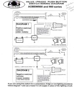
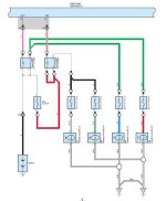
I ordered 3 switches for my Toyota "4Runner 2010-ON" from you, and am connecting one of them to my LED light bar, with the relay to be triggered by the highbeams. The wiring diagram that came with the switches is titled "HILUX / PRADO PUSH BUTTON SWITCH WIRING DIAGRAM". Please confirm that this diagram is applicable to my 2012 4Runner Trail. Beyond that, I am not sure whether I should be using "DIAGRAM 1 Positive switched vehicles (older models) or "DIAGRAM 2 Negative switched vehicles (newer models) 1 amp diode required". Is a 2012 4Runner considered an "older model" (Diagram 1) or a "newer model" (Diagram 2)? Looking at the factory 2010 wiring diagram (which applies to 2012 vehicles as well), it appears that the + 12 v. comes out of the "Main Body ECU" and triggers the factory highbeam relay, then we have a 10 A. fuse, then the highbeam bulb, then go to chassis ground - with no switching on the ground side of the highbeam bulb. This would suggest that I should be using DIAGRAM 1, since according to the factory wiring diagram it sure looks like the highbeams are not negative switched. Can you please confirm this?
What I got back:
Sorry i am not an auto electrician but going by your info i would say it is positive switched so use diagram 1. If you are still unsure maybe see what you can find online.
I appreciate AOB's response, but it doesn't answer the question, and I am really inclined to tread carefully here since - per a couple of recently active threads - it's all too easy to screw up and fry a few hundred dollars worth of ECU's. I know there was a recent group buy for AOB switches, and I assume that some of you guys received the same wiring diagram from AOB and have installed your switches on 2012's. So the question is: Which did you use - Diagram 1 or Diagram 2?
I have already spent way over an hour searching and have looked at a couple hundred posts, but apparently my little pea-brain just can't quite figure this one out. It looks to me like I should use Diagram 1 and tap my LED light bar relay trigger from the Green / Black Stripe wire on my left highbeam. Is that what you guys did? Anyone? I already have a handful of 1N4001's sitting around, and really don't care which way it goes - I just want to get it wired and done with.
EDIT: My VOM sez that the White / Black Stripe wire goes to ground when the highbeams are both on and off, and the Green / Black Stripe wire is + 12 v. exactly when the highbeams are on. This would suggest that Diagram 1 is in effect. Then why did AoB send the 2 wiring diagrams and say that Diagram 2 should be used for "newer models"? Does AoB consider the 2010-13 4Runners to be "Diagram 1 - older models" and the 2014-15's to be "Diagram 2 - newer models"? No one seems to know. Still don't even know whether their diagrams apply to 4Runners or not - or just Hilux / Prado. Why is this so damn difficult?
I ordered 3 switches for my Toyota "4Runner 2010-ON" from you, and am connecting one of them to my LED light bar, with the relay to be triggered by the highbeams. The wiring diagram that came with the switches is titled "HILUX / PRADO PUSH BUTTON SWITCH WIRING DIAGRAM". Please confirm that this diagram is applicable to my 2012 4Runner Trail. Beyond that, I am not sure whether I should be using "DIAGRAM 1 Positive switched vehicles (older models) or "DIAGRAM 2 Negative switched vehicles (newer models) 1 amp diode required". Is a 2012 4Runner considered an "older model" (Diagram 1) or a "newer model" (Diagram 2)? Looking at the factory 2010 wiring diagram (which applies to 2012 vehicles as well), it appears that the + 12 v. comes out of the "Main Body ECU" and triggers the factory highbeam relay, then we have a 10 A. fuse, then the highbeam bulb, then go to chassis ground - with no switching on the ground side of the highbeam bulb. This would suggest that I should be using DIAGRAM 1, since according to the factory wiring diagram it sure looks like the highbeams are not negative switched. Can you please confirm this?
What I got back:
Sorry i am not an auto electrician but going by your info i would say it is positive switched so use diagram 1. If you are still unsure maybe see what you can find online.
I appreciate AOB's response, but it doesn't answer the question, and I am really inclined to tread carefully here since - per a couple of recently active threads - it's all too easy to screw up and fry a few hundred dollars worth of ECU's. I know there was a recent group buy for AOB switches, and I assume that some of you guys received the same wiring diagram from AOB and have installed your switches on 2012's. So the question is: Which did you use - Diagram 1 or Diagram 2?
I have already spent way over an hour searching and have looked at a couple hundred posts, but apparently my little pea-brain just can't quite figure this one out. It looks to me like I should use Diagram 1 and tap my LED light bar relay trigger from the Green / Black Stripe wire on my left highbeam. Is that what you guys did? Anyone? I already have a handful of 1N4001's sitting around, and really don't care which way it goes - I just want to get it wired and done with.
EDIT: My VOM sez that the White / Black Stripe wire goes to ground when the highbeams are both on and off, and the Green / Black Stripe wire is + 12 v. exactly when the highbeams are on. This would suggest that Diagram 1 is in effect. Then why did AoB send the 2 wiring diagrams and say that Diagram 2 should be used for "newer models"? Does AoB consider the 2010-13 4Runners to be "Diagram 1 - older models" and the 2014-15's to be "Diagram 2 - newer models"? No one seems to know. Still don't even know whether their diagrams apply to 4Runners or not - or just Hilux / Prado. Why is this so damn difficult?
Attachments
Last edited:


